 Open Access Article
Creative Commons Attribution 3.0 Unported Licence
The cluster beam route to model catalysts and beyond
Peter R.
Ellis
a,
Christopher M.
Brown
a,
Peter T.
Bishop
a,
Jinlong
Yin
b,
Kevin
Cooke
b,
William D.
Terry
c,
Jian
Liu
c,
Feng
Yin
c and
Richard E.
Palmer
*c
aJohnson Matthey Technology Centre, Blount's Court, Sonning Common, Reading RG4 9NH, UK. E-mail: r.e.palmer@bham.ac.uk
bTeer Coatings Ltd., Miba Coating Group, West Stone House, West Stone, Berry Hill Industrial Estate, Droitwich, Worcestershire WR9 9AS, UK
cNanoscale Physics Research Laboratory, School of Physics and Astronomy, University of Birmingham, Birmingham B15 2TT, UK
First published on 20th January 2016
Abstract
The generation of beams of atomic clusters in the gas phase and their subsequent deposition (in vacuum) onto suitable catalyst supports, possibly after an intermediate mass filtering step, represents a new and attractive approach for the preparation of model catalyst particles. Compared with the colloidal route to the production of pre-formed catalytic nanoparticles, the nanocluster beam approach offers several advantages: the clusters produced in the beam have no ligands, their size can be selected to arbitrarily high precision by the mass filter, and metal particles containing challenging combinations of metals can be readily produced. However, until now the cluster approach has been held back by the extremely low rates of metal particle production, of the order of 1 microgram per hour. This is more than sufficient for surface science studies but several orders of magnitude below what is desirable even for research-level reaction studies under realistic conditions. In this paper we describe solutions to this scaling problem, specifically, the development of two new generations of cluster beam sources, which suggest that cluster beam yields of grams per hour may ultimately be feasible. Moreover, we illustrate the effectiveness of model catalysts prepared by cluster beam deposition onto agitated powders in the selective hydrogenation of 1-pentyne (a gas phase reaction) and 3-hexyn-1-ol (a liquid phase reaction). Our results for elemental Pd and binary PdSn and PdTi cluster catalysts demonstrate favourable combinations of yield and selectivity compared with reference materials synthesised by conventional methods.
1 Introduction
Catalysis has always been “nanotechnology”, in the sense that catalyst particles have nanometre dimensions, but the increased level of material control which nanotechnology now offers is an obvious attraction for those who seek to understand and improve the function of catalysts. Even within the bounds of nanotechnology, there are many ways to create “designer” catalyst particles, including the adoption of micro/nanolithographic approaches1 and colloidal routes.2 A relatively new player in this scene is the cluster beam route to model catalyst production,3 in which atomic clusters (i.e. nanoparticles) are generated in the gas phase (typically) and deposited onto the catalyst support as a beam in high vacuum, sometimes with a mass-selection step prior to the deposition stage. Both heterogeneous and electro/photo-catalysis are the subjects of active current research.The potential advantages of the cluster beam approach are several: (i) the size of the catalyst particle can be selected even to single atom precision;4 (ii) the (direct) interaction between the metal cluster and the support can sometimes be tuned by the energy of the impacting particle;5 (iii) immobilised clusters can show robust behaviour against sintering at elevated temperatures and pressures;6,7 (iv) the “metal-to-metal” processing produces limited effluent and avoids the cost of ligand molecules; (v) binary and ternary nanoclusters can be prepared in addition to elemental clusters.8–10
In this paper we will report recent results which address two of the main challenges to the widespread adoption of the cluster beam route. We will show that the cluster beam approach is not confined to ultra high vacuum surface science experiments but instead enables model catalyst studies under realistic reaction conditions and, furthermore, that clusters can be deposited onto industrial catalyst powders and not just planar supports. We will also show that the constraints imposed by the limited flux characteristics of conventional cluster beam sources can now be overcome.
The field of cluster physics can be traced back at least 30 years to the time when “magic numbers” (corresponding to closed electronic or atomic shells) were discovered through use of the cluster beam sources invented at the time.11 The deposition of such clusters onto surfaces opens up the prospect of generating model heterogeneous catalysts. A modern mass-selected cluster source designed for deposition onto solid surfaces in vacuum is likely to generate a cluster beam current up to about 1 nA, or a flux of about 1010 clusters per second.12 Taking as an example a gold cluster with 100 atoms, Au100, this flux equates to a production rate of (only) about 1 microgram per hour. As a result, catalysis studies to date have generally been limited to the surface science approach in ultra high vacuum or have required the use of specially designed microreactors.
Catalysts are of course ubiquitous in manufacturing, from fuels, bulk chemicals and polymers to pharmaceuticals. The nature of the catalyst varies enormously, depending on the reactor in which it is used, the economics of the process, and the nature of the reaction catalysed. In all cases, however, one can argue that the most important parameter in a catalyst’s performance is selectivity. Whilst other factors such as activity and lifetime are undeniably important, it is selectivity which determines how efficiently a feedstock or reagent is used and hence the economic viability of a plant or process using the catalyst. The selectivity depends on the sum of the reactions taking place over all active sites on the catalyst, including those on the catalyst support and interfacial metal-support sites as well as those on the metal itself. In this context, the use of pre-formed nanoparticles in heterogeneous catalysts is particularly attractive.13
If all the metal-based active sites in the catalyst are the same, then they will perform the same catalytic transformation at the same rate, inherently leading to high selectivity materials. However, despite significant progress in the synthesis of nanoparticles, with high levels of control of their shape, size and composition (core–shell, homogenous alloy, etc.), the adoption of nanoparticle-based catalysts is not as yet widespread. In large part this is because pre-formed nanoparticles typically require stabilisers such as polymers or ligands which interfere with the catalytic activity, for example, by blocking the active site with a donor atom such as sulphur or nitrogen. Attempts to remove these ligands14 are not always successful. For example, calcination can lead to residues (e.g. carbon) remaining on the nanoparticle, rendering it inactive. Washing and centrifuging methods are successful in some cases, but are laborious and tedious, especially when performed at scale. In some syntheses simple washing with hot water is successful15 but still such materials are not commonly used in industry.
The synthesis of nanoparticles without the use of stabilisers is therefore attractive. This is one of the key features of cluster beam methods, alongside the option of mass selection to control particle size further and control of the cluster–support interaction. Moreover, methods in which a metal is processed directly to metal-containing catalysts, without the manufacture of salts, are economically attractive, as they avoid the energy and reagent costs of making metal salts, as well as the associated waste products. Drying, calcining and hydrogen reduction of catalysts are all energy intensive and there are economic and environmental drivers to avoid such processes. Another interesting aspect of catalyst synthesis using cluster beam deposition is the opportunity to make new materials which cannot easily be produced by conventional methods such as impregnation, deposition or precipitation. This could be because water-soluble salts of a particular element are not readily available, or contain catalyst poisons such as sulphur.
In this paper we describe methods for making catalysts using cluster beam techniques, including magnetron sputtering plus gas condensation and a new high flux method (matrix assembly), and introduce some materials which are made readily with this technology but are not easily accessed via wet chemical processing. The paper is organised as follows. In Section 2 we describe the development of the cluster beam method to enable the production of model catalysts (including alloys) by cluster deposition, in vacuum, onto powder supports. In Section 3 we report model catalyst studies of elemental (Pd) and binary clusters (also based on Pd) focused on selective hydrogenation reactions (both liquid and vapour phase). Finally, in Section 4, we discuss the prospects for further scale-up of cluster beam production to enable more facile model catalyst studies and, possibly, to move towards a small-scale manufacturing level.
2 Preparation and characterisation of model catalysts
2.1 Size-controlled cluster deposition on powders
To evaluate the performance of cluster-based catalysts and compare them with catalysts made using conventional wet chemistry techniques, it is helpful to test the catalysts in reactors relevant to industry and thus obtain meaningful results under conditions which are close to the real industrial end-use environment. The minimum amount of catalyst required by a catalyst evaluation reactor is typically at the level of a few hundred mg, loaded with a few percent of metal (here clusters), which means a few mg of clusters must be prepared on conventional particulate support materials within a reasonably short time. This production rate for gas aggregated nano-clusters is a huge challenge for conventional cluster-beam apparatus.The original cluster apparatus at Teer Coatings consisted of a magnetron sputtering and gas aggregation source16 and a Time-of-Flight mass filter.17 The configuration was very similar to the Birmingham system,12,18 but with the addition of a high volume deposition system for multiple planar substrates. The system was a joint development between Teer Coatings Ltd, the University of Birmingham, and Inanovate (UK) Ltd. With this system, only the mass-selected clusters could be collected, and the typical production rate was limited to approximately 1 μg hour−1 (based on a cluster beam current of up to approximately 1 nA). To make a few mg of clusters as required by a representative reactor, thousands of hours' deposition time would be needed, which is obviously unrealistic. In addition, there was no means to deposit clusters directly onto powders, the support format of choice for many industrial catalysts.
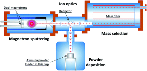
To address these issues, the experimental apparatus has been redesigned and reconstructed. Fig. 1 shows the schematic of the modified system used for the current work.
The system consists of four sections: (1) a magnetron sputtering section; (2) an ion optics section; (3) a mass filter section; and (4) a powder deposition section. Within the magnetron sputtering section metal atoms are sputtered out of the magnetron target, and these atoms are subsequently cooled down and condensed to form clusters of various sizes. Because of the nature of plasma sputtering, a good proportion of the clusters produced are ionised. After they leave the magnetron sputtering chamber via a small nozzle (5 mm in diameter), the clusters of positive charge are accelerated and steered by the ion optical electrostatic lenses which sit in the second vacuum chamber. In the next step, the ion beam is focused into the third vacuum chamber for mass selection. By using the Birmingham Time-of-Flight mass filter,17 the mass distribution of clusters can be monitored in real time. The neutral fraction present in the cluster beam is rejected by the mass filter.
The cluster size distribution is influenced by the aggregation length, sputtering gas (Ar) flow rate, condensation-assisting gas (He) flow rate, and temperature and pressure inside the condensation chamber. While tuning these parameters, the cluster size distribution is closely monitored using the TOF mass filter. When the desired cluster size distribution within the sampled ion beam is achieved, the high voltages applied to the deflector in the centre of the ion optics chamber are switched to deflection mode, so that the positively ionised fraction of the cluster beam is bent vertically downwards. The beam thus enters the powder deposition chamber, eventually depositing onto the particulate support material (gamma-alumina powder, HP14-150, Sasol) loaded inside a cup, which is constantly agitated to maximise exposure of all the particles. A high voltage can be applied to the cup in order to control the impact energy of a cluster landing on the support. This is so-called ‘size-controlled’ cluster deposition. Although the ‘size-controlled’ clusters deposited on the powder substrate have a much broader size distribution than those of the fully ‘size-selected’ clusters which are collected after mass selection, the throughput (i.e. material flux) of the former is about 100 times that of the latter, i.e. ∼100 μg h−1versus 1 μg h−1. This new approach has made it possible to produce one catalyst sample in about 10 hours – rather than in 1000 hours!
To produce alloy clusters, specifically Pd/Ti and Pd/Sn, two magnetrons were mounted in the magnetron sputtering chamber. The sputtering power on each magnetron was individually controlled, to influence the average metal ratio in the resulting alloy clusters. For all the cluster samples, the DC magnetron power was chosen between 5 W and 10 W, except that about 20 W power was used for Ti, which has a much lower sputtering yield than the other metals.
The vacuum system was first pumped down to a base pressure of 2.0 × 10⁻⁶ mbar with the combination of a rotary pump and a turbo-molecular pump. The walls of the cluster condensation chamber were cooled with liquid nitrogen to enhance cluster growth, taking about two hours to reach base temperature. For sputtering, the argon gas flow rate was 80 sccm, and a 20 sccm flow of helium gas (for condensation) was also admitted into the condensation chamber. An aggregation length of 24 cm between the sputtering target(s) and the exit nozzle was used for all the cluster samples.
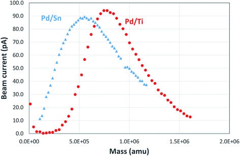
Fig. 2 shows an example of the mass spectra observed for Pd/Sn and Pd/Ti clusters. The Pd/Sn alloy cluster distribution has a peak at a mass of ∼500k amu; the corresponding mass is 750k amu for Pd/Ti clusters. It is estimated that both types of clusters have a similar diameter, around 5 nm, assuming quasi-spherical structures. Approximately the same particle size was measured using TEM analysis (see below) of the supported catalysts produced. Of course, from the mass spectra alone one cannot determine the composition of the cluster, specifically, the ratio between the two metals.
2.2 Preparation of conventional catalyst materials as references
To assess the suitability of the cluster beam materials as catalysts, reference catalysts are required. However, PdSn and especially PdTi catalysts are difficult to make using conventional routes such as impregnation or deposition–precipitation. For example, the lack of a readily-available water-soluble titanium precursor means that aqueous-based methods, desirable from environmental and economic standpoints, are not possible. Thus, the reference materials made are representative formulations but were synthesised by chemical routes which would be difficult to operate at any meaningful manufacturing scale.Palladium–tin catalysts were prepared by co-impregnation of palladium acetate with tin(II) acetate. Although this is not a typical synthesis method for palladium–tin catalysts, it avoids the use of corrosive halides. In this synthesis, the appropriate amounts of palladium acetate and tin acetate were dissolved in THF (tetrahydrofuran). The volume of the solution was calculated to match the pore volume of the support. Alumina powder (HP14-150, Sasol) was added to the solution with stirring. The resulting wet solid was air dried, then dried at 100 °C overnight, and finally reduced in flowing hydrogen at 250 °C for two hours.
Palladium–titanium catalysts were prepared by co-impregnation of palladium acetate and titanium tetraisopropoxide in THF. This is a system which would be somewhat challenging for manufacturing, with THF chosen as a solvent for both metal precursors. The need for an organic solvent arises from the lack of simple water-soluble titanium precursors. The appropriate amounts of palladium acetate and titanium tetraisopropoxide were dissolved in THF, with the solution volume again being chosen to match the support pore volume. Alumina powder (HP14-150, Sasol) was added to the solution in one portion with stirring. The resulting wet solid was air dried, then dried at 100 °C overnight, and then reduced in flowing hydrogen at 250 °C for two hours.
2.3 Catalyst characterisation
The metal content of the materials synthesised is reported in Table 1. The cluster beam materials contain significantly less metal than those prepared using wet chemistry.| Catalyst | Synthesis method | Palladium content/wt% | Tin content/wt% (Pd/Sn molar ratio) | Titanium content/wt% (Pd/Ti molar ratio) |
|---|---|---|---|---|
| PdSn–I1 | Impregnation | 0.96 | 3.27 (0.33) | — |
| PdSn–I2 | Impregnation | 0.94 | 1.01 (1.0) | — |
| PdSn–I3 | Impregnation | 1.07 | 0.36 (3.3) | — |
| PdSn–C1 | Clusterbeam | 0.09 | 0.06 (1.7) | — |
| PdSn–C2 | Clusterbeam | 0.15 | 0.12 (1.4) | — |
| PdSn–C3 | Clusterbeam | 0.09 | 0.05 (2.0) | — |
| PdTi–I1 | Impregnation | 0.88 | — | 1.05 (0.38) |
| PdTi–I2 | Impregnation | 0.89 | — | 0.61 (0.66) |
| PdTi–I3 | Impregnation | 1.10 | — | 0.15 (3.3) |
| PdTi–C1 | Clusterbeam | 0.053 | — | 0.11 (0.22) |
| PdTi–C2 | Clusterbeam | 0.041 | — | 0.0075 (2.5) |
| PdTi–C3 | Clusterbeam | 0.09 | — | 0.01 (4.1) |
| PdTi–C4 | Clusterbeam | 0.0085 | — | 0.008 (0.48) |
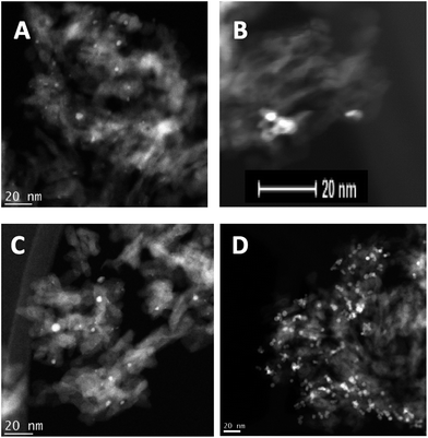
Transmission electron microscopy (TEM) coupled with energy-dispersive X-ray spectroscopy (EDX) has been used extensively to understand the local structure of the catalysts. Fig. 3 shows representative images of the Pd–Sn and Pd–Ti catalysts. TEM shows that the nanoparticles are better dispersed through the support in the case of the “conventional” (impregnated) sample PdSn–I2, compared with the cluster beam material PdSn–C2, where the clusters appear to be aggregated. For the Pd–Ti catalysts, the cluster beam sample PdTi–C3 presents more discrete particles than the impregnated material PdTi–I2.
X-ray photoelectron spectroscopy (XPS) was used to gain information about the chemical composition of the catalyst’s surface. Although the spectra were inevitably dominated by the alumina support, it was still possible to measure the palladium, tin and titanium in the samples. Table 2 shows the surface elemental compositions as measured using XPS. The chemical environments of Pd, Sn and Ti are similar when comparing the impregnated and cluster beam materials. Palladium is present as a metal whilst both tin and titanium are found as oxidic species. While both tin and titanium are assembled as metal nanoparticles in the cluster beam technique, they will be oxidised as a result of exposure to air when the materials are removed from the apparatus.
| Catalyst | Synthesis method | Binding energy/eV | Surface atomic ratios | |||
|---|---|---|---|---|---|---|
| Pd 3d | Sn 3d | Ti 2p | Pd/Sn | Pd/Ti | ||
| PdSn–I2 | Impregnation | 335.6 | 487.3 | — | 0.38 | — |
| PdSn–C2 | Clusterbeam | 335.2 | 486.5 | — | 0.77 | — |
| PdTi–I2 | Impregnation | 335.2 | — | 458.6 | — | 0.37 |
| PdTi–C3 | Clusterbeam | 335 | — | 458 | — | 3.3 |
3 Catalyst performance
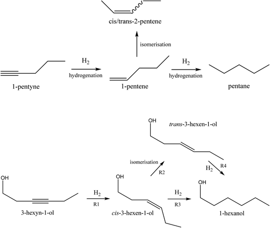
The catalysts were evaluated in the selective hydrogenation of alkynes to alkenes. Two reactions were selected: the vapour-phase hydrogenation of 1-pentyne and the liquid phase hydrogenation of 3-hexyn-1-ol. The aim of these reactions is to hydrogenate the alkyne to the corresponding alkene, but without further hydrogenation to the alkane, or isomerisation of the double bond. The reaction schemes are shown in Fig. 4. A wide range of metals are active for these hydrogenation reactions, such as nickel, cobalt, copper, platinum, ruthenium, rhodium and palladium.19 Of these, palladium is typically chosen for fine chemicals applications because of its superior performance despite its higher cost.The selective hydrogenation of alkynes to the corresponding alkene is of interest to the bulk as well as fine chemicals sectors. In the bulk chemical industry it is applied to the purification of ethylene streams by removal of acetylene impurities.20 These impurities are typically present at very low levels. The catalyst is required to hydrogenate the acetylene selectively to ethylene without over-hydrogenation to ethane. Also it must not hydrogenate the ethylene which makes up the main part of the gas mixture. In the fine chemicals industry, selective hydrogenation is used in many different ways to effect functional group interconversions in complex molecules. In this context, very high selectivity is again required along with tolerance of other functional groups.21 In this work, we use the selective hydrogenation of 1-pentyne and 3-hexyn-1-ol as model reactions for both types of scenario. Additionally, the selective hydrogenation product of 3-hexyn-1-ol, cis-3-hexen-1-ol, is a fragrance compound used in the perfumery industry.
3.1 Results for 1-pentyne selective hydrogenation
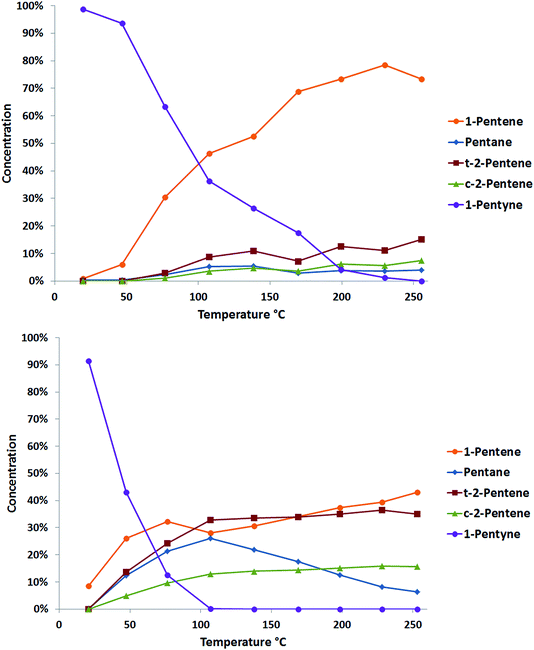
The selective hydrogenation of pentyne was performed using a fixed bed reactor. 10 mg of catalyst was held between two plugs of quartz wool and placed into a furnace. The gas feed consisted of 40% H2/He at 250 ml min−1 and 1 M pentyne solution in n-hexane, with 0.5 M iso-hexane as an internal standard, at 0.06 ml min−1. Once flushing was complete, the catalyst was heated to 250 °C at 2 °C min−1. Analysis was performed at different temperatures using an online GC.Typical data acquired from two catalysts prepared by cluster beam deposition, PdTi/γ-Al2O3 and Pd/γ-Al2O3, are shown in Fig. 5. Both catalysts show good activity for the reaction, with complete conversion of the 1-pentyne feedstock. The monometallic palladium catalyst shows some selectivity to 1-pentene, but the levels of pentane (from overhydrogenation) and the cis and trans 2-pentene (from isomerisation) are also high. These latter reactions are thought likely to occur on the reactive sites on the alumina support.22 The palladium–titanium catalyst behaves similarly. It is less active, complete conversion of the 1-pentyne feedstock requires a higher reaction temperature. Interestingly, the side-reactions to the 2-pentene isomers and to pentane are suppressed, giving a higher selectivity to 1-pentene. This could be caused by a number of factors: an electronic interaction between palladium and titanium; the presence of titania in the palladium particles leading to a better palladium dispersion; a direct interaction of the reactants with titania; or a bimetallic palladium–titania active site for the reaction.
Fig. 6 compares the performance of a range of catalysts produced via cluster beam and conventional methods. It can be seen that the palladium–tin catalysts do not offer good performance in 1-pentyne hydrogenation. The materials prepared by impregnation are only selective at a low conversion, while those prepared using the clusterbeam method are poorly active, even if they show some selectivity. It seems that tin is a poison for the palladium catalyst. Unlike the Lindlar palladium–lead catalyst,23 the poisoning does not lead to extra product selectivity. The palladium–titanium catalysts, on the other hand, are more promising. When prepared by impregnation, the catalysts exhibit very high activity but low selectivity. The materials prepared via cluster beam methods, on the other hand, show excellent selectivity (85–90%) to 1-pentene at high 1-pentyne conversion (over 95%). The best catalysts (top right corner of Fig. 6, which means good conversion and good selectivity) are cluster beam materials. Whilst the low loading of the cluster beam samples could be a factor (this is currently under investigation) – and certainly makes catalyst characterisation more difficult – it is likely that the catalyst structure arising from the cluster beam synthesis method also impacts positively on the performance.
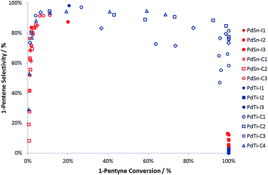 | ||
| Fig. 6 Summary of 1-pentyne hydrogenation performance for PdSn and PdTi catalysts. Note that the data arises from experiments performed at a range of temperatures from room temperature to 250 °C. | ||
3.2 Results for 3-hexyn-1-ol selective hydrogenation
Selective hydrogenation of 3-hexyn-1-ol was carried out using a Chemscan reactor. This consists of eight small autoclaves (8 ml volume), which can be run in parallel, with monitoring of hydrogen uptake. Each autoclave was filled with catalyst (24.5 mg) and 0.5 M 3-hexyn-1-ol solution in ethanol (5 ml) with 0.5 M 1,4-dioxane as the internal standard. The autoclave was pressurised to 3 bar with hydrogen, and the reaction temperature was 30 °C. The reaction time was 90 minutes, which was generally enough time to allow complete conversion to 3-hexen-1-ol. The reactions were analysed by hydrogen uptake rate and also by offline GC analysis at the end of the reaction.Four main reactions occur during the catalysis: the desired hydrogenation of 3-hexyn-1-ol to cis-3-hexen-1-ol (R1), the isomerisation of the cis isomer to trans-3-hexen-1-ol (R2), and the hydrogenation of the cis-(R3) and trans-(R4) alkenes to 1-hexanol. This is summarised pictorially in Fig. 4. Three apparent reaction rates were derived from the experimental data: the rate of hydrogenation of 3-hexyn-1-ol to cis-3-hexen-1-ol (R1), calculated from the hydrogen uptake data; the rate of 1-hexanol formation from both cis- and trans-3-hexen-1-ol (R3 + R4), again calculated from hydrogen consumption data; and the rate of formation of trans-3-hexen-1-ol from cis-hexen-1-ol less the rate of its loss through hydrogenation to 1-hexanol (R2–R4), calculated from GC analysis. Note that all three rates assume that the hydrogenation to cis-3-hexen-1-ol is complete before any further reactions occur. Our previous work has found this to be a reasonable assumption.
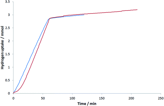
Fig. 7 and Table 3 show a comparison between two cluster beam catalysts: a monometallic Pd/Al2O3 catalyst and a bimetallic PdTi/Al2O3 catalyst (PdTi–C1). The titanium-containing catalyst shows slightly more activity for the desired alkyne hydrogenation and less for the undesired hydrogenation to 1-hexanol. The isomerisation activity of the titanium-containing catalyst is a little higher, which could be due to the close proximity of Pd and Ti sites. It is interesting to note in Fig. 7 that there is a short induction period at the start of the reaction when the PdTi–C1 catalyst is used. This could be related to the reduction of the palladium before hydrogenation begins. As it is not present when the monometallic palladium catalyst is used, it seems that the presence of titanium slows this reduction.
| Catalyst | R1/μmol min−1 gcat−1 | R3 + R4/μmol min−1 gcat−1 | R2–R4/μmol min−1 gcat−1 |
|---|---|---|---|
| Pd/Al2O3 | 2041 | 102 | 135 |
| PdTi/Al2O3 | 2286 | 69 | 147 |
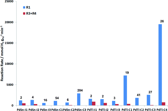
Fig. 8 presents a summary of the performance of the catalysts tested. An ideal catalyst would have a high rate for R1 (blue bar) and a low rate for (R3 + R4) (red bar). In this reaction, the cluster beam materials show a much greater selectivity for 3-hexen-1-ol than the impregnated materials. For the PdSn materials, the catalysts prepared via impregnation are more active than those prepared via the cluster beam route. However, the cluster beam materials are more selective, and for the most selective cluster beam material the overhydrogenation reaction is almost completely eliminated. Tin can act as a selective poison for palladium in selective hydrogenation in a similar manner to the Lindlar catalyst.5 This advantage of the cluster beam materials over the conventional materials is even more pronounced in the case of the PdTi catalysts. All three of the impregnated materials are very poorly selective to the alkene, with the rate of alkene hydrogenation being similar to the rate of alkyne hydrogenation. The cluster beam materials offer much better selectivity to 3-hexen-1-ol regardless of their Pd/Ti ratio. Good catalytic performance in this reaction has previously been reported for monometallic palladium nanoparticles, albeit at lower hydrogen pressure, which will tend to reduce the amount of overhydrogenation observed.24 However, the cluster beam technique allows PdSn and PdTi catalysts to be made which exhibit superior performance, especially the PdTi clusters.
3.3 Discussion of selective hydrogenation results
It is clearly of interest to understand the origin of the good performance (especially selectivity) observed in alkyne hydrogenation by the cluster beam materials. When a catalyst is prepared via impregnation, the metal salt contacts the support, which allows ion exchange to occur. The nature and number of these ion-exchange sites will depend on the nature of the metal and the support, but they will be different from the main nanoparticle sites. Having a second reaction site of uncontrolled structure is likely to be detrimental to selectivity. When catalysts are synthesised via the cluster beam method, and thus the nanoparticles are synthesised away from the support, the metal only contacts the support in a metallic nanoparticle form. This means that ion exchange cannot occur. A similar phenomenon can be observed when using nanoparticles synthesised via solution routes, but one key benefit of the cluster beam method is the absence of stabilising ligands, so the nanoparticles are deposited cleanly onto the support.In summary, we have shown that novel catalyst compositions can be readily synthesised using the cluster beam method, including those which are difficult to access by conventional “wet chemistry” approaches. The method makes active catalysts for a range of industrially relevant catalytic processes, as illustrated here by two selective hydrogenation reactions, and in some cases creates materials which outperform those synthesised following conventional methods.
4 Outlook: further scale-up of cluster beam production with the matrix assembly cluster source (MACS)
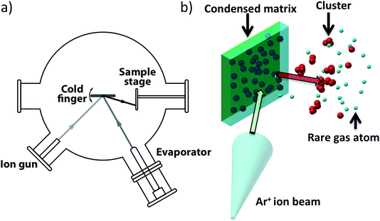
The catalysis results presented in Section 3 demonstrate the promise of cluster beam materials for catalyst research but such experiments would be greatly assisted by further scale up of the rate of cluster beam production. The preparation of the catalysts evaluated in Section 3 depended on the modification of the cluster beam source (Section 2): extraction of clusters before the mass selection stage resulted in a hundred times more flux. In this section, we report briefly on the demonstration of a new kind of cluster beam source, developed in the Birmingham lab, which offers the prospect of a further rise in cluster beam flux by several more orders of magnitude. The new source is based on the assembly of clusters inside a condensed inert matrix, assisted by ion beam bombardment of the matrix. The ion beam also sputters clusters out of the matrix to make the cluster beam which is deposited on the support. The source is termed the “Matrix Assembly Cluster Source”, or (MACS).25Fig. 9(a) is a schematic of the MACS instrument; the principle of operation is shown in Fig. 9(b), which depicts inert gas (Ar) atoms and atoms of the cluster material (Ag) condensed together to form a composite matrix on a solid metal plate cryogenically cooled to <25 K in a high vacuum chamber. Some of the metal atoms will diffuse and form small clusters by aggregation in the matrix but in order to grow these clusters to a larger size and to extract them from the matrix, an (argon) ion beam is used to bombard the matrix. The ion impact injects energy into the matrix, initiating a cascade of collisions leading to cluster growth and also sputtering out from the matrix clusters formed inside the matrix.26 These ejected clusters form the cluster beam which is collected on amorphous carbon TEM grids for analysis by High Angle Annular Dark Field Scanning Transmission Electron Microscopy (HAADF STEM).
We refer to the geometry shown in Fig. 9 as “reflection mode”, in contrast to the “transmission mode” (this employs a semi-transparent grid as the matrix support).25 The matrix employed in the present work was prepared with a concentration of 1.6% Ag atoms in an argon matrix. The Ar gas was dosed through a leak valve, with an Ar pressure of 5 × 10⁻⁶ Torr, and Ag was evaporated at the same time at a deposition rate of 0.05 Å s−1 for 200 s. The matrix was subsequently sputtered with an Ar+ ion beam (2.5 keV, 6 μA Ar+) for 30 seconds.
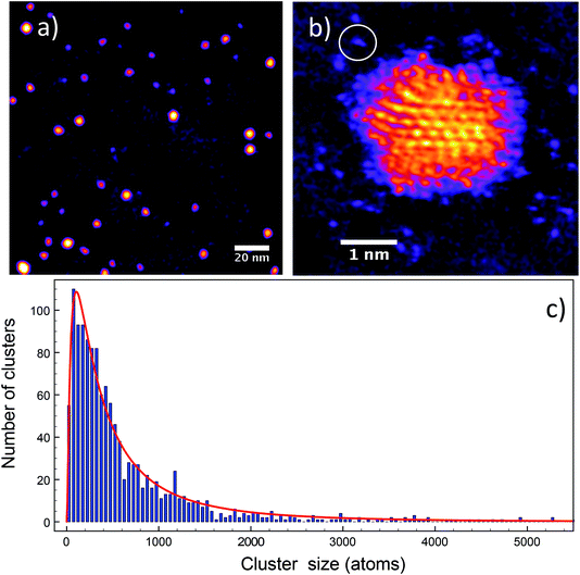
Fig. 10 shows the HAADF STEM images of the Ag clusters produced with the MACS and deposited onto TEM grids. Fig. 10(a) shows an array of clusters and Fig. 10(b) a close-up view of one of them. The intensities of the clusters in these images allow measurement of their size distribution via the atom counting method.27–30 We used the average intensity of single atoms as a reference. The cluster size distribution of Fig. 10(c) has a peak between 100 and 150 silver atoms. The half width at half maximum is about 100% of the peak cluster size, which is only about ±33% in terms of diameter (as more commonly quoted in catalyst work). Thus, although no mass filtering stage is employed in the present work, the size distribution is quite narrow in comparison with conventional methods of catalyst particle synthesis.
We obtained an equivalent cluster beam current of ∼28 nA for a 3 μA ion beam current incident on the matrix, giving a cluster yield per incident ion of close to 1%. The “equivalent cluster beam current”, which pretends that each cluster bears a single charge, is chosen to compare the flux with the output of conventional cluster sources (Section 2), but the clusters we collect on the TEM grids may have any, or no, charge. To demonstrate that scale up (and sustained operation) of the MACS method is feasible, we investigated the generation of clusters with a higher ion beam current of 30 μA over a period of 4.5 minutes in a different vacuum chamber. In this case, the Ag concentration in the matrix was 1.8%. Clusters were deposited into a carousel able to present 21 glass slides (75 mm × 25 mm), or equivalent surfaces, to the beam. The maximum equivalent beam current achieved was 210 ± 36 nA and a relatively stable flux was obtained at the 100nA level.
In both demonstration experiments the efficiency (number of clusters per incident atomic ion) approaches 1%. Since large area commercial ion guns are available with currents of more than 1 A, it should be possible to produce several more orders of magnitude of the cluster flux in MACS. Ultimately, a cluster current of 10 mA (1% of 1 A) would be equivalent to about 10 g of clusters per hour, or 1 kg of catalyst (loaded at 1% metal) per hour, sufficient for small batch pharmaceutical work. The demonstration experiments reported here are sufficient to demonstrate that the principle of the MACS is valid and indeed already exceeds the flux reported in Section 2.
5 General conclusions
The research reported here demonstrates some of the advantages of the cluster beam approach in the study of model catalysts under realistic reaction conditions and is made possible by innovations in cluster beam source design, which enable the scale-up of the cluster beam flux and the direct deposition of clusters onto powder supports. We have demonstrated favourable combinations of efficiency and selectivity for binary metal clusters in both liquid and gas phase hydrogenation experiments, when compared with catalysts prepared via conventional routes. Moreover, the new MACS technology offers at least the prospect of several more orders of magnitude of cluster beam flux, to the point where small scale manufacturing of commercial catalysts may become feasible in the foreseeable future. No doubt, however, much further innovation will be required to reach that point.Acknowledgements
We thank Innovate UK (formerly the Technology Strategy Board), EPSRC and the Leverhulme Trust for financial support of this project. The STEM employed in this work was provided by the Birmingham Science City project funded by AWM and the ERDF. We are grateful to the following colleagues at Johnson Matthey for their analytical work: Laura Stead and Matthew Rose (ICP); Tugce Erlap Erden and Richard Smith (XPS); Gregory Goodlet, Dogan Ozkaya and Winson Kuo (TEM). The MACS concept is the subject of the following patent applications: Palmer, R. E., (2011) Provisional GB Patent Application GB1113168.7; (2012) PCT Patent Application PCT/GB2012/051854; (2014) Europe Patent Application EP12753793.4; (2014) China Patent Application CN201280048410.2; (2014) Japan Patent Application JP2014-523387; (2014) U.S. Patent Application US14/236386.References
- J. Grunes, J. Zhu, E. A. Anderson and G. A. Somorjai, J. Phys. Chem. B, 2002, 106(44), 11463–11468 CrossRef CAS.
- I. Lee, R. Morales, M. A. Albiter and F. Zaera, Proc. Natl. Acad. Sci. U. S. A., 2008, 105(40), 15241–15246 CrossRef CAS PubMed.
- E. C. Tyo and S. Vajda, Nat. Nanotechnol., 2015, 10, 577–588 CrossRef CAS PubMed.
- M. Arenz, U. Landman and U. Heiz, ChemPhysChem, 2006, 7(9), 1871–1879 CrossRef CAS PubMed.
- R. E. Palmer, S. Pratontep and H.-G. Boyen, Nat. Mater., 2003, 2(7), 443–448 CrossRef CAS PubMed.
- F. Yin, S. Lee, A. Abedela, S. Vadja and R. E. Palmer, J. Chem. Phys., 2011, 134, 141101 CrossRef PubMed.
- F. Yin, C. Xirouchaki, Q. Guo and R. E. Palmer, Adv. Mater., 2005, 17(6), 731–734 CrossRef CAS.
- F. Yin, Z. W. Wang and R. E. Palmer, J. Am. Chem. Soc., 2011, 133(27), 10325–10327 CrossRef CAS PubMed.
- P. Hernandez-Fernandez, F. Masini, D. N. McCarthy, C. E. Strebel, D. Friebel, D. Deianan, P. Malacrida, A. Nierhoff, A. Bodin, A. M. Wise, J. H. Nielsen, T. W. Hansen, A. Nilisson, I. E. L. Stephens and I. Chorkendorff, Nat. Chem., 2014, 6(8), 732–738 CAS.
- C. Holse, C. F. Elkjaer, A. Nierhoff, J. Sehested, I. Chorkendorff, S. Helveg and J. H. Nielsen, J. Phys. Chem. C, 2015, 119(5), 2804–2812 CAS.
- W. A. de Heer, Rev. Mod. Phys., 1993, 65(3), 611–676 CrossRef CAS.
- S. Pratontep, S. J. Carroll, C. Xirouchaki, M. Streun and R. E. Palmer, Rev. Sci. Instrum., 2005, 76(4), 045103–045109 CrossRef.
- A. T. Bell, Science, 2003, 299(5613), 1688–1691 CrossRef CAS PubMed.
- C.-J. Jia and F. Schuth, Phys. Chem. Chem. Phys., 2011, 13, 2457–2487 RSC.
- J. A. Lopez-Sanchez, N. Dimitratos, C. Hammond, G. L. Brett, L. Kesavan, S. White, P. Miedziak, R. Tiruvalam, R. L. Jenkinsm, A. F. Carley, S. Knight, C. J. Kiely and G. J. Hutchings, Nat. Chem., 2011, 3, 551–556 CrossRef CAS PubMed.
- H. Haberland, M. Mall, M. Moseler, Y. Qiang, T. Reiners and Y. Thurner, J. Vac. Sci. Technol., A, 1994, 12(5), 2925–2930 CAS.
- B. von Issendorff and R. E. Palmer, Rev. Sci. Instrum., 1999, 70(12), 4497–4501 CrossRef CAS.
- I. M. Goldby, B. von Issendorff, L. Kuipers and R. E. Palmer, Rev. Sci. Instrum., 1997, 68(9), 3327–3334 CrossRef CAS.
- M. W. Tew, M. Nachtegaal, M. Janousch, T. Huthwelker and J. A. van Bokhoven, Phys. Chem. Chem. Phys., 2012, 14, 5761–5768 RSC.
- F.-M. McKenna, R. P. K. Wells and J. A. Anderson, Chem. Commun., 2011, 47, 2351–2353 RSC.
- A. F. Kyle, P. Jakubec, D. M. Cockfield, E. Cleator, J. Skidmore and D. J. Dixon, Chem. Commun., 2011, 47, 10037–10039 RSC.
- J. Medema, J. Catal., 1975, 37, 91–100 CrossRef CAS.
- A. K. Ghosh and K. Krishnan, Tetrahedron Lett., 1998, 39(9), 947–948 CrossRef CAS.
- J. C. A. A. Roelofs and P. H. Berben, Chem. Commun., 2004, 970–971 RSC.
- R. E. Palmer, L. Cao and F. Yin, Rev. Sci. Instrum., 2016, 87, 046103, DOI:10.1063/1.4947229.
- R. Smith, Atomic and ion collisions in solids and at surfaces: theory, simulation and applications, Cambridge University Press, 2005 Search PubMed.
- N. Young, Z. Li, Y. Chen, S. Palomba, M. Di Vece and R. E. Palmer, Phys. Rev. Lett., 2008, 101, 246103, DOI:10.1103/PhysRevLett.101.246103.
- Z. W. Wang, Z. Y. Li, S. J. Park, A. Abdela, D. Tang and R. E. Palmer, Phys. Rev. B: Condens. Matter Mater. Phys., 2011, 84, 073408, DOI:10.1103/PhysRevB.84.073408.
- Z. W. Wang, O. Toikkanen, F. Yin, Z. Y. Li, B. M. Quinn and R. E. Palmer, J. Am. Chem. Soc., 2010, 132, 2854–2855 CrossRef CAS PubMed.
- N. Jian, C. Stapelfeldt, K. J. Hu, M. Fröba and R. E. Palmer, Nanoscale, 2015, 7(3), 885–888 RSC.
| This journal is © The Royal Society of Chemistry 2016 |

