
 Open Access Article
 This Open Access Article is licensed under a Creative Commons Attribution-Non Commercial 3.0 Unported Licence
An overview of advances in biomass gasification
Vineet Singh
Sikarwar
a,
Ming
Zhao
*abc,
Peter
Clough
d,
Joseph
Yao
d,
Xia
Zhong
e,
Mohammad Zaki
Memon
a,
Nilay
Shah
d,
Edward J.
Anthony
f and
Paul S.
Fennell
*d
aSchool of Environment, Tsinghua University, Beijing 100084, China. E-mail: ming.zhao@tsinghua.edu.cn; Tel: +86 10 62784701
bKey Laboratory for Solid Waste Management and Environment Safety, Ministry of Education, Beijing 100084, China
cCollaborative Innovation Center for Regional Environmental Quality, Tsinghua University, Beijing 100084, China
dDepartment of Chemical Engineering, Imperial College London, South Kensington, London SW7 2AZ, UK. E-mail: p.fennell@imperial.ac.uk; Tel: +44 (0)20 7594 6637
eSchool of Chemical & Biomolecular Engineering, The University of Sydney, Sydney NSW 2006, Australia
fCranfield University, Cranfield, Bedfordshire MK43 0AL, UK
First published on 2nd June 2016
Abstract
Biomass gasification is a widely used thermochemical process for obtaining products with more value and potential applications than the raw material itself. Cutting-edge, innovative and economical gasification techniques with high efficiencies are a prerequisite for the development of this technology. This paper delivers an assessment on the fundamentals such as feedstock types, the impact of different operating parameters, tar formation and cracking, and modelling approaches for biomass gasification. Furthermore, the authors comparatively discuss various conventional mechanisms for gasification as well as recent advances in biomass gasification. Unique gasifiers along with multi-generation strategies are discussed as a means to promote this technology into alternative applications, which require higher flexibility and greater efficiency. A strategy to improve the feasibility and sustainability of biomass gasification is via technological advancement and the minimization of socio-environmental effects. This paper sheds light on diverse areas of biomass gasification as a potentially sustainable and environmentally friendly technology.
 Vineet Singh Sikarwar | Vineet Singh Sikarwar is a PhD researcher working in the Laboratory for Biomass Energy & CCS Technologies, School of Environment, Tsinghua University for the past 2 years. He is working on experimental and theoretical investigations of biomass gasification with CO2 capture under the supervision of Dr Ming Zhao. He has pursued his Bachelor's and Master's degrees in Mechanical Engineering from Rajiv Gandhi Technical University India with focus on Renewable Energy Systems. |
 Ming Zhao | Ming Zhao is an associate professor in the School of Environment at Tsinghua University. He obtained his PhD in Chemical Engineering from the University of Sydney in 2010. He was elected into China's Recruitment Program of Global Youth Experts (The National Youth 1000–Talent Program) after he completed his work at Imperial College London in 2014. He is now the director of the Laboratory for Biomass Energy & CCS Technologies. The research interests of his group include thermo-chemical conversion of solid fuels (e.g. coal and biomass) into clean energy and value-added chemicals, advanced materials and processes for CO2 capture, modelling study for fuel processing, waste-to-energy and CCS processes, and LCA-based techno-economic assessment towards commercialization. |
 Nilay Shah | Nilay Shah is the Director of the Centre for Process Systems Engineering (CPSE) and co-director of the Urban Energy Systems project at Imperial College London. His research interests include the application of process modelling and mathematical/systems engineering techniques to analyze and optimize complex, spatially- and temporally-explicit low-carbon energy systems, including hydrogen infrastructures, carbon capture and storage systems, urban energy systems and bioenergy systems. He is also interested in devising process systems engineering methods for complex systems such as large scale supply chains and bio-renewable processes, and in the application of model-based methods for plant safety assessment and risk analysis. He has published widely in these areas and is particularly interested in the transfer of technology from academia to industry. |
 Edward J. Anthony | Dr Anthony is the head of the Combustion and Carbon Capture and Storage Centre at Cranfield University and a Professor in Energy Process Systems. Previously he was a senior research scientist with Natural Resources Canada, where he headed the Gasification and Fluidized Bed Combustion Group. His interests include thermal energy processes that can offer pure CO2 streams for sequestration, and gasification technology, both in its high-pressure and atmospheric forms. Dr Anthony is the author of 215+ journal papers on various aspects of combustion and gasification, along with a similar number of conference papers, 13 book chapters, and he is the co-editor of the first book on Pressurized Fluidized Beds and a new book with Dr Paul Fennel on Ca and Chemical Looping. Dr Anthony's current R&D pursuits are strongly focused on calcium looping cycles, oxy-fired CFBC technology and pressurized, entrained-flow gasification and lime-based chemistry. Dr Anthony was an adjunct Professor with the Chemical Engineering Department at the University of Ottawa from 2005 to 2013, and is a guest Professor with Southeast University in Nanjing, China and a visiting Professor at Imperial College. He is also a Fellow of the Institution of Chemical Engineers, the Royal Society of Chemistry and the Institute of Energy and he is a Chartered Scientist, and a Chartered Engineer. |
 Paul S. Fennell | Paul Fennell is a Reader in Clean Energy at Imperial College London. He obtained his degree in Chemical Engineering and PhD from the University of Cambridge. He chaired the Institution of Chemical Engineers Energy Conversion subject panel (2014–2016), and has acted as an advisor for numerous UK government departments. He is the joint director of IC's Centre for Carbon Capture and Storage and is the Research Area Champion for Industrial CO2 Capture and Storage for the UK CO2 Capture and Storage Research Centre. He has published 50+ papers since 2005 and is the 2015 winner of the IChemE Ambassador prize. |
Broader contextBiomass energy is one of the most widely explored research fields in energy and environmental science. The major driver for biomass gasification research is to exploit low-cost feedstocks, to increase process efficiency, decrease installation and operational costs and socio-environmental effects. This work gives a holistic view of current research, development and deployment, and how we could move forward towards economically and socially acceptable biomass gasification technologies. We elucidate various areas and compare various conventional gasification technologies, current developments, and challenges to advance gasification as a viable and environmentally sustainable technology for using renewable fuel resources. |
1. Introduction
Alterations to the climate due to temperature rise caused by the greenhouse effect pose a risk to humanity, and other species. Greenhouse gas (GHG) emissions from anthropogenic activities such as the burning of fossil fuels for power generation are major contributors to climate change. This necessitates a switch from conventional to renewable power sources, for example, solar photovoltaic (PV), wind, biomass and hydroelectric generation. Biomass utilization has an advantage over other renewable sources as it is less dependent on location and climate and biomass is easily storable and transportable. In addition, it is abundantly available, currently provides more than 10% of the global energy supply, and ranks among the top four energy sources in terms of world final energy consumption in 2011.1–3Rural areas in underdeveloped nations are dependent upon biomass for essential activities such as cooking and heating. India has substantial coal reserves of around 223 billion tonnes, but these are concentrated in specific locations (central and eastern India) unlike biomass, which is evenly and extensively spread over the whole nation.4,5 Furthermore, waste biomass is often more readily available and can be equally as useful as a low-cost fuel. This makes it viable and promising as an energy source. Developed countries are also focusing on biomass as a sustainable energy option since it is abundant and has a lower environmental impact compared to fossil fuels.
An interesting account of global gasification history can be found in the National Energy Technology Laboratory, USA database and investigation performed by Rajvanshi.6,7 The earliest research on gasification was done by Thomas Shirley in 1659. His investigation led to the production of carbureted hydrogen, presently known as methane. In 1739, Dean Clayton moved a step forward and distilled coal in a closed vessel. The earliest patents in gasification were acquired by Robert Gardner and John Barber in the years 1788 and 1791 respectively. Robert Gardner investigated the usage of waste thermal energy of furnaces to generate steam by burning the products in a boiler. John Barber's patent was about the usage of producer gas to run an internal combustion (IC) engine. However, the first confirmed application of producer gas from coal was reported in 1792 when William Murdoch produced gas from coal to light his residence. The 19th century saw the exploitation of the water–gas shift reaction in 1801 by Fourcroy, and installation of the first successful gasifier unit, the Siemens gasifier, in 1861. The 20th century witnessed groundbreaking development. Fully continuous gasification using cryogenic separation of air was contrived by Carl Linde in 1920. This was followed by the development of the fluidized bed gasifier (FBG) in 1926 and the pressurized moving bed process in 1931. These were stepping stones in the biomass gasification (BG) arena, which led to the establishment of the first commercial gasification plant in the US in December 1999. This was a coal gasification plant known as the Wabash River Coal Gasification Project.8 Post 2001, biomass gasification has increasingly come under the spotlight, on account of rising oil prices and concerns over climate change. This led to the expansion of more advanced biomass gasification projects around the world.9–12
Biomass gasification has a high potential for application in waste processing compared to other existing techniques such as land-fill, incineration, etc., because it can accept a wide variety of inputs and multiple useful products can be produced. Biomass gasification is an intricate process involving drying the feedstock followed by pyrolysis, partial combustion of intermediates, and finally gasification of the resulting products. It is performed in the presence of a gasifying media which can be air, oxygen (O2), steam (H2O) or carbon dioxide (CO2), inside a reactor called a gasifier. The calorific value of the product gas is dependent on the gasifying agent. The product gas from air gasification gives a heating value of around 4–7 MJ Nm−3 whereas when gasifying utilizing pure O2, the heating value can be as much as 12–28 MJ Nm−1.13 Biomass gasification reduces the carbon-to-hydrogen (C/H) mass ratio resulting in increased calorific content of the product on account of enhanced H2 fraction.14 The gasifying medium also plays a vital role of converting solid char and heavy hydrocarbons (HC) to low-molecular-weight gases such as carbon monoxide (CO) and H2. The quality and properties of the product are dependent on the feedstock material, gasifying agent, feedstock dimensions, temperature and pressure inside the reactor, design of reactor and the presence of catalyst and sorbent.15
There are many useful products from the gasification of biomass, which include: syngas, heat, power, bio-fuels, fertilizer and bio-char. Syngas can be further processed by means of the Fischer–Tropsch process into methanol, dimethyl ether and other chemical feedstocks. Generally, biomass feedstocks are classified into four main groups: woody biomass, herbaceous biomass, marine biomass and manures.16 The gasifier is usually designed to generate a given product; however, the feedstock material is an important parameter to specify and optimize where possible.
Tar formation during biomass gasification is a serious problem. Tar is a thick and viscous liquid containing heavy aromatic hydrocarbons and often a high content of heavy metals.17 It has the potential to cause operational issues through downstream blockage and quality degradation of product gas. Furthermore, tars are never the desired product and thus the efficiency of production is reduced. Tar can be reduced by thermal cracking, steam reforming, dry reforming, carbon formation and partial oxidation as presented in reactions (1), (2), (3), (4) and (5), respectively.
| pCnHx ⇆ qCmHy + rH2 | (1) |
| CnHx + mH2O ⇆ nCO + (m + x/2)H2 | (2) |
| CnHx + nCO2 ⇆ 2nCO + (x/2)H2 | (3) |
| CnHx ⇆ nC + (x/2)H2 | (4) |
| CnHx + (n/2)O2 ⇆ nCO + (x/2)H2 | (5) |
In the above series of reactions, CnHx represents tar, which is the combination of numerous organic compounds, and CmHy represents a lighter HC compared to CnHx.18 The work presented here also reviews various research related to the formation, quantification, growth and minimization of tar production.
The goal of this review is to assess conventional and advanced biomass gasification technologies. In the next section we compare conventional and emerging designs to characterize the current state of the art and classify encouraging novel technologies. In Section 3, we discuss feedstocks and the effects of feedstock properties on system performance. Section 4 explains the influence of various operating parameters on the gasification process and Section 5 discusses various dimensions of tar formation, measurement and minimization. It is followed, in Section 6, by discussion of various multi-generation approaches, including potential barriers. This paper also sheds light on the various mathematical modelling techniques such as thermodynamic modelling, kinetic modelling, computational fluid dynamics (CFD), artificial neural network modelling (ANN), and their associated limitations, along with tar models. The social and environmental impact of biomass gasification (hereafter BG) is also discussed in the last section.
2. Biomass gasification – conventional vs. emerging
Over the past decade, biomass gasification has been developed to utilize wastes and to obtain useful products such as syngas, H2, methane (CH4) and chemical feedstocks. These gases can additionally be produced from biomass through biochemical routes. Thermochemical pathways have an edge over the other routes, as commercialized biochemical processes currently have issues treating biomass rich in lignocellulose9 (importantly, new methods to valorize lignocellulosic biofuels are under development, but currently are not commercialized at full scale, e.g. the ionosolv19 and organosolv20 treatment methods). In addition, they operate in batch mode, are relatively slow and produce a dilute product stream, with large amounts of water recirculating in the processes. The thermochemical route also has the advantage of being able to accommodate a more diverse range of biomass.21 Moreover, it has a higher efficiency and a lower cost.22 One of the main limitations with this process is the small range of products.21,22The most commonly used gasifiers are fixed bed gasifiers (FXBG), fluidized bed gasifiers (FBG) and entrained flow gasifiers (EFG). These are shown in Fig. 1(a), (b), 2 and 3, respectively. The difference between updraft and downdraft is shown in Fig. 1(c). Briefly, a fixed-bed gasifier can be either updraft (fuel enters from the top, gasifying agent from the bottom) or downdraft (both fuel and gasification agent enter from the top), with the fuel coming in from a lock-hopper. In updraft gasification, the char at the bottom of the bed meets the gasifying agent first, and complete combustion occurs, producing H2O and CO2 and raising the temperature to ∼1000 °C. The hot gases percolate upwards through the bed, driving endothermic reactions with unreacted char to form H2 and CO, with consequent cooling to ∼750 °C. The gases pyrolyze the dry biomass which is descending, and also (near the top of the reactor) dry the incoming biomass. Updraft gasifiers typically produce between 10 and 20 wt% tar in the produced gas, which is far too high for many advanced applications.10
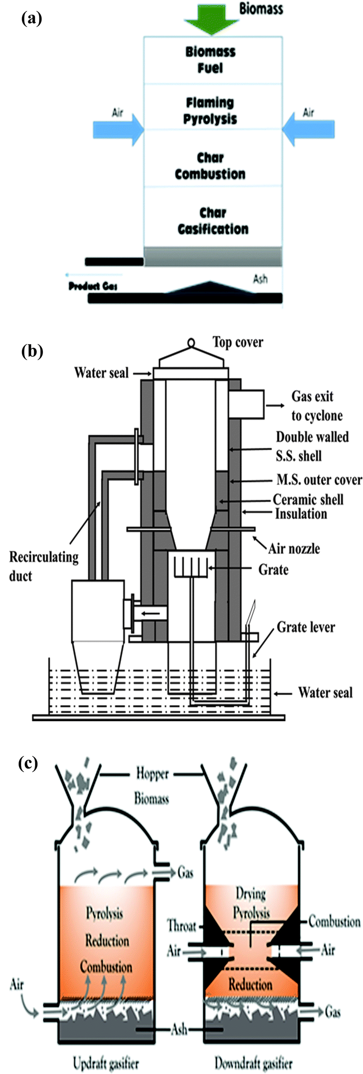 | ||
| Fig. 1 (a) Schematic diagram of conventional fixed bed gasifier (downdraft).28 (b) Open-top gasifier (downdraft).27 (c) Difference between updraft and downdraft fixed bed gasifiers. | ||
 | ||
| Fig. 2 Schematic diagram of a conventional fluidized bed gasifier (circulating).28 | ||
 | ||
| Fig. 3 Schematic diagram of an entrained flow gasifier (side-fed).28 | ||
The allowable tar levels depend on the downstream application. These are around 0.05 g Nm−3, 0.005 g Nm−3 and 0.001 g Nm−3 for gas engines, gas turbines and fuel cells, respectively.23 In contrast to an updraft gasifier, in a downdraft gasifier (closed top) the gas flows co-currently with the fuel. A “throated” gasifer has a restriction part-way down the gasifier where air or O2 is added, and where the temperature rises to 1200–1400 °C, and the fuel feedstock is either burned or pyrolyzes. The combustion gases then pass down over the hot char at the bottom of the bed, where they are reduced to H2 and CO. The high temperature within the throat ensures that the tars formed during pyrolysis are significantly cracked (homogeneous cracking), with further cracking occurring as the gas meets the hot char on the way out of the bed (heterogeneous cracking), leading to a less tarry off-gas. Some disadvantages of a throated gasifier are:9
• The constriction at the throat affects the types of biomass that can be successfully gasified.
• A low moisture content is required (<25 wt%).
• Ash and dust are significantly present in the exhaust.
• Tar can still be up to 5 g Nm−3, needing further clean-up.
Another interesting and efficient design for fixed bed was devised by the scientists of the Indian Institute of Science.24–27 This open top fixed bed reactor has been found to be more efficient and reliable especially with high moisture content feedstock and produces a high quality gas with low tar content. The gasifier consists of a vertical tube with an open top and water seal at the bottom, as depicted in Fig. 1(b). The top third of the reactor is made of stainless steel, with an annular jacket around it. The remaining lower part is made of ceramic material to avoid high-temperature corrosion (>600 °C) caused by the different gases prevailing at that point in the gasifier. The hot combustible gases produced are taken to the upper annulus of the gasifier via a grate and an insulated pipe. These gases transfer the heat to the feedstock, aid in drying and enhance the thermal efficiency of the process. A re-circulating duct connects the upper annular part of the gasifier to the lower part and is insulated with alumino-silicate blankets. Constant homogeneous air flow through the bed resulting in a final fuel-rich state enhances the gasifier performance. Furthermore, a superior quality syngas with lower tar content is obtained on account of gas movement through a deep hot bed of charcoal.27 Currently, there are more than 40 combined heat and power (CHP) plants based on this design operating worldwide.24
Fluidized bed gasifiers come in three basic types:
■ Bubbling fluidized bed (BFB): here, the biomass is fed from the side, and/or below the bottom of the bed, and the gasifying agent's velocity is controlled so that it is just greater than the minimum fluidization velocity of the bed material. The product gas exits from the top of the gasifier and ash is either removed from the bottom or from the product gas using a cyclone.
■ Circulating fluidized bed (CFB) systems use two integrated units. In the first unit (the riser) the bed material is kept fluidized by the gasifying agent, with a higher velocity than that found in a BFB. This allows the bed material to be fluidized to a greater extent than in the BFB and the overall residence time is higher, due to the circulation, which is effected by passing the product gas and entrained bed material through a cyclone which separates the product gas from the bed material which is recirculated back to the riser.
■ Dual fluidized bed (DFB) gasifiers separate the gasification and the combustion parts of the process using two separate fluidized beds. The biomass is fed into the base of the gasifier bed, usually fluidized by steam. The second bed acts as a char combustor using air in a fast fluidized bed which heats the bed material. The bed material acts as the heat transfer medium between beds and this avoids gas transfer, allowing a nitrogen-free syngas to be produced; the bed material is separated from the combustion flue gases in a cyclone and recirculated to the gasifier.
Entrained flow gasifiers are highly efficient and useful for large-scale gasification, and are commonly employed for coal, biomass and refinery residues. Their requirement for highly pulverized fuel particles presents problems when gasifying biomass. On the other hand, gasification in these gasifiers is above 1000 °C which aids in cracking tar; they are therefore advantageous for biomass gasification where tar is a serious issue. They are basically classified in two families:
■ Top-fed gasifier: these are vertical reactors of cylindrical shape where finely refined particles of fuel and gasifying agent are fed from the top end in the form of a jet. An inverted burner results in their combustion followed by gasification. Product gas is taken out from the side of the lower section whereas slag is deposited at the bottom of the reactor.
■ Side-fed gasifier: here, pulverized fuel and the gasifying agent are fed through nozzles present in the lower part of the reactor. This design results in appropriate mixing of fuel and oxygen. The product gas is collected from the top and the slag from the bottom of the vessel.
Other important issues that process designs need to deal with are slagging, fouling and corrosion. These issues arise out of the inorganic species present in the biomass and are, therefore, dependent to a large part on the biomass composition. Corrosion can occur from the generation of acid gases in the gasification process, which in turn have their origin in species such as sulphur and chlorine. Corrosion concerns may require temperature management (e.g., rapid cooling of the syngas while maintaining it above the acid dew points), active maintenance strategies or attention to materials of construction or coatings. Slagging and fouling are dependent on the ash content of the biomass, and the propensity for these problems is also related to the alkali metal content of the biomass, as explained in Section 3.1.
Among advanced approaches is the concept of unique gasifiers which integrate biomass gasification, a pollutant removal process, and gas conditioning within a single reactor. This reduces space requirements resulting in lower investment costs.29 An analysis of other strategies such as multistage gasification, pyrolysis and gasification at different locations, supercritical water gasification (SCWG) and plasma gasification30 are also presented in this section of the review.
2.1 Conventional approaches
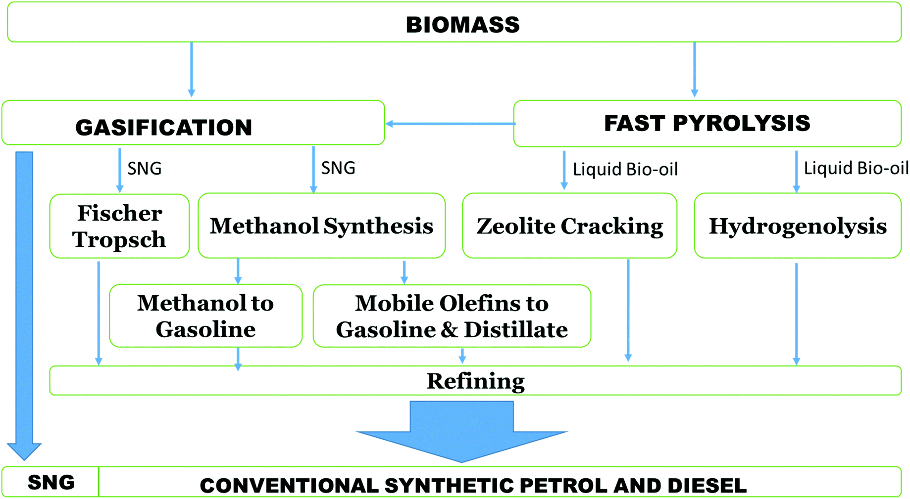
Biomass gasification consists of many overlapping processes: drying, pyrolysis and partial oxidation. The feasible gasification routes are shown in Fig. 4. Pyrolysis is the process of producing solid, liquid or gaseous fuels or valuable chemicals by transforming biomass in an O2-deficient environment. The process can be categorized as mild pyrolysis, slow pyrolysis or as fast pyrolysis. A very simple way of representing the gasification reaction is shown below (6):| Biomass → H2 + CO + CO2(g) + HC(g) + Tar(l) + Char(s) | (6) |
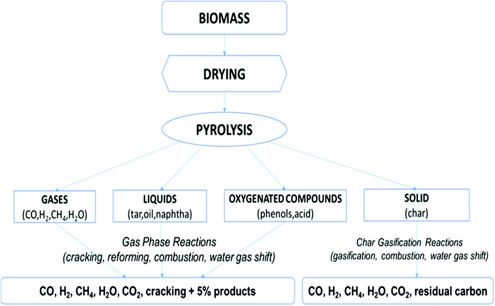 | ||
| Fig. 4 Gasification routes.31 | ||
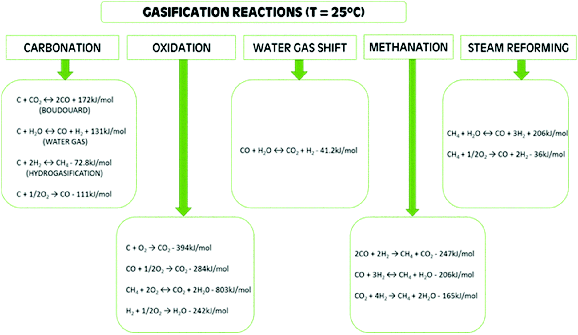 | ||
| Scheme 1 Gasification reactions.12,14,32 | ||
Steam gasification is an efficient and established method for H2 production.36,37 The char and tar production is small since the steam transforms them to CO and H2 through gasification, water–gas shift and reforming reactions. Several researchers38–41 have established that the H2 yield through steam BG is three times higher than the yield from air BG. They have also reported an improvement in cost-effectiveness with higher H2 production while using steam as the medium in gasification. Aravind et al.42,43 state that gas cleaning is a vital step between gas production in the gasifier and gas utilization. The outlet gas exiting the biomass gasification system is contaminated with tar, alkali metals, particulate matter, nitrogen (N2), sulphur (S), and chlorine (Cl). Table 1 shows the issues caused by these contaminants and methods to eliminate them.
| Contaminant | Example | Issue | Removal technique |
|---|---|---|---|
| Particulate | Ash, char | Erosion | Cyclone, filter, ESP |
| Tar | Cyclic & polycyclic hydrocarbon | Clogging, deposition | Physical, chemical & catalytic methods |
| Alkali metal | Sodium & potassium compounds | Hot gas corrosion | Gas cooler + cyclone/ESP |
| Fuel nitrogen | NH3, HCN | NOx | Scrubbing |
| Sulphur | H2S, SO2 | Corrosion | Scrubbing, activated carbon |
| Chlorine | HCl | Corrosion, catalyst poisoning | Scrubbing, activated carbon |
Contaminants such as particulates, tars, nitrogenous compounds such as NH3 and HCN, sulphur-containing inorganic compounds such as H2S, COS and CS2, halogens such as HCl and Cl, and traces of metals such as Na and K are present in varying quantities in syngas produced from gasification. As compared to other contaminants, tar is present in huge quantities per unit wt of feedstock.46 The type of biomass, operational conditions and the gasifier type are the variables which determine tar concentrations. These contaminants in syngas pose numerous technical and working problems. For example, H2S is responsible for equipment corrosion, tar causes fouling and catalyst deactivation occurs due to tar, H2S, NH3, HCl and trace metals.47–49 The maximum permissible limits of contaminants, for various applications, present in syngas from biomass gasification are depicted in Table 2.
| Contaminants | Applications | ||
|---|---|---|---|
| Gas turbine | FT synthesis | Methanol synthesis | |
| Tar (mg Nm−3) | na | <0.1–1 | <1 |
| Sulphur contaminants (ppmv) | <20 | 0.01 | <1 |
| Nitrogen contaminants (ppmv) | <50 | 0.02 | 0.1 |
| Alkali (ppmv) | <0.02 | 0.01 | na |
| Halides (ppmv) | <1 | 0.01 | 0.1 |
2.2 Emerging approaches
Currently, in biomass gasification plants, clean gas is produced at ambient temperature after filtration and scrubbing, limiting its applications. The reduction in gas temperature owing to cleaning followed by conditioning reduces the overall profitability of the plant (although the syngas cooling step generates high-quality steam which can be of use elsewhere in the process or exported depending on the setup). Moreover, if the tar separation is not very effective, the gas quality and yield will suffer, making it unfit for applications where high levels of purity are essential. Therefore, gas conditioning preceded by clean-up at elevated temperatures (i.e., “hot gas cleanup”, HGCU) is necessary, to ensure high efficiency in industrial applications, especially in the case of steam gasification. An example is NETL's sorbent-based cleanup process.50 Progress in catalysts, sorbents and filtration techniques operating at high temperatures have paved a way to integrate gasification and gas clean-up in one reactor. Unique gasification technology investigated by research and development (R&D) establishments and industries in Europe and the US has made it possible to have immediate and efficient conversion of the outlet gas. They are used in fuel cells and micro gas turbines along with power plants.3 An example of a novel HGCU process is the use of plasma torches to crack tars; this differs from plasma gasification where the plasma is used for energy generation by gasifying biomass, MSW and refuse derived fuel (RDF).51,52 Relevant features, advantages and limitations of these technologies are presented in Table 3.| Strategy employed | Features | Advantages | Limitations |
|---|---|---|---|
| Combination of gasification and gas clean-up in one reactor | Integration of gasification of biomass feedstock and syngas cleaning in single reactor |
• Robust process design
• Cost-effective |
More research is needed for large-scale commercial applications |
| Multi-staged gasification concept | Execution of pyrolysis and gasification within divided zones in a gasifier, in single-controlled stages |
• High quality clean syngas generation
• Improved process efficiency |
Enhanced complexity |
| Integration of distributed pyrolysis plants with central gasification plant | Production of char-oil slurry in distributed pyrolysis plants and gasification in central plant for syngas generation and biofuel synthesis |
• Usage of distributed, low-grade biomass
• Cost-effective transportation of char-oil slurry |
Gasoline and olefins production via this process is not economical |
| Plasma gasification | Usage of plasma as a heat source during gasification or as a tar-cracking agent downstream |
• Decomposition of any organic matter
• Treatment of hazardous waste |
• High investment cost
• High power requirement • Low efficiency |
| Super critical water gasification | Gasification is carried out in super-critical water |
• Liquid and biomass with high moisture content are treated
• No pre-treatment is required |
• High energy requirement
• High investment cost |
| Sorption enhanced reforming and biomass gasification with CO2 capture | Gasification of feedstock is performed in the presence of catalyst and sorbent |
• In situ CO2 capture
• Enhanced H2 production • Reduced tar content |
Development of advanced catalysts cum sorbents is needed |
| Co-generation of thermal energy with power | Combined generation of heat and power | Enhanced process efficiency | Only decentralized heat and power production is feasible as heat needs to be produced near the consumer |
| Poly-generation of heat, power and H2 | Combined generation of heat, power and H2 |
• Enhanced process efficiency
• Generation of renewable H2 |
Enhanced complexity in process design |
| Poly-generation of SNG with heat and power | Combined generation of heat, power and SNG |
• Generation of renewable fuel for transportation
• Enhanced process efficiency |
Not economical in the absence of a natural gas distribution system |
| FT process coupled with gasifier | Syngas generated via gasification is utilized for FT-fuels synthesis | Production of clean, carbon-neutral liquid biofuels | Enhanced complexity in process design |
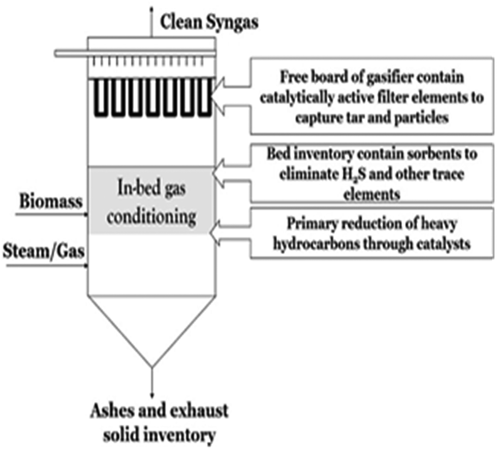 | ||
| Fig. 5 Schematic of unique combination of gasification with in situ gas cleaning and conditioning.3 | ||
The presence of tars is considered the most inconvenient problem to deal with, especially while operating large-scale BG systems. Traditionally, steam reforming at elevated temperatures is employed as the solution.55,56 A FBG with low-cost bed material which can also act as catalyst to reduce the requisite temperature for tar cracking in the presence of steam is a viable alternative.55,56 The catalyst not only has a strong selectivity for the desired gas product, but it also has a high resistance to attrition and carbon deposition. A detailed discussion on tar abatement is given in Section 5.3 in this paper.
A very large volume of research has been conducted using dolomite and/or olivine as the catalyst bed material for the catalytic tar cracking. Calcined dolomite (CaMg(CO3)2), limestone (CaCO3) and magnesite (MgCO3) are reported to enhance H2 yield.57–61 Rapagna et al.,13 Corella et al.62 and Devi et al.63 demonstrated that dolomite shows a higher reactivity for BG towards tar reforming compared to olivine, but it is more susceptible to attrition. Nickel-based (Ni) catalysts suffer from mechanical instability, rapid deactivation in the presence of S, alkali metals and Cl, and sintering. On the other hand they allow the system to achieve higher H2 yields.64 Interestingly, it has been reported that when olivine was impregnated with Ni, the aforementioned issues with Ni-based catalysts were alleviated substantially.56,65,66 Olivine impregnated with iron (Fe) has also been tested. The results showed different catalytic mechanisms which were dependent on the extent of integration with Fe into their corresponding crystalline structure.67 Calcination of Fe-bearing olivines has been reported to form oxides whose amount is dependent upon calcination time and temperature.67,68 Rapagna et al.41 and Virginie et al.69,70 found that when 10 wt% Fe-olivine was utilized in a pilot gasifier instead of olivine alone, total gas yield was increased by 40%, H2 yield by 88%, CH4 was curtailed by 16% and tar generation by 46%, encouraging the accretion of Fe in olivine.
The research above has shown that Ni-catalysts are suitable to convert tarry fuel gas into clean syngas even if hydrogen sulphide (H2S) is present.71 In most of the cases, catalytic activity is slightly reduced; however, the residual activity remained constant even after considerable operation time and complete transformation of naphthalene, which is a key component of tar, was achieved.72,73 Ni-based catalysts have also been examined using a model gas (a mixture of benzene, naphthalene and CH4) treatment, employing a catalytic filter.71–73 High H2S concentrations are a serious risk for downstream chemical synthesis and fuel cell applications below 1000 °C.42 Ca-based sorbents have a high affinity for H2S at elevated temperatures. The sulphidation of calcined and non-calcined CaCO3 was examined extensively by Hu et al.74,75 Elseviers et al.76 carried out extensive experimental work in real life settings for H2S removal, and with simulated coal gas.76–78 They concluded that fuel gas composition does not influence the desulphurization performance of the sorbents.
Various studies have been conducted to assess the influence of sorbents on H2S, hydrochloric acid (HCl) and other elements such as alkali and heavy metals, in a new concept called the Unique gasifier as shown in Fig. 5.3 Stemmler et al.79 investigated the effects of varying the inlet feedstock and gasifier temperatures using thermodynamic models applying Gibbs free energy minimization on the elimination of alkali metals and toxic gases. Some experimental work was also carried out to back the theoretical findings. It was established that the contaminants are removed in downstream equipment, giving a supplementary advantage of enhanced tar reforming.3 Aluminosilicates are reported to degrade alkali species' concentrations to ppb levels, along with the elimination of Cl and zinc (Zn).80,81
The major problem with alkali and other heavy metals is their condensation and consequent induction of fouling and corrosion. Barisano et al.82 reported the utility of aluminosilicate sorbents to eliminate alkali halides during gasification. They used a FBG operating at ambient pressure with bauxite to degrade potassium chloride and sodium chloride. Bauxite was the preferable choice as it, along with bentonite, kaolinite and naturally occurring zeolites, is abundantly available, cheap and does not have a negative environmental impact on disposal.
An atypical gasification strategy separates pyrolysis and biomass gasification into separate stages with individual control, which are then subsequently integrated, i.e., a multistage gasification. It avoids mixing of produced volatiles and char, consequently adverse impacts on the reactivity and gasification of char are eradicated. Enhanced exit gas purity, char transformation rate and efficiency, coupled with low levels of tar formation, can be achieved when employing this strategy. Two distinct modes of operation have been applied by the Danish Technical University, Denmark, and Karlsruhe Institute of Technology, Germany.84,85 In the first method, pyrolysis and biomass gasification are integrated in either a 2- or 3-stage process with different stages combined in a single overall unit with separated pyrolysis or biomass gasification zones or different reactors utilized in succession. In the other method, pyrolysis plants are positioned at diverse locations near sources of biomass pyrolysis. The pyrolysis products are transported to a central biomass gasification unit, thus improving the energy density of the energy vector transported, and hence the supply chain economics. Energy density is markedly enhanced when biomass is transformed to pyrolytic oils or oil – char slurry. For example, the energy densities of straw and woodchips is 2 GJ m−3 and 8 GJ m−3, respectively while in pyro-oil and char-oil slurry, the density increases to 30 GJ m−3 and 26 GJ m−3.86 This concept is described in the following section – Integration of distributed pyrolysis plants with central gasification plant.
Multi-staged gasification concept. Pyrolysis and gasification are executed within divided zones inside a gasifier. This enables biomass conversion into usable products to take place under optimized operational settings for each individual step. The main motive behind this concept is to obtain a high-quality clean syngas with a low tar content. Moreover, improved efficiency and larger throughput have resulted utilizing this multi-zoned reactor setup.3
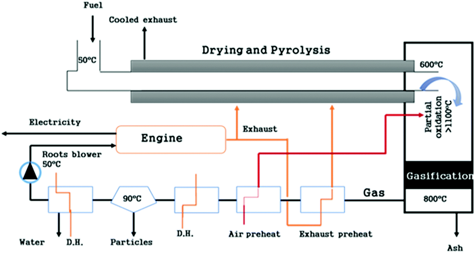
Some examples of this split reactor operation include the 75 kWth Viking gasifier installed at the Danish Technical University; the FLETGAS process developed at the University of Sevilla, Spain; and a low-temperature circulating fluidized bed (LT-CFB) by DONG Energy Company in Denmark.83,84,87 As shown in the Fig. 6, the Viking gasifier is a 2-stage unit with a screw pyrolysis reactor followed by a downdraft gasifier. Material exiting the pyrolysis reactor is mixed with air to partly oxidize it before it enters the biomass gasification reactor. This degrades the tar content in the product gas to less than 15 mg m−3 (s.t.p.). Exit gases from the gasifier contain around 32% H2 and 16% CO with traces (2%) of CH4 with an upper calorific content of gas of 6.6 MJ Nm−3.84,88 This gasifier is presently working at 200 kWe and will soon be up-scaled to 500 kWe.89
 | ||
| Fig. 6 Schematic diagram of Viking gasifier.84 | ||
The FLETGAS process is a 3-stage gasification system. Devolatization in a FBG takes place with low transformation of tar and char between 700 °C and 750 °C, in the first stage, with high production of reactive tar. The reactive tar is then reformed with steam in the second stage at 1200 °C. Char generated in the first step undergoes gasification in a downdraft gasifier, which in turn forms the third stage. Char formed in the primary step is directly conveyed to the third stage via solid transport in a sealed system and gas coming from the second step passes into the bed of char, which also serves as catalyst for further tar reduction.83,90
Researchers have performed modelling work to investigate the advantages and disadvantages of multi-staged reactors over single-stage reactors. A noteworthy decline in the tar concentration to 10 mg Nm−3, coupled with char conversion of 98% and an overall excellent gasification efficiency of 81% has been simulated, prompting further investment and investigation. The higher heating value of the product was found to be 6.4 MJ Nm−3.87 This procedure is under development at pilot scale87 with continued experimental work to improve the process.91,92 The main limitation is the intricate reactor set-up which may limit its scale-up possibilities.
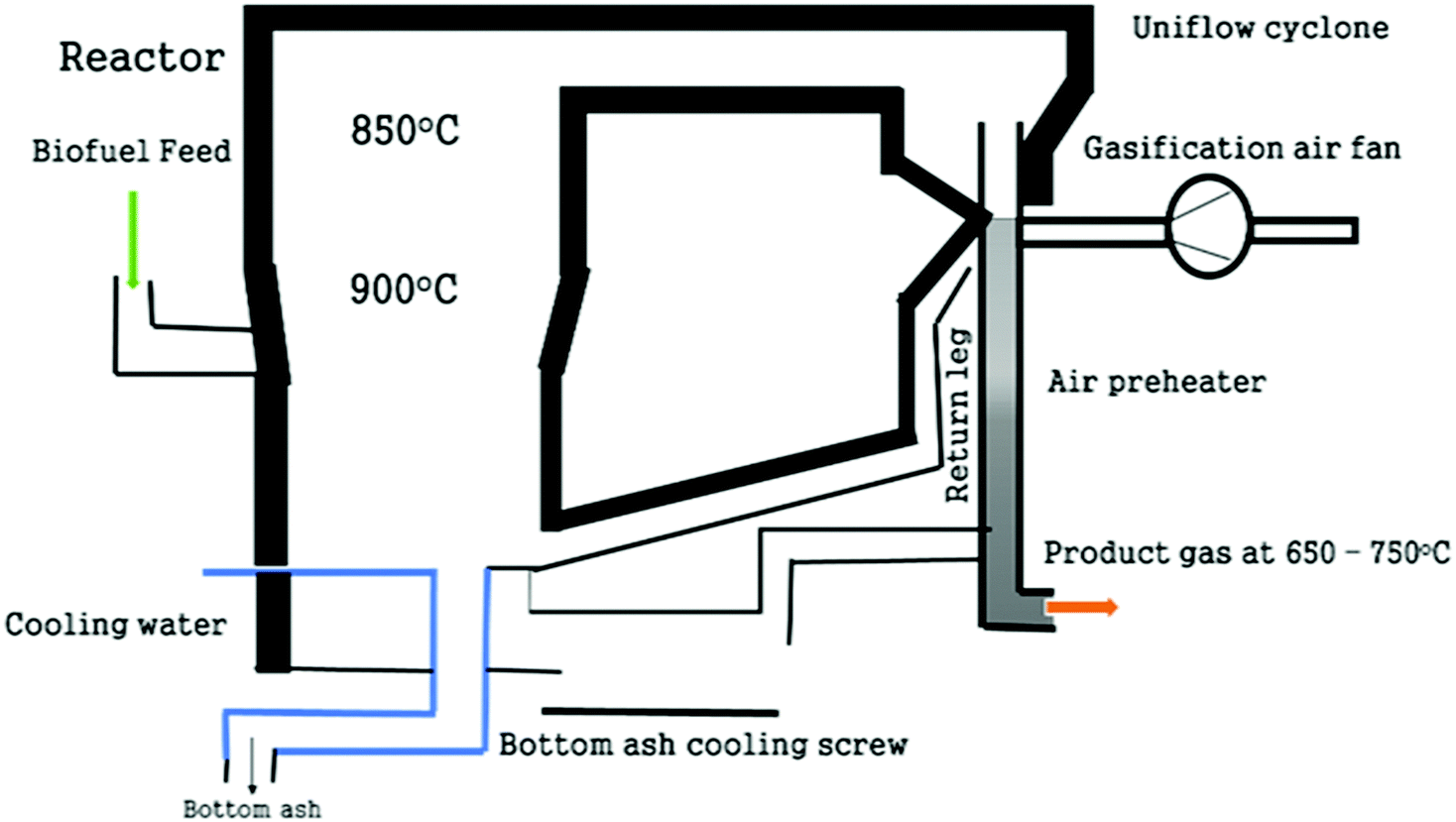
The LT-CFB gasifier has two inter-connected stages with a circulating fluidized bed pyrolysis reactor operating at around 650 °C in the first stage and a bubbling FBG operating at 730 °C in the second stage for the gasification of char. This is shown in Fig. 7. A high residence time in this gasification strategy reduces the temperature required for char gasification. Sand and ash are used as the heat transfer medium, which takes the thermal energy from the lowest part of the gasifier to the pyrolysis reactor. Moreover, vaporized char in the form of gas is also redirected to the pyrolysis reactor. Char and sand are separated from the gas with the aid of the cyclone installed between the two reactors.
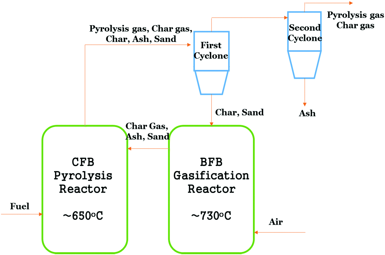 | ||
| Fig. 7 Simple schematic diagram of LT-CFB gasifier.3 | ||
The process has already been tested in 100 kWth and 500 kWth units and a demonstration plant has been installed by DONG Company at 6 MWth capacity, where the produced gas is co-fired with coal. This process was developed for challenging feedstocks such as pig manure, straw, sewage sludge, organic wastes, etc.3 The maximum calorific content of the exit gas employing pig manure as fuel, was reported as 7 MJ Nm−3 with a composition of 3.5% H2, 16.3% CO, 4.3% CH4 and 59% N2. Thomsen et al.93 found that low process temperatures are responsible for retention of alkalines in ash; however, the output gas contains high tar concentrations (>4.8 g m−3), making it less likely to be usable in most applications, without a cleaning step. This process has been found to be robust, cost effective and has low maintenance. It can be seen from the aforementioned multi-stage processes that higher char transformation and gasification efficiencies are achieved vis-à-vis single-stage biomass gasification, with an exception of the entrained flow gasifier, which is single-staged but has high oxygen requirements and limited biomass feedstock fraction allowed, as major limitations. However, the multi-stage process is significantly more complex and requires high capital investment.
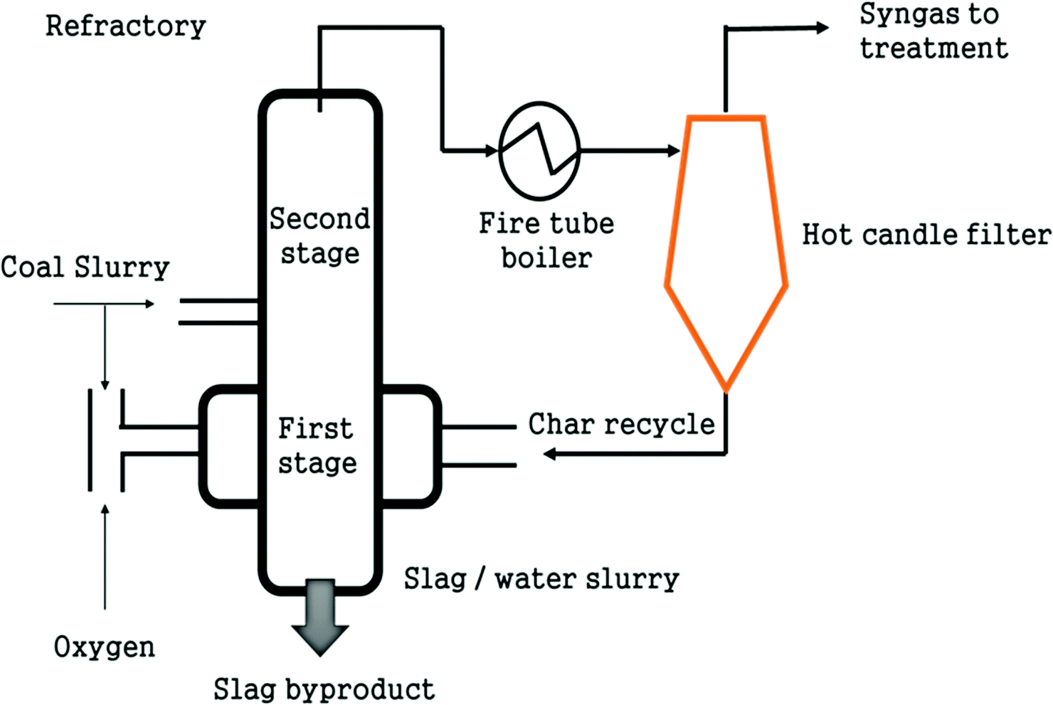
Integration of distributed pyrolysis plants with central gasification plant. The strategy to employ pyrolysis and gasification at different locations was developed in Germany as the Bioliq concept.85 Here, biomass is treated in several pyrolysis plants in different locations and then the char-oil slurry produced is transported to the centralized BG unit, for gasification and bio-fuel synthesis. The main advantage of this strategy is its ability to use distributed, low-grade ligno-cellulosic biomass coupled with the cost-effective transportation of char-oil slurry instead of the biomass itself. Biomass with an energy density of about 2 GJ m−3 is upgraded to an oil-char slurry which has an energy density of about 25 GJ m−3, which is equivalent to coal and easier to transport in tankers, for example. This enhancement in energy density is stated to make this process highly economical.94 A flow diagram depicting the Bioliq concept is presented in Fig. 8.
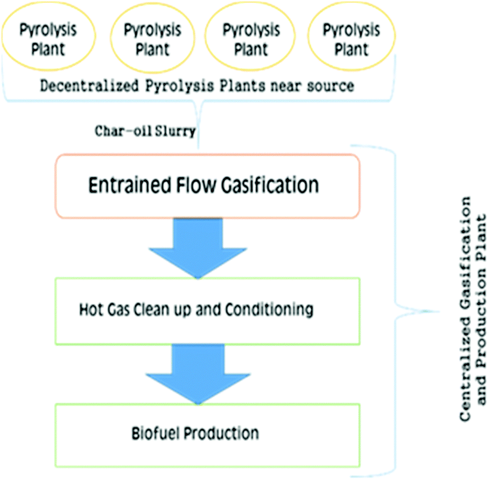 | ||
| Fig. 8 Simplified scheme of the Bioliq concept. | ||
A demonstration plant has been constructed in Germany employing 4 process steps: production of an oil-char slurry through pyrolysis at different locations, gasification of the slurry, clean-up of product gas and production of biofuel. Fast pyrolysis at 500 °C was selected for feedstock preparation for BG owing to its short reaction time and high yield.95 The slurry is then gasified with oxygen as the gasifying medium to produce 5 MWth in an EFG operating at 1200 °C with two pressure stages of 40 and 80 bar.96 This type of slurry gasification is quite novel and has been associated with the experimental investigations of the char-oil slurry coupled with the modeling of the slurry.97
Ceramic hot gas filters are installed to clean up impurities of the syngas such as alkalis, chloride, furfurals, phenols and sulphur at 800 °C.98 This is different from the conventional vertical hanging filters in a tube sheet in terms of design and position.99 The horizontal design imparts compactness along with a reduced vessel size. Chlorides and sulphurous gas components are removed by sorbents such as CaO and ZnO. Tar is subsequently cracked in the presence of catalysts. Areas for research include the changes in the properties of char-oil slurry due to stand-time, and its effect on gasification.100 Bio-oil derived from pyrolysis of biomass is a mix of furfurals, phenols with fractions of aldehydes, ketones, esters and ethers, and varying percentages of O2 and H2O, where O2 makes up 35% to 40% and H2O is 15% to 30%.101 Moreover, char-oil slurry from numerous locations is most likely to have varying composition, thus the need to test for stable atomization and uniform gasification for these slurries arises.
2.3 Special gasification techniques
Several special processes have been developed to convert different types of biomass into usable gas and/or heat and electricity.Plasma is used in two different ways in the gasification process: (1) plasma is used as a heat source during gasification; (2) plasma is used for tar cracking after standard gasification. Primarily, plasma gasification is employed for the decomposition of toxic organic wastes, along with rubber and plastics, although the first reason and currently the main application for plasma gasification is the treatment of hazardous biomass waste. However, the technology has also gained interest for syngas production and electricity generation in recent years as the costs have entered into a commercially competitive range. A plasma gasification plant at Utashinai, Japan has been operating since 2002 and as of 2014, gasifies 268 tonnes of municipal solid waste per day and thus produces 7.9 MW h electricity.102
Fig. 9 shows a plasma gasifier where the reactor chamber is connected to a non-transferred DC arc plasma torch generator.103 Due to the very high temperatures produced it can be employed for toxic wastes, rubber and plastic treatment. Energy is simultaneously produced from the BG as mentioned above for the Japanese plasma gasification unit at Utashinai. Though this concept was originally designed for municipal and other waste treatment, it was later extended for high-quality syngas generation. At elevated temperature, gasification of feedstock occurs in milliseconds.104
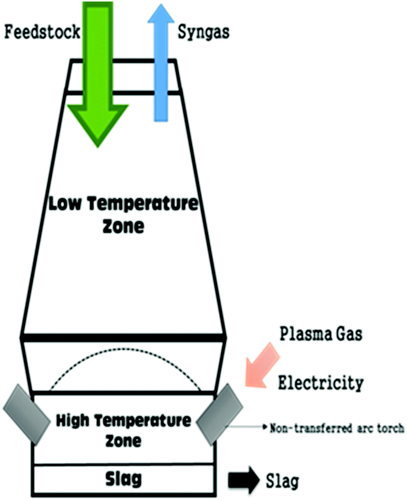 | ||
| Fig. 9 Schematic of plasma gasifier.103 | ||
The main purported benefits of this process are syngas yield with high H2 and CO content, improved heat content, low CO2 yield and low tar content.105,106 The process is employed for wet biomasses such as sewage sludge which are otherwise difficult to gasify, and minor effect of particle dimension and structure of feedstock is noted. Major limitations are high construction and maintenance costs because of the high electricity consumption to generate plasma, resulting in low overall efficiency. For instance, a base case scenario with a 680 tonne per day waste gasification plant which would be appropriate for a small town or regional facility, would cost an estimated £97 million to construct, which is almost three times the cost of other waste treatment facilities (e.g. incineration).
Rutberg et al.,107 Shie et al.108 and Tang et al.109 have investigated the plasma biomass gasification technique in detail. Plasma gasification of wood for combined heat and power was investigated by Rutberg et al.107 They used alternating current air plasma with an input power of 2.2–3.3 MJ kg−1 and produced syngas with a calorific content of 13.8–14.3 MJ kg−1. It was proved by their calculations that there is a potential to achieve 46% net electric energy conversion.
Four different biomass feedstocks – wood sawdust, wood pellets, waste plastic and oil from pyrolysis of waste tires were studied by Hlina et al.110 in a DC electric arc plasma, with 100 kW torch input power. A small quantity of argon with H2O vapor was used as the plasma gas with CO2 or H2O vapor as oxidizing medium. High-quality syngas comprising 90 vol% H2 and CO was reported for all four kinds of feedstock. Despite having high heat content of exit gases recorded for all data sets, the process efficiency is low due to the high electricity input, which is largely the limiting factor for this technology.
Janajreh et al.103 conducted non-stoichiometric chemical thermodynamic modelling for diverse biomass and compared conventional air biomass gasification with DC arc plasma gasification. Plasma gasification efficiency was stated to be 42% as compared to 72% for air gasification, on account of high energy consumption for plasma generation. Some researchers worked to decrease the high energy and investment requirements for DC arc plasma by employing microwave plasma, for carbonaceous biomass feedstocks.111–114 These investigations were performed at the lab scale ranging from 1–5 kW. Yoon et al.114 examined biomass gasification of glycerol from biodiesel production using a microwave plasma, and obtained an H2-rich syngas (57% H2, 35% CO), without any O2 feed, with a carbon conversion efficiency of 80%. Feeding O2 decreased the H2 yield and the calorific content of the gas, with an increase in CO2 content and carbon conversion. Almost the same findings were presented for coal and charcoal gasification.113 Plasma gasification has also seen some setbacks as a technology. One of the most recent was due to the City of Ottawa's decision to terminate its relationship with Plasco in February 2015, in spite of the company raising over $300 million since 2005.115 It was unable to meet its commitment to successfully operate a 150![[thin space (1/6-em)]](https://www.rsc.org/images/entities/char_2009.gif) 000 tons per annum plasma arc gasification unit. Currently, the gasification council website notes that there are functioning plasma gasifiers operating in Japan, Canada and India. Currently, Westinghouse Plasma Corporation also lists commercial operating facilities in all three countries, with a new 2000 tonnes/d MSW plant in commissioning in Tee Valley, UK and when built this will be the largest plasma gasifier unit in the world.116
000 tons per annum plasma arc gasification unit. Currently, the gasification council website notes that there are functioning plasma gasifiers operating in Japan, Canada and India. Currently, Westinghouse Plasma Corporation also lists commercial operating facilities in all three countries, with a new 2000 tonnes/d MSW plant in commissioning in Tee Valley, UK and when built this will be the largest plasma gasifier unit in the world.116
Currently, no commercial-scale H2 production plant has been reported employing plasma biomass gasification. Significant research is required to decrease energy input and thereby enhance efficiency.
SCWG has been applied to wet biomass without the need for pre-drying, which is a major advantage over other more conventional gasification techniques. Numerous investigations on diverse feedstocks such as agricultural wastes, leather wastes, switch grass, sewage sludge, algae, manure and black liquor have been performed.122–127 Employing SCWG, even liquid biomass such as olive mill water can be utilized with the production of low-tar H2 gas.124 A simplified schematic of a SCWG setup is shown in Fig. 10.
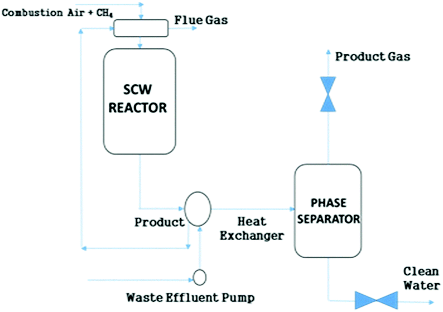 | ||
| Fig. 10 Simplified schematic of SCWG.120 | ||
Product gas from SCWG mainly comprises H2, CO2, CH4 and CO. The CO yield is comparatively low as CO transforms into CO2 through the water–gas-shift reaction.127 Tar and coke formation are curtailed by rapid dissolution of product gas components in supercritical H2O.121 Guo et al.121 and Feng et al.128 found that above 600 °C, H2 is the dominant component of the produced gas, since H2O is a strong oxidant which reacts with carbon to release H2 and CO, whereas CH4 is the main component below 450 °C. Heating of H2O to the reaction temperature necessitates a great amount of energy input. However, employing appropriate catalysts can lower the reaction temperature. This reduces the operational and equipment cost and increases conversion efficiency and H2 production. This is depicted in Fig. 11. This graph shows different gas yields vs. temperature. It reflects that H2 production enhances exponentially after 600 °C while CO increases from 500 to 660 °C and then decreases. CH4 decreases to 540 °C and then remains almost constant even when temperature is increased.
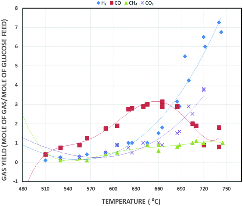 | ||
| Fig. 11 Diagram showing the variation in product distribution vs. reactor temperature in SCWG.121 | ||
A number of catalysts, such as Ni and Ru, activated carbon, Pt-based catalysts, and alkali metal-based materials such as Na3(CO3)(HCO3)·2H2O (trona), KOH, NaOH, K2CO have been tested.121,129,130 Other investigators have also studied the energy efficiency of SCWG. Biomass gasification of vinasse (a byproduct of the sugar industry) in supercritical H2O was modelled by Marias et al.131 They found a maximum efficiency of 87% at 600 °C. Lu et al.132 explained thermal losses during heat transfer at the heat exchanger, cooler, pre-heater and reactor, and demonstrated that these were responsible for the decrease in efficiency. Efficient heat exchangers may not be necessary if traces of O2 are allowed, which have been stated would make the process self-sustainable energetically at the expense of a very small loss of exit gas heating value.133
Wet biomass treatment without pre-drying, liquid biomass treatment such as olive mill waste water, high H2 yield, high gasification efficiency and low tar formation are the main benefits of SCWG.124 Major limitations include requirements of high-pressure- and high-temperature-resistant and rust-resistant materials, consequently increasing the investment costs, and high energy requirements. SCWG has been significantly improved since its initial conception and presents an interesting and possibly feasible technology especially for wet biomass but large-scale or commercial gasification requires further research.
Calcium oxide (CaO) is now an almost established catalyst to yield H2-rich product gas;39,139–142 because of its cost effectiveness and abundance,134,136,143 it has gained much attention. It acts not only as a sorbent but also as a tar cracker and heat carrier in FBG.136 Removal of CO2 during the BG process shifts the equilibrium of the product gas. This enhances the H2 yield.143 In the same manner, tar cracking increases the exit gas quantity, leading to high H2 yield and conversion efficiency.144,145 Therefore, in situ CO2 capture with CaO during the steam reforming of biomass for H2-rich gas production is highly attractive and promising.146–151
Since CaO captures CO2 according to the carbonation reaction (7), it will lead to a reduction in the partial pressure of CO2 under gasification conditions. This reduction in CO2 partial pressure drives the water–gas-shift reaction (8) forward in accordance with Le Châtelier's principle. This leads to an increased yield of H2.147 Later CaO is recovered by calcination (9). The efficacy of the reaction is a subset of other parameters also, such as steam-to-biomass ratio (S/B), temperature, pressure, and the amount of CaO.
| CaO + CO2 → CaCO3 | (7) |
| CO + H2O → CO2 + H2 | (8) |
| CaCO3 → CaO + CO2 | (9) |
In situ CO2 adsorption was studied by Pfeifer et al.152 in a dual FBG for H2-rich syngas production. They compared adsorption-enhanced reforming (AER) using CaO as bed material with traditional BG without CaO. In AER, 75 vol% H2 yield was reported with 0.5 g Nm−3 of tar at 600–700 °C whereas in the latter process, at 850 °C, 40 vol% of H2 in the product gas with 2–5 g Nm−3 was found. Hence, high H2 vol% with low tar content can be produced even at lower temperatures in the presence of CaO, thus making it a desirable choice for a sorbent in the steam reforming of biomass. AER has been studied by only a few researchers.152,153 Further research is required to explore different options to optimize energy efficiency.
A major limitation of using a CaO sorbent in steam-assisted BG is irregular H2 production due to deactivation of CaO during the regeneration. Although CaO is potentially promising in tar reforming and CO2 capture, the process would not be economically viable if the CaO could not be regenerated after the carbonation reaction. Consequently, the supply of CaO must be replenished.154 In order to overcome this problem to some extent, calcium looping gasification (CLG) was introduced. CaO-assisted CLG was first employed in the CO2 acceptor process, which was developed in the 1970s and terminated in 1977 after positive tests in a pilot plant.155 CaO-assisted CLG consists of two reactors as shown in Fig. 12. Steam reforming of biomass takes place in the gasifier in the presence of CaO, which captures CO2 and is converted to CaCO3via the carbonation reaction (7). This enhances the H2 yield. CaCO3 particles are circulated to the regenerator or combustor, where they are calcined back to CaO, with the production of a pure CO2 stream (9), which can be sent for storage. CaO is recycled back to the gasifier along with the heat of calcination which it carries and aids in compensating endothermic reactions in the gasifier.146 Therefore, this is a low-energy demanding and eco-friendly process of H2 production with enhanced efficiency of H2 production.
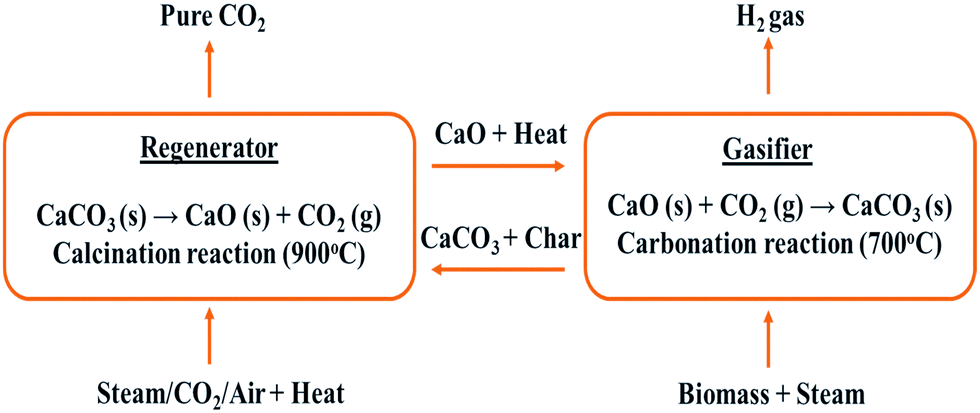 | ||
| Fig. 12 CaO looping in SER. | ||
Several researchers employed this concept of CaO-based CLG.146,152,153,156 They used a bubbling FBG, circulating fluidized bed regenerator and a cyclone. The theoretical system efficiency was reported to be 87.49% with a 71 vol% H2 yield. Moghtaderi et al.156 found, using CaO from calcined feedstocks such as dolomite that CaCO3 suffers from particle attrition and deactivation. They used construction and demolition waste (CDW) as sorbent and found high H2 yields with low CO2 in the product gas, with very limited attrition or erosion after repeated cycles.
3. Inputs and outputs
3.1 Raw material
Researchers and industry characterize feedstocks for thermochemical conversion in numerous ways. One of the simplest ways to classify them is as suggested by McKendry:16 timbered biomass, herbaceous biomass, marine plants and manures. We can further sub-categorize herbaceous plants into 2 classes – high-moisture-content plants and low-moisture-content plants. Generally, BG employs low-moisture waste to avoid the energy penalty in drying; woody biomass and herbaceous plants with low moisture contents are the primary choices because of their controllable moisture content. Biomass can also be classified as terrestrial biomass, marine biomass and waste. This classification along with sub-classification and significance is depicted in Table 4.| Classification | Sub-classification | Examples | Significance |
|---|---|---|---|
| Terrestrial16,178 | — | Forest biomass | Ideal for gasification due to high cellulose and hemicellulose percentages |
| Grasses | Non-suitable for gasification due to high moisture. Suitable for fermentation | ||
| Energy crops | Suitable for power generation through biological treatment | ||
| Cultivated crops | Some crops are ideal for gasification while others are consumed directly by humans and animals | ||
| Marine16,179,180 | — | Algae | Suitable for biological treatment because of high moisture content |
| Water plant | Ideal for biological treatment | ||
| Waste178,181,182 | Municipal waste | MSW, biosolids, sewage, landfill gas | Suitable for plasma or SCW gasification |
| Agricultural solid waste | Livestock and manures, agriculture crop residue bark, leaves, floor residues | Most suitable for composting and other biological treatments | |
| Forestry residues | Ideal for gasification albeit pre-treatment is required | ||
| Industrial waste | Demolition wood, sawdust, waste oil | Wastes like wood, sawdust are commonly employed for gasification. Others are used in biological treatments | |
Biomass feedstocks in loose or powdery form with density less than 200 kg m−3 are also promising options as raw material for BG.27 They include agricultural wastes such as bagasse, sugar cane trash, rice husk, rice straw, coir pith, groundnut shell, etc. Their calorific content varies from 12 to 16 MJ kg−1 (dry basis) with bagasse on the higher end and rice husk on the lower end, with ash content up to 20%. However, pulverization is needed prior to their usage as feedstock to enhance their bulk density and to reduce transportation cost.
Currently, sea and farmed algae have gained much attention for the generation of renewable biofuels on account of their carbon fixation potential and very high growth rate.157 Furthermore, they can easily be cultivated in seawater or fresh water. Extensive investigations performed by Shirvani et al.158 demonstrated that algae-based biofuels are more promising provided that mass production is employed. Several researchers have employed numerous varieties of micro algae such as Spirulina, Chlorella, C. vulgaris, Tetraselmis Chuii, etc. in gasification, pyrolysis, liquefaction and direct combustion. A significant volume of research related to thermochemical conversion (gasification,159–164 pyrolysis,164–167 liquefaction168–172 and direct combustion173) of algal biomass has been published.
All biomass contains cellulose, hemicellulose and lignin in varying percentages, along with an inorganic component which is the source of ash. Cellulose is a straight-chain polymer comprising anhydroglucopyranose joined with ether bonds. Hemicellulose is an amorphous polysaccharide containing sugar units which are branched and have varied sugar types. Lignin is the most complex constituent with crosslinked 3-D polymer structure of phenylpropane units.174
Proteins, starch and sugar may be extracted from biomass and separated by treatment with solvents followed by recovery through evaporation. Proteins perform diversified functions within living organisms, which include catalyzing metabolic reactions, replication and transporting molecules from one location to another.175 Granulated sugars have multiple uses in the home. Starch is a vital component in food additives, paper making, clothing starch and corrugated board adhesives.176Table 5 shows the respective compositions of some commonly gasified biomass. Their relative lignocellulose composition plays an important role in the decomposition and energy conversion while undergoing gasification.177
| Type of biomass | Cellulose (%) | Hemicellulose (%) | Lignin (%) | Other (%) |
|---|---|---|---|---|
| Softwood | 41 | 24 | 28 | 7 |
| Hardwood | 39 | 35 | 20 | 7 |
| Wheat straw | 40 | 28 | 17 | 15 |
| Rice straw | 30 | 25 | 12 | 33 |
| Bagasse | 38 | 39 | 20 | 3 |
| Oak wood | 34.5 | 18.6 | 28 | — |
| Pine wood | 42.1 | 17.7 | 25 | — |
| Birch wood | 35.7 | 25.1 | 19.3 | — |
| Spruce wood | 41.1 | 20.9 | 28 | — |
| Sunflower seed hull | 26.7 | 18.4 | 27 | — |
| Coconut shell | 24.2 | 24.7 | 34.9 | — |
| Almond shell | 24.7 | 27 | 27.2 | — |
| Poultry litter | 27 | 17.8 | 11.3 | 20 |
| Deciduous plant | 42 | 25 | 21.5 | 11.5 |
| Coniferous plant | 42 | 26 | 30 | 2 |
| Willow plant | 50 | 19 | 25 | 6 |
| Larch plant | 26 | 27 | 35 | 12 |
The cellulose, hemicellulose and lignin fractions present in biomass feedstocks degrade at different temperature ranges of 305 to 375 °C, 225 to 325 °C and 250 to 500 °C respectively during gasification.185 The variation in these constituents in biomass raw materials yields products with different calorific values. Gasification of pure cellulose yields water-soluble tars in the early stages. Interestingly, this is in contrast to full biomass gasification where lower amounts of water-soluble tars are formed.36 It seems that thermal polymerization of levoglucosan is inhibited along with the enhancement in light molecular weight species' formation from cellulose, by lignin during lignin-cellulose interactions in pyrolysis. Consequently, char yields and secondary char formation from lignin are decreased considerably as well as production of lignin-derived compounds (guaiacol, 4-vinylguaiacol and 4-methylguaiacol) are improved.186
Lv and co-authors187 studied the influence of cellulose-lignin during pyrolysis and gasification of biomass. They reported a swift reduction in mass on account of cellulose volatization during pyrolysis followed by slow mass decrease because of lignin degradation. The rate of pyrolysis is directly related to cellulose fractions and inversely dependent upon lignin content in the feedstock. Tar yields and amount of gas produced were enhanced with a decrease in char, when the cellulose fraction was increased during fast pyrolysis in FBG. Furthermore, a rise in gasification temperature and time was observed with increasing cellulose content, reflecting the significance of cellulose-lignin interactions during BG.
Extensive investigations performed by Azadi et al.188 regarding lignin gasification proved that the ultimate products (CO + H2 + CO2 + CH4) are similar to those formed during gasification of other biomass feedstocks. Ash and H2S are also included in the products via lignin gasification on account of the presence of sulphur and inorganics induced during fractionation from biomass, depending on the treatment method.
In general, the higher the cellulose and hemicellulose content, the greater the volume of gaseous products formed. Therefore, softwood, hardwood, wheat straw and bagasse with much higher cumulative percentages of cellulose and hemicellulose are preferred over sunflower seed hull, coconut shell, almond shell, larch plant or poultry litter, when attempting to obtain gas as the final product. This makes the selection of an appropriate feedstock for the desired products a vital consideration (as shown in Table 5).
Other important constituents are silica (fouling and slagging and ash disposal issues), chlorine and sulphur (acid gas mitigation) and alkali metals (slagging, fouling and high-temperature corrosion concerns).
Many researchers have conducted extensive investigations into the effects on H2 yield through non-catalytic BG of different biomass types using FBGs and UGs. Previous research has shown that in general, H2 production from gasification of biomass varies between 10 to 65 vol%.39,189–195 It is, however, difficult to assess whether the alterations are caused by the variety of biomass, type of gasifier or its operating parameters.
Characterization of feedstock is a prime factor in gasifier selection. Generally, woody biomass has an ash content below 2% and hence it is appropriate for use in a FXBG.196 This is because high-ash-content feedstocks are prone to agglomeration in FXBG during gasification, leading to a drop in conversion efficiency and possible reliability issues. An updraft-fixed-bed gasifier (UG) yields a product gas with high tar and high-volatile-content raw material, which is unsuitable for many high-purity applications like fuel cells and engines. Therefore, a DG is more fitting in this case, as simple cleaning of the outlet gases would make it practical for operation in engines. In the case of sawdust, DG can generate large tar yields, with a large pressure drop within the reactor.9 Agricultural residues such as coconut shells, maize cobs, palm kernels and other shells are commonly used as a biomass feedstock for BG, especially in under-developed countries where these materials are readily available. They are unlikely to create any problems in FXBGs. Fibrous feedstocks, such as coconut husks and empty fruit bunch are reported to create spanning problems in the feeder section, thus usually require pretreatment prior to gasification. Spanning means the material matts together because of the needle-like structure of the biomass, thus spanning and blocking the entrances to processing sections. Pretreatment can involve torrefaction or densification to avoid this problem.
Most herbaceous biomasses have high ash content and cause slagging problems in DG.197 Ash fouling during gasification is a function of gasifier operating temperature. It is observed that a low amounts of ash are released between 100 to 500 °C while ash emissions rise sharply beyond 600 °C.36 Slagging occurs because of the low melting temperature of the ash. Ca, Mg, K and Na silicates are often found to have lower melting temperatures. With temperature rise, SiO2 content is found to increase. When the alkali species evaporate, they can form eutectic mixtures with SiO2, resulting in slagging. Low-temperature operation of the gasifier (below the flow temperature of ash) or elevated-temperature operation (above the melting point of ash) can minimize slagging to a considerable extent.7 Of course, some gasifiers, such as the British Gas/Lurgi slagging gasifier, require slagging to occur, with the slag forming a protective coating on the gasifier wall. In this case, the viscosity of the slag is equally significant. Ash can also be mixed with cement or concrete as pozzolanic material, which can decrease the consumption of cement/concrete as well as lighten the burden on landfill.198 In addition, it can positively aid in environmental conservation by reducing energy consumptions and GHG emissions of cement/concrete manufacturing plants.
Numerous indices have been published which relate slagging propensity to the fuel's elemental structure. Amongst these indices, one in particular has been quoted in a number of publications.199–201 This is the alkali index, which is the ratio of the alkaline components of the fuel ash (+Fe2O3) to the acidic compounds (in this case, for a fluidised bed). The greater the alkali index, the higher would be the tendency of the fuel to cause agglomeration of the bed. However, the use of any single index is not recommended, given the potential complexity of the components present, and tests of slag properties for different materials possibly utilized are always recommended.
3.2 Syngas
Biofuels synthesized from syngas have been exploited in many households for daily applications such as cooking food, heating water and lighting. The energy which can be produced annually from biomass is potentially three or four times greater than the worldwide energy demand.202 Huber et al.203 and Rajagopal et al.204 found that thermochemical paths like pyrolysis and gasification can convert non-edible biomass feedstock into syngas, as depicted in reaction (10). The syngas can be further transformed into bio-synthetic natural gas (Bio-SNG) through methanation reactions (11) and (12) or transformed into liquid hydrocarbons (HC) via other processes.205 Syngas contains 30–60% CO, 25–30% H2, 5–15% CO2, 0–5% CH4 and traces of water vapor, H2S, ammonia (NH3) and others, depending on the feedstock variety and operating variables.206| CHxOy + (1 − y)H2O → CO + (0.5x − y + 1)H2 | (10) |
Bio-SNG is produced by syngas methanation at elevated temperatures of 800 °C to 1000 °C as shown in reactions (11) and (12). The conventional gasification processes employ these reactions.208 One of the important benefits of Bio-SNG is its high octane number which is appropriate for spark-ignition (SI) engines. On the other hand, the low cetane number renders it unsuitable for compression-ignition (CI) engines.209,210 At ambient conditions, Bio-SNG is present in the gaseous phase so it needs to be compressed and liquefied.
| CO + 3H2 → CH4 + H2O(g) | (11) |
| CO + H2O(g) → CO2 + H2 | (12) |
 | ||
| Fig. 13 Biomass gasification and pyrolysis routes to synthetic biofuels.208 | ||
Interestingly, it is possible to produce SNG (a mixture of H2, CH4, CO and CO2) at low temperatures (250 °C to 400 °C) without producing tars. This is achieved by gasifying feedstock under the influence of catalysts and within supercritical water in a process known as SCWG.205,206 This method is especially applicable for wet biomasses which are otherwise unsuitable for conventional biomass gasification. Unfortunately, there are several issues related to this process: high energy requirements, wet biomass feeding problems and drop in gasification efficiency with a rise in dry content in the feedstock.210
4. Parametric impact
There are many parameters which have a significant impact on the product quality during biomass gasification. They include the following:13,57,60,214–216• Feedstock type, quality and inherent moisture content
• Particle size and density
• Operating conditions
• Steam-(or other gasification gas)-to-biomass ratio (S/B)
• Air equivalence ratio (ER)
• Catalyst
• SER – sorbent-to-biomass ratio
4.1 Feedstock and moisture content
The most prominent constituent of biomass is lignocellulose, which consists of the non-starch, fibrous part of plant material. Cellulose, hemicellulose and lignin are the three main elements of biomass. These constituents play an indispensable role during thermochemical conversion processes such as BG.16,217 Normally, in a typical biomass, the cellulose-to-lignin ratio varies from 0.5 to 2.7 and hemicellulose-to-lignin ratio ranges from 0.5 to 2.0. The proportion of cellulose and hemicellulose are directly related to the gaseous products yield, while the lignin content determines the oil in the product. Therefore, the higher the ratio of cellulose and hemicellulose to lignin in a given biomass, the higher the gaseous product yields from gasifying it.Predominantly, two types of moisture content are taken into consideration in a biomass feedstock, namely the intrinsic moisture, which is the water content of the material without taking the impact of weather into account; and the extrinsic moisture, which incorporates the influence of weather conditions. The characteristics of the exit gases and optimal operation of the gasifier depend on the moisture content to a significant extent. Woody and low-moisture herbaceous biomasses contain less than 15 wt% moisture. This makes them more suitable for thermal conversion, since most gasifiers are designed to accommodate biomass feedstock with a moisture content of 15–30 dry wt%. The problem with high moisture content is the energy penalty associated with drying the biomass before gasification.
For every kilogram of moisture in biomass, at least 2260 kJ of extra energy is needed to evaporate the water and that spent energy is not readily recoverable.9
The moisture contents of some biomass varieties are shown in Table 6. It can be clearly seen that fir, Danish pine, rice husk, and wheat straw are preferred over rice straw, food waste, cattle manure, and water hyacinth for BG, on account of the low moisture content. The low moisture content is favorable since it has a lower energy penalty in the drying process prior to gasification.
| Type of biomass | Moisture% (wet basis) |
|---|---|
| Water hyacinth | 95.3 |
| Dairy cattle manure | 88.0 |
| Rice straw | 50.0–80.0 |
| Food waste | 70.0 |
| Corn stalks | 40.0–60.0 |
| Willow | 60.0 |
| Wood bark | 30.0–60.0 |
| Bagasse | 45.0–50.0 |
| Poplar | 45.0 |
| Saw dust | 25.0–55.0 |
| Wheat straw | 8.0–20.0 |
| Switchgrass | 13.0–15.0 |
| RDF pellets | 25.0–35.0 |
| Rice husk | 7.0–10.0 |
| Miscanthus | 11.5 |
| Danish pine | 8.0 |
| Fir | 6.5 |
Researchers found that as the biomass storage time increases so does its moisture content. This is a common notion; however, its moisture can also be decreased depending upon the type of seasoning adopted prior to its use as a biomass fuel.218 Therefore, in almost all cases, by the time feedstock enters the gasifier, the moisture content is likely to be higher than the reported or supplied value. This is something that has to be accounted for in the design of the reactor.214,219 Updraft fixed bed gasifiers can tolerate a maximum moisture content up to 60% (wet% basis) whereas downdraft gasifiers can work efficiently with feedstock containing a maximum 25% (wet% basis) moisture.9 Usually, drying is done prior to gasification to counter this problem. Schuster et al.220 established that a feedstock with more than 30 wt% moisture adversely affects the process temperature resulting in less gas produced, which also has a higher tar content. They concluded that biomass moisture content has a secondary but still significant impact on the thermal, chemical and overall efficiency of the BG process. It is, therefore, crucial that the actual moisture content is accounted for while calculating the steam-to-biomass ratio.
4.2 Particle size and density
Researchers have established the direct impact of feedstock particle dimensions on the product gas yield.37,39,147,192,221,222De Lasa and co-authors36 argue that temperature and particle heating rate have a vital influence on weight loss of biomass during BG. Fluid-particle heat transfer is excellent in the particles of smaller dimensions. More controlled gasification is achieved if temperatures remain uniform throughout the feedstock particle. In addition, rate of gasification is enhanced exponentially, according to the Arrhenius rate law, with increasing temperature only when internal kinetics control the gasification process.
It is observed that residual char yield is higher on account of incomplete pyrolysis due to higher heat transfer resistance offered by larger particles.223 Enhancement in carbon conversion and amount of H2 was reported when the particle dimension was reduced.224 Furthermore, a decrease in particle size improves syngas efficiency and decreases tar yields.225–227 However, it should be noticed that particle size should not be smaller than that needed, as particle size reduction requires intense energy.36 Downdraft and updraft fixed bed gasifiers are less sensitive to particle size (<51 mm) than are entrained flow gasifiers, owing to the longer particle residence times within them. Entrained flow gasifiers should have particle sizes of up to 0.15 mm maximum.228 Fluidized bed reactors have an intermediate tolerance of less than 6 mm for feed size.9
Normally biomass feedstocks have low density with a porous structure. Kirubakaran et al.229 suggested that the interactions between reactants and products occur via non-restricted molecular transport. In addition, the low density of feedstock due to the presence of numerous pores results in uniform temperature throughout the particles, which in turn manifests in homogeneous gasification and uniform product composition. In dense biomass raw materials, temperatures vary from the exterior to the interior of the pellet, resulting in simultaneous drying, pyrolysis and gasification. Consequently, a non-homogeneous gas composition is obtained.
4.3 Operating conditions
The partial pressure of the gasifying agent, temperature and heating rate within the gasifier are other vital parameters which have the potential to influence the exit gas yield and overall biomass conversion.36,221,230–236 Partial pressure of the gasifying agent has a direct relationship with the reactivity of biomass char while an increase in temperature generally increases the heating rate of the feedstock particles by providing a greater temperature difference. Normally, the reactor pressure in EFG is between 20 and 70 bar.9 It has been shown that a faster heating rate leads to greater gas production and less tar production. Furthermore, a slower heating rate can actually lead to lower gas yields and higher tar yields. These two heating rate operations largely influence the design of the gasifier and the desired product. The slower heating rate leads to a higher tar production rate owing to the recombination of lower-volatility hydrocarbons on the surface of the char particles. In addition, a higher temperature can lead to an increase in the degradation of the tars by transforming them to the product gases. This is caused by the volatilization of the active components of tar. The Boudouard reaction (13) and the thermal cracking reaction (14) effectively degrade residual char and tar when the temperature is increased.231 Therefore, maintaining a high temperature can contribute productively for BG when product gas is the desired product. Reactor temperature in fixed bed gasifiers is normally around 1100 °C, although UG requires more time to reach the working temperature than DG. Temperatures in FBG are normally kept below 1000 °C to avoid ash fusion and agglomeration. EFG works at an elevated temperature of greater than 1900 °C.9| C + CO2 → 2CO + 172 kJ mol−1 | (13) |
| Tar + heat → CO2 + CO + H2 + CH4 + coke | (14) |
4.4 Steam-to-biomass ratio (S/B)
The ratio of steam to biomass is an influential parameter that affects the input energy requirements, outlet gas quality and product yields. Low S/B ratios result in higher amounts of char and CH4 whereas increasing S/B positively enhances the reforming reactions by providing an oxidative environment, thereby raising the oxidized product gas yield.15Increasing S/B results in a higher H2 yield and therefore the syngas has high calorific content. It also produces a low amount of tar. This is due to water gas shift, reforming and cracking reactions.237 Sharma et al.238 demonstrated an existence of threshold limit beyond which any increase in S/B produces excess steam in the syngas. Energy contained in the excess steam along with enthalpy losses in generating this steam, result in reducing process efficiencies. It also negatively influences the temperature inside the gasifier which in turn results in low tar cracking. Such issues necessitate identifying an optimum S/B in steam biomass gasification. Usually fixed bed gasifiers have the highest capacity for S/B followed by fluidized reactors and entrained flow gasifiers.9
4.5 Air equivalence ratio (ER)
The ratio of actual air provided to stoichiometric air needed for the process is known as air equivalence ratio (ER) and is one of the important parameters in gasification. Narvaez et al.237 observed that H2 and CO fractions in syngas are inverse functions of ER. Higher ER results in lower H2 and CO yields, with an increase in CO2 amount. This reduces the calorific content of the product gas. On the other hand, a high ER aids in cracking tar on account of higher O2 availability for volatile species to react with. However, a negligible effect of ER was reported on nitrogenous products, during gasification. Zhou et al.239 demonstrated a small rise in NH3 yield when ER is increased from 0.25 to 0.37 at 800 °C, employing saw dust as feedstock. Bed temperature has a positive impact and increases linearly with ER provided feeding-rate is kept constant.36 ER is also influenced by the amount of moisture and volatiles present in the feedstocks.240,241 A moisture content up to 15% results in an increase in ER and gas amount but the presence of moisture above 15% causes irregular temperature variations. A high volatile fraction in biomass feedstock produces higher tar yield.Gasification takes place in an air-deficient environment.9 In downdraft gasifiers, ER ∼ 0.25 gives an optimal product gas yield. A lower ER results in incomplete char-to-gas conversion and hence is desirable in the case of charcoal as a final product.242 In FBG, efficiency is enhanced with the value of ER ∼ 0.26 due to high combustion heat, and then declines. The same reasoning holds for higher bed temperatures in FBG. In practical scenarios, an optimum value of ER ∼ 0.2–0.3 is desired. If it is less than 0.2, it results in incomplete gasification and hence, more char formation, with a low-calorific product gas, while higher ER will alter gasification into combustion at the cost of overall efficiency.243–246 Oxidant requirement is highest in entrained flow gasifiers (usually 20% higher).9
4.6 Catalysts
Catalysts ease the thermal and mass transfer resistance through the particles while providing an alternative lower-energy pathway for the reaction to proceed and, hence, they play an important role in BG. Many researchers have found a positive impact of using catalysts to promote the gasification and reformation of the products. Catalysts can be employed in situ or after gasification reactions.9Some of the types of catalysts that have been studied are alkaline (predominantly Na and K) metal, alumina and zeolites, dolomites and limestones, Ni-based, Zn-based, as well as some other exotic and rarer metals such as platinum- and ruthenium-based materials. Alkaline metal oxides, dolomite and Ni-based catalysts have a favorable effect on gasification extent because of their ability to promote the reformation reactions.189
Alumina silicates are found to be more effective at enhancement of char gasification, whereas Ni-based catalysts are more effective at the conversion of lighter hydrocarbons.247 Still, advancement to more efficient and economical catalysts is under progress, with the aim being to enhance the quality and yield of the desired product while minimizing the residual char and tar.58,63,137,247–249
4.7 SER – sorbent-to-biomass ratio
Olivares et al.,58 amongst others, classified biomass as a carbon-neutral fuel, since it has already captured CO2 while growing. They further stated that it can be a carbon-negative fuel, if the CO2 produced is captured and stored, during gasification of biomass. Researchers have studied many materials, including aluminum oxide, dolomite, metal-based sorbents, Ni-based sorbents and rhodium, for their role as sorbents in biomass gasification.13,139,147,148,250–260Investigators found that solid sorbents have a better efficiency for CO2 capture during BG in comparison to liquid sorbents.147,250 CaO has also been suggested as a good choice.253,256,260 Harrison et al.261–263 and other researchers15 established the basic idea for the usage of sorbent is that it removes CO2 from the gasification reactions thus shifting the equilibrium, which in turn enhances H2 yield. Therefore, usage of a suitable sorbent in steam gasification of biomass is desirable provided it does not hamper the economic considerations.
5. Tar
Tar is a significant potential problem in the gasification of biomass as it can lead to equipment blockages, increased maintenance and makes operation difficult. It is usually a thick, dark-coloured liquid with a low condensation temperature and hence can lead to blockages in downstream equipment. In particular, light-(C2–6) hydrocarbons can actually avoid condensation and instead form tarry aerosols, which in turn degrade the quality of outlet gas and potentially make it unsuitable for use in high-purity applications, e.g., applications other than boilers.17,264,265 The approximate weight percentages of key components of tar are listed here: benzene (38%), toluene (14.5%), single-ring aromatic HCs (14%), naphthalene (9.5%), dual-ring aromatic HCs (8%), heterocyclic compounds (6.5%), phenolic compounds (4.5%), triple-ring aromatic HCs (3.5%), quadruple-ring aromatic HCs (1%), and other compounds in trace amounts.One standard classification of tar is by molecular weight.266 The classes are presented in Table 7.
| Basis of classification | Nomenclature | Compound name | Example | Temperature of formation |
|---|---|---|---|---|
| Appearance266 | Primary | Oxygenated compounds | Syringols, furans | 400–700 °C |
| Secondary | Aromatic compounds | Phenolics, olefins | 700–850 °C | |
| Tertiary | Complex aromatic compounds | Toluene, indene | 850–1000 °C | |
| Class-I | GC-undetectable tars | |||
| Class-II | Heterocyclic compounds | Phenol, cresol | ||
| Molecular weight266,267 | Class-III | 1-Ring aromatic compounds | Xylene, toluene | |
| Class-IV | 2–3-Ring aromatic compounds | Naphthalene, phenanthrene | ||
| Class-V | 4–7-Ring aromatic compounds | Fluoranthene, coronene |
Different gasifiers with different desired products can lead to a diverse tar yield and relative component concentrations. Basu et al.17 reported that by average tar production, the order of reactor types was EFG (∼0.4 g Nm−3) < DG (<1 g Nm−3) < FBG (10 g Nm−3) < UG (50 g Nm−3). As a reference, fuel cells have minimum tar tolerance less than 1 g Nm−3 and gas turbines have a tolerance between 0.05 and 5 g Nm−3. Furthermore, internal combustion engines can endure a tar concentration of up to 100 g Nm−3 and compressors can bear up to 500 g Nm−3. There is no limit on tar presence if the fuel gas is used for direct combustion (e.g. in a boiler), provided the gasifier outlet and burner inlet do not allow the gas to cool down below the dew point of tar. However, flue gas produced after burning should be in accordance with the local emission standards.
Tar minimization methods are classified as primary or secondary depending upon the location of tar removal. Tar degradation methods are also divided into mechanical, thermal, catalytic, self-modification and plasma.267 Modelling of tar will not be presented in great depth within this review but for more information the reader is recommended to consult the work by Font Palma et al.184 who gave a detailed review of tar modelling.
5.1 Tar production
During the heating of biomass, the order of mass loss is as follows: first, moisture evaporation takes place from 30 °C to 120 °C, followed by hemicellulose breakdown between 150 °C to 220 °C, lignin breakdown around 220 °C to 400 °C and cellulose being the most stable around 315 °C to 450 °C. Lignin degrades over the widest range due to the diverse range of chemical structures and bonds present.268 Devolatilization and biomass conversion can occur across a range of temperatures for different kinds of biomass; this is commonly investigated using thermogravimetric analysis (TGA).Zhang et al.269 conducted experiments with sawdust to analyze pyrolysis, gasification and oxidation conditions, and found that pyrolysis at 600 °C produces primary tars whereas pyrolysis and gasification yield secondary and tertiary tars at around 900 °C to 1000 °C. They also found substantial tar degradation during pyrolysis, steam gasification and oxidation above 1100 °C. During pyrolysis, dehydrogenation of cellulose, hemicellulose, lignin and carbon gasification generate H2 as shown in (15). Condensable volatile gasification is shown in (16) and water–gas-shift is shown in (17).
| C(char) + H2O → CO + H2 −131.37 kJ mol−1 | (15) |
| CxHyOz + H2O → CO + H2 + tar endothermic | (16) |
| CO + H2O ↔ CO2 + H2 +41.1 kJ mol−1 | (17) |
| C(char) + ½O2 → CO +110.87 kJ mol−1 | (18) |
| CxHyOz + ½O2 → CO + H2O + tar exothermic | (19) |
Reactions (20) and (21) are endothermic in nature so their reaction rate increases above 1000 °C, reflected by the increase in CO production. In pyrolysis and gasification, above 900 °C, secondary degradation of light HCs and some tar species is the major reason for coke formation as depicted in reaction (22).
| C(char) + CO2 → 2CO +172.79 kJ mol−1 | (20) |
| CxHyOz + CO2 → CO + H2O + tar endothermic | (21) |
| CnHm → (m/2)H2 + nC | (22) |
Lignin is an intricate and vastly cross-branched polymer of phenylpropane linked to other smaller chemical constituents. Water, phenolics and gases are the common groups produced during lignin decomposition.270,271 However, it is uncertain whether they are derived from the original structure or if they are the result of reactions with previous products or other reactant gases added into the system.
Cellulose is also a primary constituent of plant cell walls' structure and is responsible for primary tar compounds. These compounds from cellulose degradation apart from levoglucosan, can include furfurals, hydroxyacetone and organic acid.272 Hemicellulose is the least stable constituent among all the others in biomass; it degrades faster and at a lower temperature.273 Xylan is the main hemicellulose component of hardwoods and softwoods and its degradation yields acids, phenols, aldehydes, ketones and esters with small amounts of other carbohydrates also produced.272
5.2 Tar measurement and development
Analytical approaches have been evolved over the decades to define the composition of biomass, such as fractionation of biomass samples followed by quantification of isolated and purified fractions. Although these conventional methods are validated by the American Society for Testing and Materials (ASTM), they are time consuming and costly and, therefore, are not frequently applied in commercial applications.175,184Over the past few years, analytical techniques such as Near Infrared (NIR) spectroscopy, Thermogravimetric Analyses (TGA) coupled with spectrometers, and TGA coupled with Differential Thermogravimetric Analyses (DTG) have been employed to quantify isolated fractions obtained from the fractionation of biomass samples. These methods offer an advantage over the traditional methods as they are cheaper, precise and rapid.175
5.3 Tar minimization
Fundamentally, tar minimization is divided into two different classifications depending upon the location where tar is deposited. If tar is degraded inside the gasifier it can be referred to as primary tar reduction, which requires an appropriate selection of functional parameters discussed earlier such as the design of the gasifier and the use of catalysts during gasification. Secondary methods include thermal, mechanical or catalytic cracking of tar in a separate step after BG where the tar is deposited further downstream.264Self-modification can reduce tar to a considerable extent just by varying operating parameters. Luo and co-authors224 have explored the significance of particle size on tar formation through extensive experimental investigations. They employed pine saw dust of variable particle sizes in a fixed bed gasification system. Higher amounts of dry gas and improved carbon conversion with lower tar yields were observed with smaller particles at the same temperature on account of enhanced thermal conductivity. Smaller particles (<0.075 mm) produced low tar (0.4%) whereas particles with 0.075 to 0.6 mm sizes generated higher amounts of residual solids and tar, at 700 °C. The largest particles with 0.6 to 1 mm sizes gave maximum char and tar yield (>10%) even at an elevated temperature of 900 °C. This can be explained on the basis of heat transfer. Gasification is kinetically controlled with smaller feedstock particles, while larger particles offer resistance to thermal conductivity leading to incomplete devolatilization and higher tar yields.
Mahapatra et al.274 evaluated the influence of surface area-to-volume ratio of biomass raw material in a packed bed gasifier. They concluded that a larger surface area-to-volume ratio leads to a higher pyrolysis rate which results in increased amounts of higher molecular weight compounds as fast pyrolysis products.
It should be noted that closed-top fixed bed gasification systems generate higher tar yields as compared to open-top fixed bed systems. Elaborate tests were performed in a collaborative India–Switzerland project and it was demonstrated that open-top gasification systems produce the lowest amount of tar and particulates vis-à-vis other gasification systems.25 It is on account of the establishment of front moving propagation toward the top end of the gasifier due to dual air entry from the top and nozzles. This ensures higher residence time for gases at high temperatures and degradation of higher molecular weight species.
With reference to the secondary tar removal and destruction strategy, tar minimization is categorized in numerous ways267 as presented in Table 8. Mechanical methods are further sub-classified into dry gas cleaning and wet gas cleaning. Dry gas cleaning removes tar from the product gases using cyclones, rotating particle separators and a variety of filters. Wet methods employ electrostatic precipitators, wet scrubbers, solvent extraction and wet cyclones. Wet treatment of the gases also requires treating of the collected waste H2O from the gas treatment system.275 Tar yield is an inverse function of the operating temperature.276 An inverse relationship is also reported between the tar yield and equivalency ratio. Knight et al.277 provided evidence experimentally with wood chips in a FBG which suggested that an increase in pressure from 8 bar to 21 bar degrades oxygenated components like phenols into PAHs.
| Method | Sub-classification | Technique used | Details/examples |
|---|---|---|---|
| Mechanical method275 | Dry | Usage of mechanical device or equipment | Cyclone, rotary partial separator, fabric filter, ceramic filter, activated carbon adsorber, sand bed filter |
| Wet | Usage of mechanical device or equipment | Electrostatic precipitator, wet cyclone, wet scrubber | |
| Self modification method276 | Alteration in gasifier design and operational variables | Appropriate operating parameters like temperature, pressure, equivalence ratio, gasifying media, biomass types along with gasifier design are selected | |
| Thermal cracking267,279 | Application of high temperature with residence time | Maximum tar destruction was found at 1250 °C and 0.5 s | |
| Catalytic cracking275 | Usage of appropriate catalyst | Tar cracking catalysts are divided into 5 major groups, namely Ni-based, non-Ni-based, alkali metal-based, acid catalysts, basic catalysts and activated carbon-based catalysts | |
| Plasma method278 | Application of high energy corona discharge | — |
Other methods of minimizing tar production include plasma gas cleaning and thermal methods, as discussed in the earlier section – Emerging approaches. Plasma gas cleaning can be employed to minimize both tar and particle quantities. Nair et al.278 found that the naphthalene content was reduced by half with 40 J L−1 of corona discharge at 400 °C over 3 minutes. The thermal method uses cracking of tars into lighter HC gases by employing high temperatures. Fagbemi et al.279 showed that at high temperatures the products which are mainly char are transformed to gases and, therefore, it is easier to determine a residence time. Then using this residence time, a reactor can be built to maximize the overall conversion. This does, however, lead to greater char production in the process of tar removal.
Most of the work for tar minimization has been done in the area of catalytic cracking of the tar because of the multiple advantages of catalytic degradation compared to the alternatives previously mentioned.61,66,280–283 Catalytic cracking, decomposition and reforming of biomass can enable a near-complete elimination of tars. Catalysts are able to degrade comparatively stable compounds such as aromatics and PAHs. Catalysts within the gasifying reactor not only minimize tar to a significant extent but they also enhance the quality, quantity and heat content of the produced gas. The most commonly applied catalysts are Ni-based (on Al2O3 or SiO2 or dolomite, etc.), alkali metal-based (K2CO3), basic catalysts (MgO, CaO, etc.), acid catalysts (zeolite, silica–alumina, etc.) and activated carbon.275 Nickel-based catalysts are usually used when syngas or H2 is the desired output. Ni is characterized by high catalytic activity for the reformation reactions but its resistance to sulphur poisoning, sintering and carbon deposition strongly depends on the support material, promoters and other additives that are utilized in its manufacture.275 Ni-based are the best reforming catalysts for industrial applications in BG. However, they require the right environment and cheap carbon sorbents to have a profound effect. Some limitations are also present with non-Ni metal catalysts, in particular those containing expensive, noble metals like rhodium.284 Development in known catalysts and work into new, more novel catalysts are promising options for tar minimization.
6. Power generation methods
Biomass gasification was initially conceived to utilize organic wastes to produce usable products such as fuel gas or a chemical feedstock. Later, the technology was extended to treat hazardous waste, with the invention of plasma BG, along with power generation. Examination of the distinctive characteristics of supercritical water led to SCWG for wet biomass which is otherwise untreatable by gasification, due to technical limitations of the former gasification technologies. Advancement in BG paved the way for the poly-generation concept where two or more usable products are generated, for instance, co-generation of thermal power with electricity; poly-generation of heat, fertilizer and bio-char; poly-generation of heat, SNG/bio-fuels; and poly-generation of H2 with heat and electricity. All these approaches not only optimize the thermal efficiency of the process but also provide flexibility and sustainability, thereby enhancing the economic advantage in the long run.6.1 Existing applications
Combustion of the syngas can be undertaken within a boiler, which is commonly employed in case of low-quality gas. However, the net efficiency of such boiler-based electricity generation is ∼20%, which when compared to a maximum of ∼38–50% for conventional gas engines and gas turbines is a less attractive commercial choice. Gas engines have emerged as a promising technology for dispersed power production. This is due to their compact nature, power generators' long-standing experience with natural gas engines, the potential to capture waste heat easily, simplified process technology and low investment and operational costs at a large scale.286 A schematic is shown in Fig. 14 presenting conventional multi-generation approaches. The syngas generated is used in diversified applications such as IC engines, Stirling engine, gas engines, steam and gas turbines.
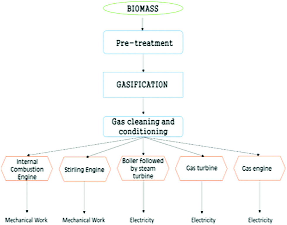 | ||
| Fig. 14 Flow chart of conventional multi-generation scheme employing biomass gasification. | ||
A potential solution to this drop in power output is to enhance the compression ratio (volume of the gas before compression to the volume post compression) from around 8 to 12 by increasing the H2 percentage in the inlet gas.287 This increase in compression ratio does raise the engine power but is limited by the increased potential for vibrations and knocking which are responsible for reduced engine life.209
6.2 Advanced concepts
000 hours of operation in a CHP context. This is notable since the gasifier is an updraft gasifier.289 Additionally, a 26 MWth plant in Denmark and a 15 MWth plant in Germany started in 2006 and 2012, respectively.290,291 Cogeneration units can provide heat and power to industrial, commercial and residential buildings. Co-generation of heat and power by biomass combustion is prevalent,292 albeit gasification is better in terms of electrical efficiency and the acceptable range of biomass qualities.89,285 However, many co-generation units for the production of thermal energy with electricity employing gas engines are installed and working successfully around the globe.89,285,290,291,293–298
Many researchers have investigated the co-generation strategy to enhance electricity production.42,290,291,299–313 Investigators have coupled a Rankine cycle with two gas engines, which additionally transforms 10–15% of heat into electricity, and improves biomass power efficiency from 25–30% to 40% or more.290,291 Another tactic to optimize the efficiency is to couple gas and steam turbines to generate power. This is commonly referred to as Integrated Gasification Combined Cycles (IGCC). This approach has a reported efficiency of 46% for coal gasification and power efficiency of around 32% for biomass gasification.307,308
This gasification technology can also support the enhancement of the amount of organic carbon in soil, which has an additional benefit of being a method of sequestering carbon. The term, ‘Bio-char’, has been coined to describe char which has been deliberately left un-gasified and is added to farm soil. Bio-char is known for recirculating organic carbon back into the ground and aiding in ionic adsorption, thus preventing leaching of vital nutrients and minerals into ground water.316 In addition, enhanced water holding capability results when bio-char is mixed with sandy soils.317–319 Although leaving some char un-gasified would decrease the efficiency of the BG process, it may provide a carbon-neutral alternative for fertilizer and bio-char production.
Some researchers have modelled H2 generation in conjunction with heat and power production.320–324 H2 production from rice husk in BG with O2 as the gasifying agent was studied theoretically.323 Investigators used two Rankine thermodynamic cycles during power generation for maximal heat retrieval with a H2 production efficiency of 40%. Electric power generation efficiency was 3.25% in the absence of CO2 compression for storage and 1.5% with compression. Poly-generation of H2, thermal energy and electricity was also modelled by investigators to evaluate H2 generation costs and process applicability in practical scenarios.320 Ten distinct processes were modelled employing different reactors for BG, and an exergy analysis was carried out for cases with and without thermal energy retrieval.321 Investigators also did thermo-economic modelling to inspect the repercussions of this new process to obtain H2, coupled with heat, electricity and CO2 sequestration. They found positive effects when combining different sub-systems to optimize thermal energy retrieval along with waste heat utilization.324
Apart from these theoretical investigations, large-scale experiments were also carried out under a project funded by the European Union to examine heat and power production with H2 generation.322 Unique gasifiers, as mentioned in the earlier section of this paper, were coupled with a secondary reactor for H2O gas shift reactions and a pressure swing adsorption unit to capture CO2. They report a H2 conversion efficiency of >66%.
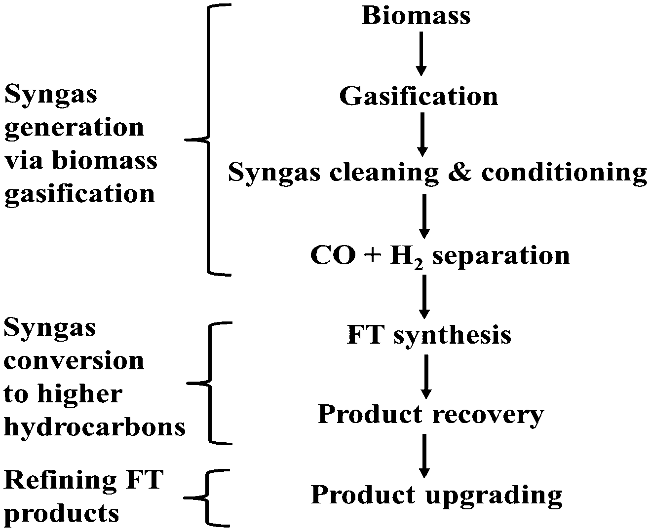 | ||
| Fig. 15 Flow chart depicting FT-fuel synthesis from biomass. | ||
Biomass gasification produces syngas which can act as a raw material for an FT process. If the fraction of H2 is low in syngas, then a water gas shift reactor is needed prior to FT synthesis. Syngas is converted to liquid fuels and/or chemicals via the FT process in the presence of Co-based or Fe-based catalysts. Co-based catalysts require higher H2 content in the syngas for fuel production. However, their productivity is more at higher conversion levels, than Fe-based catalysts.326
Climate change and fossil fuel depletion necessitate renewable transportation fuels. The gasifier-coupled FT plant concept presents an encouraging option in this regard. Investigations prove that FT fuels result in low emissions when employed in IC engines on account of the low volume of nitrogenous and aromatic species. Furthermore, these fuels do not contain sulphur which is considered as one of the major pollutants in IC engine exhaust gases.327 This process presents a promising alternative for the production of renewable liquid fuels. The FT process coupled with gasification is a feasible option to reduce the burden on conventional transportation fuel; however, it requires significant development and scale-up efforts for commercial-scale installations.
All methanation reactions (23)–(25) are exothermic in nature.9 Detailed methanation processes and clean-up techniques are mentioned in the literature.333–335
| 2CO + 2H2 → CH4 + CO2 −247 kJ mol−1 | (23) |
| CO + 3H2 → CH4 + H2O −206 kJ mol−1 | (24) |
| CO2 + 4H2 → CH4 + 2H2O −165 kJ mol−1 | (25) |
Liquid bio-fuels such as di-methyl ether (DME) or methanol are potential alternatives to oil-based conventional fuels such as gasoline or diesel on account of their suitable characteristics. Existing IC engine design, fuel filling station infrastructure and market acceptability coupled with low emissions make them a promising option over SNG or H2, though the main benefit of any liquid fuel is energy density and ready transportation. Benefits of multi-production of bio-fuels coupled with thermal energy and electricity production are similar to those for SNG multi-production.89 Researchers have investigated multi-production of heat, power and bio-fuels such as methanol, ethanol, methyl acetate, and FT diesel. They reported it to be cost-effective, more favorable and flexible than separate generation.336–339 However, it is less economical compared to fossil fuel generation when the oil price is low. This difference in economics could be mitigated by government-level subsidies or larger-scale generation benefits.94,340,341
Current state of commercialization of SNG. Throughout the last decade, many pilot plants have been installed to study the feasibility of SNG generation from syngas.334,342–344 Sweden is the first country to have a commercial unit to generate SNG from BG-produced syngas. The setup is located in Goteborg, with 20 MW capacity already installed out of a total of 100 MW. A 200 MW plant at Eon in Sweden was installed in March 2014 and is working successfully.345–347 A 1 MW plant was established in Gussing, Austria, to produce SNG from BG syngas, and is also working successfully.348 Thorough investigations undertaken by Wirth et al.344 demonstrated that in order for a Bio-SNG plant to be economical, the installed size should be equal to or greater than 20 MW (output basis). This value was based on the inclusion of intricate and costly processes such as gasification, gas cleaning and conditioning, catalytic methanation and carbon dioxide removal.
7. Mathematical modelling of gasification
Product gas characteristics and more general performance measures such as process economics and energy efficiency in BG depend on several parameters like the selection of a suitable gasifier as well as the choice and concentration of feedstock and other variables.189 Operating conditions such as pressure, temperature and flow inside the gasifier need to be optimized to achieve the desired performance. Evaluation of optimal conditions is frequently carried out through experiments which are quite costly and time consuming.9The solution to this problem is partially provided by mathematical modelling, where models can be generated to evaluate a variety of conditions quickly and cheaply. This simulation work saves time and resources and imparts qualitative data for real-life scenarios, albeit not as precisely as the experimentation work. Such models can be used to derive ideal conditions and permissible limits for gasifiers operating at elevated temperatures and pressures. Thus, they also enable the safety of the plant to be assessed before construction.349 It is also very helpful in testing various feedstocks and their behavior in different kinds of reactors without actually building them. Generally, the simulation of biomass gasification can be divided into 5 categories:
(i) Thermodynamic Equilibrium Models
(ii) Kinetic Models
(iii) Computational Fluid Dynamics Models (CFD)
(iv) Artificial Neural Network Models (ANN)
(v) Tar Models
Thermodynamic models aid in deriving outlet gas characteristics for a specific set of conditions employing a specific gasifier. While generating a thermodynamic model, it is assumed that reacting species are left for an infinite amount of time.31 It reveals the thermodynamic boundaries which exist for the given set of parametric conditions. Practically, it has been found that while the results reflect the system potential, they can vary considerably from real-life scenarios, thus necessitating a more accurate approach.
Kinetic modelling partially transcends this limitation. It considers the kinetics of key reactions which occur inside the gasifier during biomass gasification, along with gasifier hydrodynamics.350 It takes into account the process of biomass gasification for a fixed time and determinate volume, thus, making it more exact than the previous modelling method. The disadvantage is that although great strides have been made in the last few decades, the kinetic pathways and reaction rate constants are still not perfectly understood.
CFD includes a variety of processes such as heat and mass transfer, flow transfer, temperature dissemination, and gas yield, etc., by employing the solutions of numerous mathematical equations.351 It is highly useful and can be quite accurate, though is complex.
ANN is a comparatively new approach which is analogous to machine learning. When data from experiments are fed to the model, it produces numerical results, learning by itself.352 Its drawbacks include the lack of analytical results and failure in the cases of limited data.
7.1 Thermodynamic modelling
Application of the first and second laws to reacting systems, together with species mass balances result in equilibrium models, where the concentrations of reacting species minimize Gibbs free energy. Researchers have employed thermodynamic models to study gasification in BG.353–359 Antonopoulos et al.353 examined the impact of temperature inside the reactor and H2O content in the biomass (olive wood, miscanthus, and cardoon). They found that the reactor temperature was directly related to CO yield and inversely related to H2 and CO2 fractions in gas. In addition, they observed that the lower heating value of the outlet gas was indirectly related to the reactor temperature. More H2O in the inlet was responsible for less net energy in the fuel, as additional energy was required to vaporize the H2O. Their simulation results were very close to the experimental data, reflecting the significance of thermodynamic modelling.The impact of process variables, namely pressure, temperature and feedstock moisture, while employing agricultural wastes as biomass feedstock, were studied for biomass gasification by developing an equilibrium model.354 CH4 percentage was found to be a function of increasing pressure inside the reactor. However, this model was not very accurate and miscalculated the H2 and CH4 yield. Babu et al.355 employed the reactivity of char in the reduction zone as the basis to construct an equilibrium model for a BG. They studied steady state configuration and temperature contours over the entire length of the reduction area of the reactor. They validated the modelling results with experiments and reported that the char reactivity factor changed exponentially through the length of reduction zone in a BG. This research suggested the incorporation of an exponentially-varying char reactivity factor when constructing thermodynamic models to obtain more precise predictions.
Sandeep and Dasappa360 investigated air and oxy-steam biomass gasification based on the first and second law of thermodynamics. The model was generated for oxy-steam gasification in an open-top fixed bed downdraft gasifier with variable ER and S/B. At S/B of 0.75 (molar basis), maximum exergy efficiency obtained was 85% with energy efficiency of 82%. Drops in these efficiencies were found on increasing S/B on account of enthalpy loss in steam generation coupled with physical exergy loss of steam (in the product gas). Furthermore, decreases in efficiencies were observed for air gasification due to the presence of N2. A carbon boundary point was observed at S/B of 1.5 and ER of 0.23. This study demonstrated that higher S/B is needed for high H2 yield while lower S/B ensures an efficient process with high energy syngas.
Rokni and co-authors361 developed an equilibrium model for MSW gasification coupled with a solid oxide fuel cell (SOFC), which was combined with a Stirling engine to recover thermal energy of the off gases from SOFC cycles. The SOFC basically acted as a topping cycle for a Stirling engine. The whole system capacity was 120 kW, which acted as a de-centralized CHP plant. Equilibrium modelling was performed employing a 2-stage air-blown (autothermal) fixed bed reactor, using the Gibbs free energy minimization approach. The plant electrical efficiency varied from 43 to 48% as a function of MSW composition and plant design. The maximum plant efficiency was found to be 48% and CHP efficiency as 95%, at SOFC operating temperature of 690 °C, provided there was an unaltered fuel mass flow rate.
Vakalis et al.362 devised a novel approach called ‘Multi-box’ for thermodynamic modelling where they divided the whole reactor into multiple zones or boxes vis-à-vis gasification stages. They evaluated solid–vapour equilibria in small-scale downdraft gasifiers. Gases and char compositions were obtained for different ERs (0.2–0.3) and the results were compared with conventional modelling approach results. CO, H2, CO2, CH4 and char yields were closer to the real case scenario than what was found via conventional single-stage equilibrium modelling, reflecting the efficiency and accuracy of the technique.
Researchers have also applied thermodynamic models to study the influence of numerous parameters in the gas composition and yield when gasifying with a FBG363–369 and the unique gasifier.90,321,370–372 It is relatively easy to develop a thermodynamic model to forecast exit gas properties along with the maximum thermal efficiency. This approach can be made more accurate by utilizing empirical correlations deduced from experimental data.
The previously mentioned restrictions of equilibrium models can be alleviated by using kinetic modelling for gasification.373
7.2 Kinetic modelling
Kinetic modelling considers reaction kinetics and hydrodynamics of the gasifier and is thus potentially more accurate in deducing exit gas yield and composition.350,374 Unlike thermodynamic models, kinetic models can be applied to low-temperature gasification. Although it is more intricate than equilibrium models and its intricacy increases with the complexity of gasifier design, it is a more precise mathematical approach. The Arrhenius eqn (26) reflects the kinetic parameters which are significant to the model. It also quantifies the dependency on temperature.9 The laws of conservation of energy, mass and momentum are also included in the model.| k = Aexp(−Ea/RT) | (26) |
Researchers have developed kinetic models to study the parametric impact of various process variables on the gas composition and yield, using different feedstocks in different types of gasifiers.375–378 The reaction temperature and S/B were taken as parameters and a kinetic model was constructed by Inayat et al.376 using oil palm empty fruit bunch as the feedstock with steam as the gasifying media, coupled with in situ CO2 capture by CaO. The H2 produced was directly proportional to both reaction temperature and S/B. However, the efficiency was reported to drop when increasing S/B beyond a point. In addition, this model also deduced that temperature was a more important process variable than S/B. A kinetic model was developed to study temperature and species concentration profiles in both steady and dynamic states using biochar as a feedstock in a downdraft solar packed bed gasifier.375 It was found that a downdraft gasifier coupled with solar power was a feasible design. H2-rich exit gas was generated from the concept with an efficiency of 55%. These predictions were in accordance with the experimental measurements.
Sreejith and co-authors379 generated a kinetic model employing air-steam as the gasifying medium and wood as the feedstock in a fluidized bed gasifier, to study the influence of CaO as sorbent for in situ CO2 capture. The lower heating value of the syngas was enhanced from 5.58 to 6.12 MJ Nm−3 when the sorbent-to-biomass ratio was increased from 0.75 to 1.5, at ER of 0.25 and S/B of 1. Moreover, they reported an increase of 14 to 16% in H2 yield when sorbent was introduced in the system. The maximum H2 yield was 53% in the syngas at ER of 0.25, S/B of 1.5, sorbent-to-biomass ratio of 2.7 and temperature of 727 °C. Furthermore, they proved that from an energy efficiency point of view, air-steam gasification is better than steam gasification.
Khonde et al.380 developed a single reaction model (SRM) and a distributed activation energy model (DAEM) for rice husk gasification in a 2-stage BG with variable temperatures (700–900 °C) and residence times (12–48 s). They correlated the experimental data and investigated the kinetics of individual gases and tar cracking. Increase in temperature and residence time resulted in H2 rich syngas and maximum tar conversion of 91% was observed. They argued that N2 and air are more influential for secondary gaseous products. In addition, they asserted that the DAEM is more appropriate than the SRM on account of its accuracy in correlating tar conversion activity over a diverse range of conditions.
The use of computational software packages (Mathematica, MATLAB, ASPEN PLUS, are examples of such) can be incredibly useful at saving time, money and resources when applied correctly. Models have previously been applied to predict potential issues with designs and have been utilized to test novel ideas before the purchasing of capital equipment.9
7.3 Computational fluid dynamics modelling
CFD has emerged as a powerful and vital tool in modelling thermochemical reactors such as gasifiers. It is effective in deriving the optimum operating conditions and geometry, heat and mass transfer along with the gas yield to a reasonably good degree of accuracy, especially in FBGs, provided the reactor hydrodynamics are known.381 CFD models for BG necessitate sub-modelling of various stages such as vaporization, pyrolysis, char oxidation, etc., making it the most complicated modelling approach amongst the three discussed so far.382Some researchers have constructed CFD models to study different types of gasifiers taking diverse parameters.97,357,383 The cold gas efficiency, gas composition, conversion efficiency and temperature profile of a BG were investigated using wood as feedstock with the finite volume approach.383 Numerical simulation was performed on a high-resolution mesh which considered both solid and gaseous phases. Temperature profiles were deduced and matched with the experimental data along with the species density. The average temperature profile derived from the CFD model was higher than the experimental value while cold gas efficiency was lower than the ideal case. This variation was due to inability to capture the fine details of the highly complex phenomena taking place inside the gasifier. However, other gasifiers such as EFG, which have higher temperatures and less intricate gas–solid flow profiles can be modelled with greater precision.
Coute and co-authors384 developed a 2D CFD model based on the Eulerian–Eulerian approach to study the influence of O2 rich air on BG employing coffee husks as feedstock. The kinetic theory of granular flow was used to analyze the characteristics of dispersed phase and gas phase behaviors. The impact of O2 on operating temperature, S/B and syngas composition was also evaluated. It was reported that N2 and H2 molar fractions were enhanced with increasing O2 content while CO2 decreased. In addition, cold gas efficiency increased with increasing O2 whereas it decreased with S/B. This study was found to be in good agreement with the experimental results.
Savuto et al.385 generated a CFD code to evaluate the behavior of catalytic filters situated inside the freeboard of the reactor and to analyze their performance in steam reforming of CH4 and tar species. Parameters such as filtration velocity (70–110 m h−1) and temperature (750–850 °C) were investigated, which have impact on the filters' performance. It was observed that CH4 and C7H8 conversion doubled whereas C6H6 and C10H8 conversion were quadrupled, with a 100 °C rise in temperature. Furthermore, maximum conversion for tar and CH4 was reported at maximum temperature (850 °C) and minimum filtration velocity (70 m h−1). At these conditions, CH4 conversion was 33% while C6H6, C7H8 and C10H8 conversions were 41%, 75% and 85% respectively.
The latest advancements in CFD modelling have paved new ways for the optimization of biomass gasification coupled with reactor design.351 The capability of CFD to infer gasifier performance under a broad range of process variables makes it a highly promising option.
7.4 Artificial neural network modelling
ANN is a relatively fresh approach for the modelling of complex processes. It is a tool which is already in use in different areas such as signal processing but its application in outcome predictions in BG is quite new. A significant advantage of ANNs is that they do not require the formulation of complex mathematical equations and they can learn and identify non-linear relations themselves.386 Thus, ANNs may be an interesting option to evaluate BG where complex non-linearities occur in the data-set.Very few researchers have modelled biomass gasification using the ANN approach.352,387 A model was constructed to derive exit gas characteristics and heat content along with the temperature profile in a FBG.387 Predictions were very close to the experimental data. At a S/B of 2.53, the highest H2 yield was reported to be 29.1% in experiments. The ANN predicted this value as 28.2%, reflecting the potential of ANN models to simulate complex gasification to significant precision.
Mikulandric et al.388 developed advanced control solutions centred on a ‘feedforward-feedback’ control strategy employing collected operational data from a 75 MWth fixed bed gasification plant operated by Technical University, Dresden. The influence of the control approach was evaluated by employing an ANN-based prediction model. It was reported that the introduction of advanced control systems for numerous process variables can increase process efficiency by 25% on account of alterations in air and fuel distribution on partial product gas generation loads. Furthermore, this approach decreased the adverse environmental effects of BG systems. This work demonstrates the significance of advanced modelling strategies such as ANN for optimizing gasification process.
ANN modelling is seen as an encouraging approach especially for UG and dual FBG which are difficult to model by other methods; however, it requires large amounts of data in different regions of the operating space to produce a sufficiently large database for ANN training and model development.
7.5 Tar formation and destruction models
Tar models are classified as either single-compound models, lumped models or kinetic models.184 Single-compound models represent simple versions of biomass and they reflect how this biomass would react whereas lumped and kinetic models utilize heat and mass transfer information along with rate of reactions. Font-Palma et al.184 reported, via comprehensive experimental investigations, acetol, acetic acid and guaiacols as primary tar model compounds, phenols, cresols and toluene as secondary tar model compounds and naphthalene as tertiary tar species. Zhao et al.389,390 studied toluene and Ji et al.389,390 investigated phenol with a single-compound model and developed a thermodynamic model for tar formation. Benzene and naphthalene were the only HCs produced when toluene was chosen as the tar model and in the latter case, phenol cracking generated naphthalene and benzene followed by their decomposition to non-condensable gases and H2O. These simulation results are in close agreement with the experimental work done and, therefore, demonstrate the applicability of tar model compounds when attempting to understand tar destruction while minimizing time-consuming and expensive experiments.To facilitate the simulation of bubbling FBG, many researchers356,391–395 conducted tar modelling using a lumped-model approach, while Abdelouahed et al.396 developed lumped models for dual FBG. Their simulation results were in agreement with the experimental investigations. Detailed kinetic models can be studied in the work done by many investigators.397–401 The single compound model approach using stable compounds like toluene, benzene and naphthalene or the lumped-model approach are considered the best for tar modelling, although these compounds appear as secondary and tertiary tars with no knowledge of kinetics of their development. Comprehensive kinetic models employ numerous species and, therefore, are considered to be very complex when simulating biomass inside a gasifier. A more feasible approach is to keep to a minimum the number of tar species while modelling tar development during gasification.184 Detailed work can be found in the literature.184,266,356,389–395,397–403
8. Socio-environmental analysis
The major motivation behind biomass gasification is to exploit a large variety of waste materials as feedstock, to increase resource efficiency and reduce adverse climate change via CO2 mitigation. Although gasification is a key technology to utilize biomass waste, it poses many potential kinds of risks which have a significant impact on society and the environment at large.404 One of the main problems is the potential emissions of particulates (PM10 or PM2.5, dioxins, PAH), CO, SOx, NOx and volatile organics.405 These pollutants can interact with humans through inhalation, ingestion and dermal contact and thus pose a grave threat to human health.406 A detailed analysis has been depicted in Table 9.| Type of pollutant | Feature | Effect on respiratory system | Effect on cardio-vascular system | Effect on nervous system | Effect on digestive system | Congenital problems |
|---|---|---|---|---|---|---|
| Particulates | Size <2.5 μm is harmful; toxicity varies depending upon chemical composition; PAH, dioxins, Pb, Hg are considered toxic | Nose and throat irritation, COPD, asthma, lung cancer | Myocardial infraction | Headache, fatigue | Liver cell damage, liver cancer, gastro-intestinal cancer | Reduced fetal growth, preterm birth, low birth weight, motor and cognitive disabilities |
| CO | Incomplete combustion produces CO; atmospheric half-life of 1–2 months | Asthma, COPD, bronchitis, dyspoenia | Lung inflammation, angina infraction, cardiac arrest | Schizophrenia | — | Preterm birth, cardiac defects |
| SOx | Oxides of sulphur; atmospheric life span is 4–10 days | Nose and throat irritation, asthma | — | — | — | Preterm birth |
| NOx | Oxides of nitrogen; life span of 1–2 weeks | Bronchitis, COPD, asthma, lung cancer | Cardiac mortality and morbidity | Sleep disorders, fatigue | — | Reduced fetal growth, preterm birth |
| Volatile organics | Large range of chemicals which are easily evaporated at room temperature; examples – benzene, toluene, etc. | Asthma | Lung inflammation | Nausea, dizziness | Liver failure, kidney failure | Preterm birth, motor and cognitive disabilities |
On the other hand, biomass combustion can also emit complex mixtures of particles (PM2.5), semi-volatile matter and gases. Particulate organic matter in PM2.5 ranges from alkanes, aromatic compounds to carboxylic acids. These have soluble organic emissions with high concentration of organic tracers (from lignin and cellulose combustion).410–412 These pollutants are carcinogenic in nature and can induce potentially fatal tumors. Their rates of discharge are very high when compared to efficient biomass gasification. Therefore, as far as harmful emissions are concerned, biomass gasification and even fossil fuel combustion are generally better than biomass combustion if the latter does not have pollution mitigation, especially SOx and NOx.412 Consequently, gasification is preferred for biomass utilization on account of very low emissions after an efficient gas clean-up and conditioning unit.
Gasification is a system which has an inherent risk for fire and explosion vulnerability, especially since the gasifiers operate at high temperature and pressure.413 This probability enhances significantly when H2 is the desired product. It is highly flammable and, therefore, necessitates a great amount of caution. Ash and tars are noteworthy elements which have potential for environmental contamination. The waste streams formed require a suitable disposal system to be implemented that meets all legislative guidelines. Techniques like low-temperature CFB which can produce ash with negligible PAH impurity pose little threat to the environment, meaning that this ash can also be used as a fertilizer.414
The idea of gasifying biomass resources in remote or sparsely populated areas to provide heat and electricity is one that has received substantial attention over many years, albeit the progress has been slow.4,415,416 Currently, there are major rural gasification programs in countries as diverse as China such as crop straw-based projects like the Xiaoliujia project, projects in Jincheng City and elsewhere;417 India has also seen deployment in places such a Karnataka, where two 500 kW gasifers have been built, along with Africa and elsewhere.418,419
One of the successful projects employing a decentralized biomass gasification-based power generation system in an un-electrified Indian village called Hosahalli village in Karnataka province emphatically reflects the promising nature of gasification systems.420 Power derived from a biomass gasification system was employed for lighting, drinking water supply via pipes, irrigation water supply and flour milling. A 20 kW gasifier-engine generator system with all the accessories for fuel processing and electricity distribution was installed in 1988 and operated until 2004. It met all the electricity needs of the entire village. Cost of fuel and, operation and maintenance costs were calculated as INR 5.85 per kW h at a load of 5 kW and INR 3.34 per kW h at a load of 20 kW. The Hosahalli project has proved the technical and operating viability of biomass gasification systems in rural areas of developing countries. Among all the renewable energy power generation technologies, decentralized power generation via biomass gasification offers great potential for meeting rural energy needs on account of its technological maturity, availability in different capacity scales, feasibility of operation during different times of day/year, economic feasibility, biodiversity preservation and aid in climate change mitigation.
Often the goal of using biomass as an energy source is simply to replace the cook stove in small communities with a reliable and relatively clean source of heating.421,422 This is especially attractive if the biomass can replace polluting fuels like coal briquettes, and is also interesting given the very large amounts of such material available in some locations (e.g. for India resources are estimated as 120–150 million metric tonnes per annum which represents a potential of about 18000 MW energy).422 Such units are usually small, typically no more than 10 to 200 hundred kWth and are expected to be robust non-polluting devices, which can be operated in a communal setting with diverse feedstock ranging from straws to materials like coconut shells.423 Such systems can also be combined with economic stimulus packages such as soft loans to rural communities to pay for the capital cost of such systems and to provide start-up funding to operate such systems in conjunction with NGOs or other organizations.4 In some circumstances small gasifiers have proven to be more economic for electricity generation than for instance importing diesel fuels to remote communities424 and gasification technology is being seen as a vital method for dealing with energy poverty.425,426 Such technologies also offer the possibility of avoiding pollution associated with the disposal of agricultural wastes,427 although it has been noted that to date there has been relatively little testing of such technologies in real settings, and this is essential if gasification technologies are to fully displace conventional systems in rural locations.
Researchers including Luque et al.208 and Demirbas et al.210 have conducted extensive investigations on diverse aspects of biofuels. Synthetic biofuels like Bio-DME, Bio-H2, hydrothermal upgraded (HTU) diesel, and linear chain HCs, etc., are prepared from gasification product gases by employing different processes. In the absence of contaminants such as particulates, tar and other toxic gases, they are considered cleaner. With a high cetane value, they can be used in IC engines (except Bio-DME) with advantages such as clean combustion, albeit with a requirement for engine modification.208 Production of bio-ethanol is also an interesting idea to help curb crude oil usage and environmental pollution. However, the technologies available for the majority of these biofuels are in their infancies with respect to production, storage and transportation. Moreover, production of these fuels is a costly affair on account of high installation and production costs.208,210
Biofuels have some other adverse environmental effects which should also be considered in their long-term sustainability assessment. Direct GHG emissions such as from fertilizer usage and indirect from land use change, coupled with the adverse impact on biodiversity forms the main threat to wide-scale deployment of biomass growth for biofuel generation.428,429 Soil preservation issues and water utilization are other factors that militate against the use of biofuels.430,431 The main concerns related to societal impact should be land use change and fiscal sustainability along with proper administrative guidelines. On the other hand, the independent production of biofuel directly improves a country's energy security and their current and expected future energy mix. Biomass gasification also provides an opportunity to provide additional jobs in R&D, engineering and procurement.
9. Conclusions
Biomass is a significant non-conventional energy reserve. Its topographical independence and comparatively ample availability makes it a promising choice over other renewable sources such as solar, wind or hydroelectric storage. Bioenergy technologies such as gasification can utilize a variety of biomass types to produce useful products including electrical power and hydrogen. A deep understanding and knowledge of the process along with the alternative approaches to gasification are required for optimization and advancements in a cost-effective manner.An in-depth survey throughout this paper has provided evidence about various biomass feedstocks and the applications of the potential gasification products. The impacts of different parameters on the properties and yields of the individual products have been discussed with the aim to aid optimization of future research and the process as a whole. Unique gasifier designs, including large-scale multi-stage gasification and smaller decentralized pyrolysis plants near the biomass source coupled with a centralized gasification unit are interesting and potentially economical ways to optimize biomass utilization. More novel technologies, such as plasma gasification and SCWG could be effective ways to make the most of toxic and wet biomass to generate power. Various poly-generation approaches to produce heat and power along with other products like syngas, H2, fertilizer or biochar demonstrate the developments and opportunities in gasification.
Understanding of tar formation, and advancements in modelling have been mentioned to pave the way for future expansion in discovering and designing new catalysts, to make the gasification process cleaner and operate with a higher efficiency. Conventional modelling is being supplemented and in some cases replaced by CFD and ANN. Although gasification has some adverse social and environmental impacts, they can be minimized through appropriate technological and policy implementations.
This paper presents a positive case for biomass gasification as a promising, viable and economically beneficial technology. It has been shown that the process is not limited to a particular feedstock and specific product, but is flexible towards the treatment of biomass wastes that may be toxic or contaminated, for the generation of diversified usable products.
Acknowledgements
M. Zhao thanks for the support by the National Recruitment Program of Global Youth Experts (The National Youth 1000 – Talent Program) of China (grant number: 20151710227); M. Zhao, V. S. Sikarwar and M. Z. Memon are grateful for the funding support by Tsinghua University Initiative Scientific Research Program (grant number: 20161080094) and the Volvo Group in a research project of the Research Center for Green Economy and Sustainable Development, Tsinghua University (grant number: 20153000181). P. Clough thanks the EPSRC for funding a DTA studentship and J. Yao thanks Imperial College for funding a studentship. We also thank Ms Shujuan Zhang for her assistance.References
- R. Saidur, E. A. Abdelaziz, A. Demirbas, M. S. Hossain and S. Mekhilef, Renewable Sustainable Energy Rev., 2011, 15, 2262–2289 CrossRef CAS.
- International Energy Agency Energy Database, http://www.worldenergyoutlook.org/resources/energydevelopment/energyaccessdatabase/, accessed November 2015.
- S. Heidenreich and P. U. Foscolo, Prog. Energy Combust. Sci., 2015, 46, 72–95 CrossRef.
- B. Buragohain, P. Mahanta and V. S. Moholkar, Renewable Sustainable Energy Rev., 2010, 14, 73–92 CrossRef CAS.
- Ministry of Coal, Government of India, http://coal.nic.in/content/coal-reserves, accessed September 2014.
- National Energy Technology Laboratory, USA, http://www.netl.doe.gov/File%20Library/Research/Coal/energy%20systems/gasification/gasifipedia/index.html, accessed March 2016.
- A. K. Rajvanshi, Alternative energy in agriculture, 1986, 2, 82–102 Search PubMed.
- National Energy Technology Laboratory USA, http://www.netl.doe.gov/research/coal/energy-systems/gasification/gasifipedia/wabash/, accessed September 2000.
- P. Basu, Biomass Gasification and Pyrolysis, Elsevier, Oxford, 2010 Search PubMed.
- J. P. Ciferno and J. J. Marano, presented in part at US Department of Energy, National Energy Technology Laboratory, June 2002.
- G. Foley and G. Barnard, Biomass gasification in developing countries-Technical Report, International Institute for Environment and Development, Earthscan, UK, 1983 Search PubMed.
- H. Knoef and J. Ahrenfeldt, Handbook biomass gasification, BTG biomass technology group, The Netherlands, 2005 Search PubMed.
- S. Rapagnà, N. Jand, A. Kiennemann and P. U. Foscolo, Biomass Bioenergy, 2000, 19, 187–197 CrossRef.
- C. Higman and M. v. d. Burgt, Gasification, Gulf Professional Publishing, Elsevier, USA, 2008 Search PubMed.
- P. Parthasarathy and K. S. Narayanan, Renewable Energy, 2014, 66, 570–579 CrossRef CAS.
- P. McKendry, Bioresour. Technol., 2002, 83, 37–46 CrossRef CAS PubMed.
- P. Basu, in Biomass Gasification and Pyrolysis, ed. P. Basu, Academic Press, Boston, 2010, pp. 97–116 Search PubMed.
- C. Li and K. Suzuki, Renewable Sustainable Energy Rev., 2009, 13, 594–604 CrossRef CAS.
- A. George, A. Brandt, K. Tran, S. M. N. S. Zahari, D. Klein-Marcuschamer, N. Sun, N. Sathitsuksanoh, J. Shi, V. Stavila and R. Parthasarathi, Green Chem., 2015, 17, 1728–1734 RSC.
- R. El Hage, N. Brosse, L. Chrusciel, C. Sanchez, P. Sannigrahi and A. Ragauskas, Polym. Degrad. Stab., 2009, 94, 1632–1638 CrossRef CAS.
- H. L. Chum and R. P. Overend, Fuel Process. Technol., 2001, 71, 187–195 CrossRef CAS.
- K. J. Ptasinski, Biofuels, Bioprod. Biorefin., 2008, 2, 239–253 CrossRef CAS.
- P. H. Hasler and T. Nussbaumer, Biomass Bioenergy, 1999, 16.6, 385–395 CrossRef.
- Combustion Gasification and Propulsion Laboratory, IISc, India, http://cgpl.iisc.ernet.in/site/Portals/0/Technologies/Gasification%20Technology.pdf, accessed August 2011.
- S. Dasappa, P. Paul, H. Mukunda, N. Rajan, G. Sridhar and H. Sridhar, Curr. Sci., 2004, 87, 908–916 CAS.
- P. Giaordano and S. Dasappa, Test of different biomass into the IISc open top co-current gasifier, Swiss Federale Office of Energy, Project 39772 Contract 80847, 2001.
- H. S. Mukunda, S. Dasappa, P. J. Paul, N. K. S. Rajan and U. Shrinivasa, Energy Sustainable Dev., 1994, 1, 27–38 CrossRef.
- P. Basu, Biomass Gasification and Pyrolysis, Academic Press, Boston, 2010, pp. 167–228 Search PubMed.
- K. Gallucci, P. U. Foscolo, presented in part at 16th European Biomass Conference and Exhibition, Valencia, Spain, May 2008.
- G. Galeno, M. Minutillo and A. Perna, Int. J. Hydrogen Energy, 2011, 36, 1692–1701 CrossRef CAS.
- P. Basu, Biomass Gasification and Pyrolysis, Academic Press, Boston, 2010, pp. 117–165 Search PubMed.
- D. L. Klass, Biomass for renewable energy, fuels, and chemicals, Academic press, USA, 1998 Search PubMed.
- G. Tomlinson, D. Gray, M. Berger, Produced by MITRE Corporation for National Renew. Energ. Laboratory, USA, under contract number AL-4159, 1996.
- P. J. Woolcock and R. C. Brown, Biomass Bioenergy, 2013, 52, 54–84 CrossRef CAS.
- A. Demirbaş, Energy Convers. Manage., 2002, 43, 897–909 CrossRef.
- H. De Lasa, E. Salaices, J. Mazumder and R. Lucky, Chem. Rev., 2011, 111, 5404–5433 CrossRef CAS PubMed.
- N. Nipattummakul, I. I. Ahmed, A. K. Gupta and S. Kerdsuwan, Int. J. Hydrogen Energy, 2011, 36, 3835–3843 CrossRef CAS.
- I. Dincer, Int. J. Hydrogen Energy, 2012, 37, 1954–1971 CrossRef CAS.
- C. Franco, F. Pinto, I. Gulyurtlu and I. Cabrita, Fuel, 2003, 82, 835–842 CrossRef CAS.
- N. Nipattummakul, S. Pathumsawad and S. Kerdsuwan, International Conference on Thermal Treatment Technologies and Hazardous Waste Combustors, California, USA, May 2010.
- L. Wei, S. Xu, L. Zhang, C. Liu, H. Zhu and S. Liu, Int. J. Hydrogen Energy, 2007, 32, 24–31 CrossRef CAS.
- P. V. Aravind and W. De Jong, Prog. Energy Combust. Sci., 2012, 38, 737–764 CrossRef CAS.
- M. Asadullah, Renewable Sustainable Energy Rev., 2014, 29, 201–215 CrossRef CAS.
- D. J. Wilhelm, D. R. Simbeck, A. D. Karp and R. L. Dickenson, Fuel Process. Technol., 2001, 71, 139–148 CrossRef CAS.
- I. Wender, Fuel Process. Technol., 1996, 48, 189–297 CrossRef CAS.
- N. Abdoulmoumine, A. Kulkarni and S. Adhikari, Ind. Eng. Chem. Res., 2014, 53, 5767–5777 CrossRef CAS.
- H. Cui, S. Q. Turn, V. Keffer, D. Evans, T. Tran and M. Foley, Energy Fuels, 2010, 24, 1222–1233 CrossRef CAS.
- S. Hurley, C. C. Xu, F. Preto, Y. Shao, H. Li, J. Wang and G. Tourigny, Fuel, 2012, 91, 170–176 CrossRef CAS.
- Y. Ohtsuka, N. Tsubouchi, T. Kikuchi and H. Hashimoto, Powder Technol., 2009, 190, 340–347 CrossRef CAS.
- L. A. Bissett, An engineering assessment of entrainment gasification, U.S. Department of Energy, MERC/RI-78/2, Morgantown, USA, 1978.
- F. Fabry, C. Rehmet, V. Rohani and L. Fulcheri, Waste Biomass Valorization, 2013, 4, 421–439 CrossRef CAS.
- N. Agon, M. Hrabovský, O. Chumak, M. Hlína, V. Kopecký, A. Ma
![[s with combining breve]](https://www.rsc.org/images/entities/char_0073_0306.gif) láni, A. Bosmans, L. Helsen, S. Skoblja and G. Van Oost, Waste Manage., 2016, 47, 246–255 CrossRef CAS PubMed.
láni, A. Bosmans, L. Helsen, S. Skoblja and G. Van Oost, Waste Manage., 2016, 47, 246–255 CrossRef CAS PubMed. - I. Matveev, Plasma Assisted Combustion, and Pollution Control, Methods of Plasma Generation for PAC, Publishers Outside Press Inc., Denver, 2016, vol. 1 Search PubMed.
- I. Matveev, Plasma Assisted Combustion, and Pollution Control, Methods of Plasma Generation for PAC, Publishers Outside Press Inc., Denver, 2016, vol. 2 Search PubMed.
- K. A. Magrini-Bair, S. Czernik, R. French, Y. O. Parent, E. Chornet, D. C. Dayton, C. Feik and R. Bain, Appl. Catal., A, 2007, 318, 199–206 CrossRef CAS.
- C. Pfeifer, R. Rauch and H. Hofbauer, Ind. Eng. Chem. Res., 2004, 43, 1634–1640 CrossRef CAS.
- J. Delgado, M. P. Aznar and J. Corella, Ind. Eng. Chem. Res., 1997, 36, 1535–1543 CrossRef CAS.
- A. Olivares, M. P. Aznar, M. A. Caballero, J. Gil, E. Francés and J. Corella, Ind. Eng. Chem. Res., 1997, 36, 5220–5226 CrossRef CAS.
- A. Orío, J. Corella and I. Narváez, Ind. Eng. Chem. Res., 1997, 36, 3800–3808 CrossRef.
- S. Rapagnà, N. Jand and P. U. Foscolo, Int. J. Hydrogen Energy, 1998, 23, 551–557 CrossRef.
- P. A. Simell, E. K. Hirvensalo, V. T. Smolander and A. O. I. Krause, Ind. Eng. Chem. Res., 1999, 38, 1250–1257 CrossRef CAS.
- J. Corella, J. M. Toledo and R. Padilla, Energy Fuels, 2004, 18, 713–720 CrossRef CAS.
- L. Devi, K. J. Ptasinski, F. J. J. G. Janssen, S. V. B. Van Paasen, P. C. A. Bergman and J. H. A. Kiel, Renewable Energy, 2005, 30, 565–587 CrossRef CAS.
- R. L. Bain, D. C. Dayton, D. L. Carpenter, S. R. Czernik, C. J. Feik, R. J. French, K. A. Magrini-Bair and S. D. Phillips, Ind. Eng. Chem. Res., 2005, 44, 7945–7956 CrossRef CAS.
- D. Świerczyński, C. Courson, L. Bedel, A. Kiennemann and J. Guille, Chem. Mater., 2006, 18, 4025–4032 CrossRef.
- D. Swierczynski, C. Courson and A. Kiennemann, Chem. Eng. Process., 2008, 47, 508–513 CrossRef CAS.
- H. O. A. Fredriksson, R. J. Lancee, P. C. Thüne, H. J. Veringa and J. W. H. Niemantsverdriet, Appl. Catal., B, 2013, 130–131, 168–177 CrossRef CAS.
- M. Virginie, J. Adánez, C. Courson, L. F. De Diego, F. García-Labiano, D. Niznansky, A. Kiennemann, P. Gayán and A. Abad, Appl. Catal., B, 2012, 121–122, 214–222 CrossRef CAS.
- S. Rapagnà, K. Gallucci, M. Di Marcello, P. U. Foscolo, M. Nacken, S. Heidenreich and M. Matt, Fuel, 2012, 97, 718–724 CrossRef.
- M. Virginie, C. Courson, D. Niznansky, N. Chaoui and A. Kiennemann, Appl. Catal., B, 2010, 101, 90–100 CrossRef CAS.
- H. Depner and A. Jess, Fuel, 1999, 78, 1369–1377 CrossRef CAS.
- L. Ma, H. Verelst and G. V. Baron, Catal. Today, 2005, 105, 729–734 CrossRef CAS.
- M. Nacken, M. Lina, K. Engelen, S. Heidenreich and G. V. Baron, Ind. Eng. Chem. Res., 2007, 46, 1945–1951 CrossRef CAS.
- Y. Hu, M. Watanabe, C. Aida and M. Horio, Chem. Eng. Sci., 2006, 61, 1854–1863 CrossRef CAS.
- M. Stemmler, A. Tamburro and M. Müller, Fuel, 2013, 108, 31–36 CrossRef CAS.
- W. F. Elseviers and H. Verelst, Fuel, 1999, 78, 601–612 CrossRef CAS.
- V. Patrick, G. R. Gavalas, M. Flytzani-Stephanopoulos and K. Jothimurugesan, Ind. Eng. Chem. Res., 1989, 28, 931–940 CrossRef CAS.
- Y. Zeng, S. Kaytakoglu and D. P. Harrison, Chem. Eng. Sci., 2000, 55, 4893–4900 CrossRef CAS.
- M. Stemmler and M. Müller, Ind. Eng. Chem. Res., 2010, 49, 9230–9237 CrossRef CAS.
- M. Diaz-Somoano and M. R. Martínez-Tarazona, Energy Fuels, 2005, 19, 442–446 CrossRef CAS.
- K. J. Wolf, M. Müller, K. Hilpert and L. Singheiser, Energy Fuels, 2004, 18, 1841–1850 CrossRef CAS.
- D. Barisano, C. Freda, F. Nanna, E. Fanelli and A. Villone, Bioresour. Technol., 2012, 118, 187–194 CrossRef CAS PubMed.
- A. Gómez-Barea, P. Ollero and B. Leckner, Fuel, 2013, 103, 42–52 CrossRef.
- U. Henriksen, J. Ahrenfeldt, T. K. Jensen, B. Gøbel, J. D. Bentzen, C. Hindsgaul and L. H. Sørensen, Energy, 2006, 31, 1542–1553 CrossRef CAS.
- F. Trippe, M. Fröhling, F. Schultmann, R. Stahl and E. Henrich, Fuel Process. Technol., 2011, 92, 2169–2184 CrossRef CAS.
- S. Czemik and A. Bridgwater, Energy Fuels, 2004, 18, 590–598 CrossRef.
- A. Gómez-Barea, B. Leckner, A. Villanueva Perales, S. Nilsson and D. Fuentes Cano, Appl. Therm. Eng., 2013, 50, 1453–1462 CrossRef.
- P. Hofmann, A. Schweiger, L. Fryda, K. D. Panopoulos, U. Hohenwarter, J. D. Bentzen, J. P. Ouweltjes, J. Ahrenfeldt, U. Henriksen and E. Kakaras, J. Power Sources, 2007, 173, 357–366 CrossRef CAS.
- J. Ahrenfeldt, T. P. Thomsen, U. Henriksen and L. R. Clausen, Appl. Therm. Eng., 2013, 50, 1407–1417 CrossRef CAS.
- S. Nilsson, A. Gómez-Barea, D. Fuentes-Cano and P. Ollero, Fuel, 2012, 97, 730–740 CrossRef CAS.
- A. Gomez-Barea, S. Nilsson, F. V. Barrero and M. Campoy, Fuel Process. Technol., 2010, 91, 1624–1633 CrossRef CAS.
- S. Nilsson, A. Gómez-Barea and D. F. Cano, Fuel, 2012, 92, 346–353 CrossRef CAS.
- T. P. Thomsen, J. Ahrenfeldt and S. T. Thomsen, Biomass Bioenergy, 2013, 53, 81–94 CrossRef CAS.
- P. Haro, F. Trippe, R. Stahl and E. Henrich, Appl. Energy, 2013, 108, 54–65 CrossRef CAS.
- A. V. Bridgwater, Biomass Bioenergy, 2012, 38, 68–94 CrossRef CAS.
- http://www.bioliq.de, accessed February 2016.
- T. Jakobs, N. Djordjevic, S. Fleck, M. Mancini, R. Weber and T. Kolb, Appl. Energy, 2012, 93, 449–456 CrossRef CAS.
- H. Leibold, A. Hornung and H. Seifert, Powder Technol., 2008, 180, 265–270 CrossRef CAS.
- S. Heidenreich, Fuel, 2013, 104, 83–94 CrossRef CAS.
- Y. Somrang, PhD thesis, Imperial College London, 2012.
- A. Oasmaa and S. Czernik, Energy Fuels, 1999, 13, 914–921 CrossRef CAS.
- L. Tang, H. Huang, H. Hao and K. Zhao, J. Electrost., 2013, 71, 839–847 CrossRef.
- I. Janajreh, S. S. Raza and A. S. Valmundsson, Energy Convers. Manage., 2013, 65, 801–809 CrossRef CAS.
- L. Zhang, C. Xu and P. Champagne, Energy Convers. Manage., 2010, 51, 969–982 CrossRef CAS.
- Y. Kalinci, A. Hepbasli and I. Dincer, Int. J. Hydrogen Energy, 2011, 36, 11408–11417 CrossRef CAS.
- A. Mountouris, E. Voutsas and D. Tassios, Energy Convers. Manage., 2008, 49, 2264–2271 CrossRef CAS.
- P. Rutberg, A. N. Bratsev, V. A. Kuznetsov, V. E. Popov, A. A. Ufimtsev and S. V. Shtengel, Biomass Bioenergy, 2011, 35, 495–504 CrossRef CAS.
- J. L. Shie, F. J. Tsou and K. L. Lin, Bioresour. Technol., 2010, 101, 5571–5577 CrossRef CAS PubMed.
- L. Tang and H. Huang, Fuel, 2005, 84, 2055–2063 CrossRef CAS.
- M. Hlina, M. Hrabovsky, T. Kavka and M. Konrad, Waste Manage., 2014, 34, 63–66 CrossRef CAS PubMed.
- C. J. Lupa, S. R. Wylie, A. Shaw, A. Al-Shamma'A, A. J. Sweetman and B. M. J. Herbert, Fuel Process. Technol., 2012, 97, 79–84 CrossRef CAS.
- D. H. Shin, Y. C. Hong, S. J. Lee, Y. J. Kim, C. H. Cho, S. H. Ma, S. M. Chun, B. J. Lee and H. S. Uhm, Surf. Coat. Technol., 2013, 228, S520–S523 CrossRef CAS.
- S. J. Yoon and J. G. Lee, Int. J. Hydrogen Energy, 2012, 37, 17093–17100 CrossRef CAS.
- S. J. Yoon, Y. M. Yun, M. W. Seo, Y. K. Kim, H. W. Ra and J. G. Lee, Int. J. Hydrogen Energy, 2013, 38, 14559–14567 CrossRef CAS.
- Ottawa Citizen Online News, http://ottawacitizen.com/news/local-news/plasco-energy-group-files-for-creditor-protection, accessed February 2015.
- The Environment Media Group Ltd. News, http://www.letsrecycle.com/news/latest-news/words-largest-gasification-plant-nears-completion/, accessed May 2015.
- A. Kruse, Biofuels, Bioprod. Biorefin., 2008, 2, 415–437 CrossRef CAS.
- A. Kruse, J. Supercrit. Fluids, 2009, 47, 391–399 CrossRef CAS.
- Y. Matsumura, T. Minowa, B. Potic, S. R. A. Kersten, W. Prins, W. P. M. Van Swaaij, B. Van De Beld, D. C. Elliott, G. G. Neuenschwander, A. Kruse and M. J. Antal Jr, Biomass Bioenergy, 2005, 29, 269–292 CrossRef CAS.
- P. Basu, Biomass Gasification and Pyrolysis, Academic Press, Boston, 2010, pp. 229–267 Search PubMed.
- Y. Guo, S. Z. Wang, D. H. Xu, Y. M. Gong, H. H. Ma and X. Y. Tang, Renewable Sustainable Energy Rev., 2010, 14, 334–343 CrossRef CAS.
- A. J. Byrd, S. Kumar, L. Kong, H. Ramsurn and R. B. Gupta, Int. J. Hydrogen Energy, 2011, 36, 3426–3433 CrossRef CAS.
- Y. Chen, L. Guo, W. Cao, H. Jin, S. Guo and X. Zhang, Int. J. Hydrogen Energy, 2013, 38, 12991–12999 CrossRef CAS.
- E. Kipçak and M. Akgün, J. Supercrit. Fluids, 2012, 69, 57–63 CrossRef.
- A. Miller, D. Hendry, N. Wilkinson, C. Venkitasamy and W. Jacoby, Bioresour. Technol., 2012, 119, 41–47 CrossRef CAS PubMed.
- V. Sricharoenchaikul, Bioresour. Technol., 2009, 100, 638–643 CrossRef CAS PubMed.
- J. Yanik, S. Ebale, A. Kruse, M. Saglam and M. Yüksel, Fuel, 2007, 86, 2410–2415 CrossRef CAS.
- W. Feng, H. J. Van Der Kooi and J. De Swaan Arons, Chem. Eng. Process., 2004, 43, 1459–1467 CrossRef CAS.
- P. Azadi and R. Farnood, Int. J. Hydrogen Energy, 2011, 36, 9529–9541 CrossRef CAS.
- D. C. Elliott, Biofuels, Bioprod. Biorefin., 2008, 2, 254–265 CrossRef CAS.
- F. Marias, S. Letellier, P. Cezac and J. P. Serin, Biomass Bioenergy, 2011, 35, 59–73 CrossRef CAS.
- Y. Lu, L. Guo, X. Zhang and Q. Yan, Chem. Eng. J., 2007, 131, 233–244 CrossRef CAS.
- D. Castello and L. Fiori, Bioresour. Technol., 2011, 102, 7574–7582 CrossRef CAS PubMed.
- N. H. Florin and A. T. Harris, Chem. Eng. Sci., 2008, 63, 287–316 CrossRef CAS.
- P. McKendry, Bioresour. Technol., 2002, 83, 55–63 CrossRef CAS PubMed.
- L. Han, Q. Wang, Y. Yang, C. Yu, M. Fang and Z. Luo, Int. J. Hydrogen Energy, 2011, 36, 4820–4829 CrossRef CAS.
- D. Sutton, B. Kelleher and J. R. H. Ross, Fuel Process. Technol., 2001, 73, 155–173 CrossRef CAS.
- X. Xiao, D. D. Le, L. Li, X. Meng, J. Cao, K. Morishita and T. Takarada, Biomass Bioenergy, 2010, 34, 1505–1512 CrossRef CAS.
- N. H. Florin and A. T. Harris, Int. J. Hydrogen Energy, 2007, 32, 4119–4134 CrossRef CAS.
- S. Rapagná, H. Provendier, C. Petit, A. Kiennemann and P. U. Foscolo, Biomass Bioenergy, 2002, 22, 377–388 CrossRef.
- D. Ross, R. Noda, M. Horio, A. Kosminski, P. Ashman and P. Mullinger, Fuel, 2007, 86, 1417–1429 CrossRef CAS.
- P. Weerachanchai, M. Horio and C. Tangsathitkulchai, Bioresour. Technol., 2009, 100, 1419–1427 CrossRef CAS PubMed.
- S. Chen, D. Wang, Z. Xue, X. Sun and W. Xiang, Int. J. Hydrogen Energy, 2011, 36, 4887–4899 CrossRef CAS.
- M. Balat, M. Balat, E. Kirtay and H. Balat, Energy Convers. Manage., 2009, 50, 3158–3168 CrossRef CAS.
- A. Tanksale, J. N. Beltramini and G. M. Lu, Renewable Sustainable Energy Rev., 2010, 14, 166–182 CrossRef CAS.
- B. Acharya, A. Dutta and P. Basu, Energy Fuels, 2009, 23, 5077–5083 CrossRef CAS.
- B. Acharya, A. Dutta and P. Basu, Int. J. Hydrogen Energy, 2010, 35, 1582–1589 CrossRef CAS.
- H. Guoxin and H. Hao, Biomass Bioenergy, 2009, 33, 899–906 CrossRef.
- T. Hanaoka, T. Yoshida, S. Fujimoto, K. Kamei, M. Harada, Y. Suzuki, H. Hatano, S. Y. Yokoyama and T. Minowa, Biomass Bioenergy, 2005, 28, 63–68 CrossRef CAS.
- N. Howaniec and A. Smoliński, Int. J. Hydrogen Energy, 2011, 36, 2038–2043 CrossRef CAS.
- L. Wei, S. Xu, J. Liu, C. Liu and S. Liu, Energy Fuels, 2008, 22, 1997–2004 CrossRef CAS.
- C. Pfeifer, B. Puchner and H. Hofbauer, Int. J. Chem. React. Eng., 2007, 5, A9, DOI:10.2202/1542-6580.1395.
- C. Pfeifer, B. Puchner and H. Hofbauer, Chem. Eng. Sci., 2009, 64, 5073–5083 CrossRef CAS.
- V. Manovic and E. J. Anthony, Int. J. Environ. Res. Public Health, 2010, 7, 3129–3140 CrossRef CAS PubMed.
- L. S. Fan and F. Li, Ind. Eng. Chem. Res., 2010, 49(21), 10200–10201 CrossRef CAS.
- B. Moghtaderi, Energy Fuels, 2012, 26, 15–40 CrossRef CAS.
- A. Raheem, W. A. K. G. Wan Azlina, Y. H. Taufiq Yap, M. K. Danquah and R. Harun, Renewable Sustainable Energy Rev., 2015, 49, 990–999 CrossRef CAS.
- T. Shirvani, X. Yan, O. R. Inderwildi, P. P. Edwards and D. A. King, Energy Environ. Sci., 2011, 4, 3773–3778 CAS.
- A. G. Chakinala, D. W. Brilman, W. P. van Swaaij and S. R. Kersten, Ind. Eng. Chem. Res., 2009, 49, 1113–1122 CrossRef.
- A. Demirbas, Energy Sources, Part A, 2009, 31, 746–753 CrossRef CAS.
- A. Hirano, K. Hon-Nami, S. Kunito, M. Hada and Y. Ogushi, Catal. Today, 1998, 45, 399–404 CrossRef CAS.
- X. Miao and Q. Wu, J. Biotechnol., 2004, 110, 85–93 CrossRef CAS PubMed.
- T. Minowa and S. Sawayama, Fuel, 1999, 78, 1213–1215 CrossRef CAS.
- W. Peng, Q. Wu and P. Tu, J. Appl. Phycol., 2000, 12, 147–152 CrossRef CAS.
- S. Grierson, V. Strezov, G. Ellem, R. Mcgregor and J. Herbertson, J. Anal. Appl. Pyrolysis, 2009, 85, 118–123 CrossRef CAS.
- A. E. Harman-Ware, T. Morgan, M. Wilson, M. Crocker, J. Zhang, K. Liu, J. Stork and S. Debolt, Renewable Energy, 2013, 60, 625–632 CrossRef CAS.
- X. Miao, Q. Wu and C. Yang, J. Anal. Appl. Pyrolysis, 2004, 71, 855–863 CrossRef CAS.
- T. M. Brown, P. Duan and P. E. Savage, Energy Fuels, 2010, 24, 3639–3646 CrossRef CAS.
- Y. Dote, S. Sawayama, S. Inoue, T. Minowa and S.-y. Yokoyama, Fuel, 1994, 73, 1855–1857 CrossRef CAS.
- T.-o. Matsui, A. Nishihara, C. Ueda, M. Ohtsuki, N.-o. Ikenaga and T. Suzuki, Fuel, 1997, 76, 1043–1048 CrossRef CAS.
- T. Minowa, S.-y. Yokoyama, M. Kishimoto and T. Okakura, Fuel, 1995, 74, 1735–1738 CrossRef CAS.
- S. Zou, Y. Wu, M. Yang, C. Li and J. Tong, Energy Environ. Sci., 2010, 3, 1073–1078 CAS.
- K. L. Kadam, Energy, 2002, 27, 905–922 CrossRef CAS.
- M. Carrier, A. Loppinet-Serani, D. Denux, J. M. Lasnier, F. Ham-Pichavant, F. Cansell and C. Aymonier, Biomass Bioenergy, 2011, 35, 298–307 CrossRef CAS.
- D. J. Lloyd, Chemistry of the Proteins and its Economic Applications., J & A Churchill, London, 1926 Search PubMed.
- T. Werpy, G. Petersen, A. Aden, J. Bozell, J. Holladay, J. White, A. Manheim, D. Eliot, L. Lasure and S. Jones, Department of Energy, Washington USA, Aug 2004.
- P. Parthasarathy and K. S. Narayanan, Renewable Energy, 2014, 66, 570–579 CrossRef CAS.
- P. Basu, in Biomass Gasification, Pyrolysis and Torrefaction, ed. P. Basu, Academic Press, Boston, 2nd edn, 2013, pp. 47–86 Search PubMed.
- K. Gao and K. R. McKinley, J. Appl. Phycol., 1994, 6, 45–60 CrossRef.
- L. Sanchez-Silva, D. López-González, J. Villaseñor, P. Sanchez and J. Valverde, Bioresour. Technol., 2012, 109, 163–172 CrossRef CAS PubMed.
- A. Bridgwater, Fuel, 1995, 74, 631–653 CrossRef CAS.
- E. Henrich, S. Bürkle, Z. Meza-Renken and S. Rumpel, J. Anal. Appl. Pyrolysis, 1999, 49, 221–241 CrossRef CAS.
- P. C. A. Bergman, ECN Report, Energy Research Center of the Netherlands, ECN-C-05-073, The Netherlands, 2005.
- C. Font Palma, Appl. Energy, 2013, 111, 129–141 CrossRef CAS.
- J. Hrdlicka, D. Carpenter, M. Pomeroy, in Technical report, Parametric gasification of oak and pine feedstocks using the TCPDU and slipstream water–gas shift catalysis, National Renewable Energy Laboratories, NREL/TP-510-44557, Golden, Colorado, USA, 2008.
- T. Hosoya, H. Kawamoto and S. Saka, J. Anal. Appl. Pyrolysis, 2007, 80, 118–125 CrossRef CAS.
- D. Lv, M. Xu, X. Liu, Z. Zhan, Z. Li and H. Yao, Fuel Process. Technol., 2010, 91, 903–909 CrossRef CAS.
- P. Azadi, O. R. Inderwildi, R. Farnood and D. A. King, Renewable Sustainable Energy Rev., 2013, 21, 506–523 CrossRef CAS.
- M. Ni, D. Y. C. Leung, M. K. H. Leung and K. Sumathy, Fuel Process. Technol., 2006, 87, 461–472 CrossRef CAS.
- A. A. Boateng, W. P. Walawender, L. T. Fan and C. S. Chee, Bioresour. Technol., 1992, 40, 235–239 CrossRef CAS.
- A. C. C. Chang, H. F. Chang, F. J. Lin, K. H. Lin and C. H. Chen, Int. J. Hydrogen Energy, 2011, 36, 14252–14260 CrossRef CAS.
- N. Gao, A. Li and C. Quan, Bioresour. Technol., 2009, 100, 4271–4277 CrossRef CAS PubMed.
- N. Gao, A. Li, C. Quan and F. Gao, Int. J. Hydrogen Energy, 2008, 33, 5430–5438 CrossRef CAS.
- J. Herguido, J. Corella and J. González-Saiz, Ind. Eng. Chem. Res., 1992, 31, 1274–1282 CrossRef CAS.
- S. Turn, C. Kinoshita, Z. Zhang, D. Ishimura and J. Zhou, Int. J. Hydrogen Energy, 1998, 23, 641–648 CrossRef CAS.
- M. Asadullah, T. Miyazawa, S.-i. Ito, K. Kunimori and K. Tomishige, Appl. Catal., A, 2003, 246, 103–116 CrossRef CAS.
- C. Di Blasi, Prog. Energy Combust. Sci., 2009, 35, 121–140 CrossRef CAS.
- S. Sinthaworn and P. Nimityongskul, Waste Manage., 2009, 29, 1526–1531 CrossRef CAS PubMed.
- L. Fryda, K. Panopoulos, P. Vourliotis, E. Pavlidou and E. Kakaras, Fuel, 2006, 85, 1685–1699 CrossRef CAS.
- D. Vamvuka, D. Zografos and G. Alevizos, Bioresour. Technol., 2008, 99, 3534–3544 CrossRef CAS PubMed.
- M. Sakawa, Y. Sakurai and Y. Hara, Fuel, 1982, 717 CrossRef CAS.
- M. Guo, W. Song and J. Buhain, Renewable Sustainable Energy Rev., 2015, 42, 712–725 CrossRef CAS.
- G. W. Huber and A. Corma, Angew. Chem., Int. Ed., 2007, 46, 7184–7201 CrossRef CAS PubMed.
- D. Rajagopal, S. E. Sexton, D. Roland-Holst and D. Zilberman, Environ. Res. Lett., 2007, 2, 044004, DOI:10.1088/1748-9326/2/4/044004.
- T. Yoshida, Y. Oshima and Y. Matsumura, Biomass Bioenergy, 2004, 26, 71–78 CrossRef CAS.
- Y. Richardson, J. Blin and A. Julbe, Prog. Energy Combust. Sci., 2012, 38, 765–781 CrossRef CAS.
- C. Wan, F. Yu, Y. Zhang, Q. Li and J. Wooten, J. Biobased Mater. Bioenergy, 2013, 7, 690–695 CrossRef CAS.
- R. Luque, L. Herrero-Davila, J. M. Campelo, J. H. Clark, J. M. Hidalgo, D. Luna, J. M. Marinas and A. A. Romero, Energy Environ. Sci., 2008, 1, 542–564 CAS.
- J. M. Bergthorson and M. J. Thomson, Renewable Sustainable Energy Rev., 2015, 42, 1393–1417 CrossRef CAS.
- A. Demirbas, Prog. Energy Combust. Sci., 2007, 33, 1–18 CrossRef CAS.
- A. Eliassi, L. Savadkoohi and A. Kargari, Chem. Eng. Commun., 2007, 194, 1495–1502 CrossRef CAS.
- J. Pickett, D. Anderson, D. Bowles, T. Bridgwater, P. Jarvis, N. Mortimer, M. Poliakoff and J. Woods, Sustainable Biofuels: Prospects and Challenges, The Royal Society, London, UK, 2008 Search PubMed.
- F. Yaripour, F. Baghaei, I. Schmidt and J. Perregaard, Catal. Commun., 2005, 6, 147–152 CrossRef CAS.
- O. Beaumont and Y. Schwob, Ind. Eng. Chem. Process Des. Dev., 1984, 23, 637–641 CAS.
- C. Di Blasi, Ind. Eng. Chem. Res., 1996, 35, 37–46 CrossRef CAS.
- C. Di Blasi and C. Branca, Energy Fuels, 2003, 17, 247–254 CrossRef CAS.
- M. Van de Velden, J. Baeyens, A. Brems, B. Janssens and R. Dewil, Renewable Energy, 2010, 35, 232–242 CrossRef CAS.
- UK Forestry Commission Publication, http://www.forestry.gov.uk/pdf/eng-yh-seasoningwoodforfuel.pdf/$FILE/eng-yh-seasoningwoodforfuel/pdf, accessed November 2011.
- H. Balat and E. Kirtay, Int. J. Hydrogen Energy, 2010, 35, 7416–7426 CrossRef CAS.
- G. Schuster, G. Löffler, K. Weigl and H. Hofbauer, Bioresour. Technol., 2001, 77, 71–79 CrossRef CAS PubMed.
- S. Luo, B. Xiao, X. Guo, Z. Hu, S. Liu and M. He, Int. J. Hydrogen Energy, 2009, 34, 1260–1264 CrossRef CAS.
- L. Wei, S. Xu, J. Liu, C. Liu and S. Liu, Energy Fuels, 2008, 22, 1997–2004 CrossRef CAS.
- P. Lv, Z. Xiong, J. Chang, C. Wu, Y. Chen and J. Zhu, Bioresour. Technol., 2004, 95, 95–101 CrossRef CAS PubMed.
- S. Luo, B. Xiao, X. Guo, Z. Hu, S. Liu and M. He, Int. J. Hydrogen Energy, 2009, 34, 1260–1264 CrossRef CAS.
- J. J. Hernández, G. Aranda-Almansa and A. Bula, Fuel Process. Technol., 2010, 91, 681–692 CrossRef.
- N. Jand and P. U. Foscolo, Ind. Eng. Chem. Res., 2005, 44, 5079–5089 CrossRef CAS.
- S. Rapagnà and G. M. di Celso, Biomass Bioenergy, 2008, 32, 1123–1129 CrossRef.
- A. v. d. Drift, H. Boerrigter, B. Coda, M. K. Cieplik and K. Hemmes, Entrained flow gasification of biomass, ECN and Shell Global Solutions, ECN-C-04-039, The Netherlands, 2004.
- V. Kirubakaran, V. Sivaramakrishnan, R. Nalini, T. Sekar, M. Premalatha and P. Subramanian, Renewable Sustainable Energy Rev., 2009, 13, 179–186 CrossRef.
- A. Demirbas, Energy Sources, Part A, 2009, 31, 1728–1736 CrossRef CAS.
- M. He, Z. Hu, B. Xiao, J. Li, X. Guo, S. Luo, F. Yang, Y. Feng, G. Yang and S. Liu, Int. J. Hydrogen Energy, 2009, 34, 195–203 CrossRef CAS.
- A. Inayat, M. M. Ahmad, M. I. A. Mutalib and S. Yusup, J. Appl. Sci., 2010, 10, 3183–3190 CrossRef CAS.
- A. Kumar, K. Eskridge, D. D. Jones and M. A. Hanna, Bioresour. Technol., 2009, 100, 2062–2068 CrossRef CAS PubMed.
- J. Li, Y. Yin, X. Zhang, J. Liu and R. Yan, Int. J. Hydrogen Energy, 2009, 34, 9108–9115 CrossRef CAS.
- P. M. Lv, Z. H. Xiong, J. Chang, C. Z. Wu, Y. Chen and J. X. Zhu, Bioresour. Technol., 2004, 95, 95–101 CrossRef CAS PubMed.
- M. Massoudi Farid, H. J. Jeong and J. Hwang, Fuel, 2015, 162, 234–238 CrossRef CAS.
- I. Narvaez, A. Orio, M. P. Aznar and J. Corella, Ind. Eng. Chem. Res., 1996, 35, 2110–2120 CrossRef CAS.
- S. Sharma and P. N. Sheth, Energy Convers. Manage., 2016, 110, 307–318 CrossRef CAS.
- J. Zhou, S. M. Masutani, D. M. Ishimura, S. Q. Turn and C. M. Kinoshita, Ind. Eng. Chem. Res., 2000, 39, 626–634 CrossRef CAS.
- C. Hanping, L. Bin, Y. Haiping, Y. Guolai and Z. Shihong, Energy Fuels, 2008, 22, 3493–3498 CrossRef.
- M. C. Palancar, M. Serrano and J. M. Aragón, Powder Technol., 2009, 194, 42–50 CrossRef CAS.
- T. Reed and A. Das, Handbook of biomass downdraft gasifier engine systems, Biomass Energy Foundation, USA, 1988 Search PubMed.
- M. A. Hamad, A. M. Radwan, D. A. Heggo and T. Moustafa, Renewable Energy, 2016, 85, 1290–1300 CrossRef CAS.
- J. H. Kihedu, R. Yoshiie and I. Naruse, Fuel Process. Technol., 2016, 141(part 1), 93–98 CrossRef CAS.
- Z. Ud Din and Z. A. Zainal, Renewable Sustainable Energy Rev., 2016, 53, 1356–1376 CrossRef CAS.
- Z. Wang, T. He, J. Qin, J. Wu, J. Li, Z. Zi, G. Liu, J. Wu and L. Sun, Fuel, 2015, 150, 386–393 CrossRef CAS.
- P. Corte, C. Lacoste and J. P. Traverse, J. Anal. Appl. Pyrolysis, 1985, 7, 323–335 CrossRef CAS.
- J. Arauzo, D. Radlein, J. Piskorz and D. S. Scott, Ind. Eng. Chem. Res., 1997, 36, 67–75 CrossRef CAS.
- L. Garcia, A. Benedicto, E. Romeo, M. L. Salvador, J. Arauzo and R. Bilbao, Energy Fuels, 2002, 16, 1222–1230 CrossRef CAS.
- D. Alvarez, M. Peña and A. G. Borrego, Energy Fuels, 2007, 21, 1534–1542 CrossRef CAS.
- M. Asadullah, K. Fujimoto and K. Tomishige, Ind. Eng. Chem. Res., 2001, 40, 5894–5900 CrossRef CAS.
- A. K. Dalai, E. Sasaoka, H. Hikita and D. Ferdoust, Energy Fuels, 2003, 17, 1456–1463 CrossRef CAS.
- B. Feng, H. An and E. Tan, Energy Fuels, 2007, 21, 426–434 CrossRef CAS.
- J. Gil, M. A. Caballero, J. A. Martín, M. P. Aznar and J. Corella, Ind. Eng. Chem. Res., 1999, 38, 4226–4235 CrossRef CAS.
- J. Guan, Q. Wang, X. Li, Z. Luo and K. Cen, Renewable Energy, 2007, 32, 2502–2515 CrossRef CAS.
- H. Gupta and L. S. Fan, Ind. Eng. Chem. Res., 2002, 41, 4035–4042 CrossRef CAS.
- S. Lin, M. Harada, Y. Suzuki and H. Hatano, Fuel, 2006, 85, 1143–1150 CrossRef CAS.
- M. R. Mahishi and D. Y. Goswami, Int. J. Hydrogen Energy, 2007, 32, 2803–2808 CrossRef CAS.
- B. Moghtaderi, Fuel, 2007, 86, 2422–2430 CrossRef CAS.
- A. B. Rao and E. S. Rubin, Environ. Sci. Technol., 2002, 36, 4467–4475 CrossRef CAS PubMed.
- D. P. Harrison, Greenhouse Gas Control Technologies, Elsevier Science Ltd, Oxford, UK, 2005 Search PubMed.
- D. P. Harrison, Energy Procedia, 2009, 1, 675–681 CrossRef CAS.
- A. Silaban, M. Narcida and D. P. Harrison, Resour., Conserv. Recycl., 1992, 7, 139–153 CrossRef.
- L. Devi, K. J. Ptasinski and F. J. J. G. Janssen, Biomass Bioenergy, 2002, 24, 125–140 CrossRef.
- E. M. Fitzpatrick, K. D. Bartle, M. L. Kubacki, J. M. Jones, M. Pourkashanian, A. B. Ross, A. Williams and K. Kubica, Fuel, 2009, 88, 2409–2417 CrossRef CAS.
- P. Morf, P. Hasler and T. Nussbaumer, Fuel, 2002, 81, 843–853 CrossRef CAS.
- J. Han and H. Kim, Renewable Sustainable Energy Rev., 2008, 12, 397–416 CrossRef CAS.
- H. Yang, R. Yan, H. Chen, C. Zheng, D. H. Lee and D. T. Liang, Energy Fuels, 2006, 20, 388–393 CrossRef CAS.
- Y. Zhang, S. Kajitani, M. Ashizawa and Y. Oki, Fuel, 2009, 89, 302–309 CrossRef.
- M. Asmadi, H. Kawamoto and S. Saka, J. Anal. Appl. Pyrolysis, 2011, 92, 417–425 CrossRef CAS.
- H. E. Jegers and M. T. Klein, Ind. Eng. Chem. Process Des. Dev., 1985, 24, 173–183 CAS.
- A. L. Sullivan and R. Ball, Atmos. Environ., 2012, 47, 133–141 CrossRef CAS.
- L. Burhenne, J. Messmer, T. Aicher and M. P. Laborie, J. Anal. Appl. Pyrolysis, 2013, 101, 177–184 CrossRef CAS.
- S. Mahapatra and S. Dasappa, Energy Sustainable Dev., 2014, 19, 122–129 CrossRef CAS.
- S. Anis and Z. A. Zainal, Renewable Sustainable Energy Rev., 2011, 15, 2355–2377 CrossRef CAS.
- C. M. Kinoshita, Y. Wang and J. Zhou, J. Anal. Appl. Pyrolysis, 1994, 29, 169–181 CrossRef CAS.
- R. A. Knight, Biomass Bioenergy, 2000, 18, 67–77 CrossRef CAS.
- S. A. Nair, K. Yan, A. J. M. Pemen, G. J. J. Winands, F. M. van Gompel, H. E. M. van Leuken, E. J. M. van Heesch, K. J. Ptasinski and A. A. H. Drinkenburg, J. Electrost., 2004, 61, 117–127 CrossRef CAS.
- L. Fagbemi, L. Khezami and R. Capart, Appl. Energy, 2001, 69, 293–306 CrossRef CAS.
- Z. Abu El-Rub, E. A. Bramer and G. Brem, Fuel, 2008, 87, 2243–2252 CrossRef CAS.
- L. Devi, K. J. Ptasinski and F. J. J. G. Janssen, Fuel Process. Technol., 2005, 86, 707–730 CrossRef CAS.
- P. Gilbert, C. Ryu, V. Sharifi and J. Swithenbank, Bioresour. Technol., 2009, 100, 6045–6051 CrossRef CAS PubMed.
- P. Lv, Z. Yuan, L. Ma, C. Wu, Y. Chen and J. Zhu, Renewable Energy, 2007, 32, 2173–2185 CrossRef.
- M. Asadullah, T. Miyazawa, S.-i. Ito, K. Kunimori, S. Koyama and K. Tomishige, Biomass Bioenergy, 2004, 26, 269–279 CrossRef CAS.
- S. O. Negro, R. A. A. Suurs and M. P. Hekkert, Technol. Forecast. Soc., 2008, 75, 57–77 CrossRef.
- L. Dong, M. Asadullah, S. Zhang, X. S. Wang, H. Wu and C. Z. Li, Fuel, 2013, 108, 409–416 CrossRef CAS.
- UN Food and Agriculture Organization Papers, http://www.fao.org/forestry/62269/en/, accessed 1986.
- E. C. Beagle, Proceedings of the first international producer gas conference, Colombo, Srilanka, 1982.
- Babcock and Wilcox Volund Brochures, http://www.volund.dk/˜/media/downloads/brochures-BIO/biomass_gasification_plants.pdf, accessed 2011.
- Swedish Energy Agency Report, http://www.ieatask33.org/app/webroot/files/file/publications/new/Small%20Small_scale_gasification_overview.pdf, accessed May 2011.
- R. Rauch, J. Hrbek and H. Hofbauer, Wiley Interdiscip. Rev.: Energy Environ., 2014, 3, 343–362 CrossRef CAS.
- International Energy Agency Report, http://www.ieabcc.nl/meetings/32_03_meeting_SaltLakeCity.pdf, accessed February 2003.
- International Energy Agency Report, http://www.ieabcc.nl/meetings/32_03_meeting_SaltLakeCity.pdf, accessed February 2003.
- R. Rauch, M. Bolhar-Nordenkampf, K. Bosch, C. Aichernig, H. Hofbauer, International Conference on Biomass Utilization, Thailand, June 2002.
- A. F. Kirkels and G. P. J. Verbong, Renewable Sustainable Energy Rev., 2011, 15, 471–481 CrossRef CAS.
- R. Kramreiter, M. Url, J. Kotik and H. Hofbauer, Fuel Process. Technol., 2008, 89, 90–102 CrossRef CAS.
- M + W Group Germany Brochure, http://www.mwgroup.net/wp-content/uploads/2014/11/Brochure_CHP_Generation_EN.pdf, accessed 2014.
- Z. Zhou, X. Yin, J. Xu and L. Ma, Energy Policy, 2012, 51, 52–57 CrossRef CAS.
- U. Arena, F. Di Gregorio and M. Santonastasi, Chem. Eng. J., 2010, 162, 580–590 CrossRef CAS.
- C. Bang-Møller, M. Rokni and B. Elmegaard, Energy, 2011, 36, 4740–4752 CrossRef.
- C. Bang-Møller, M. Rokni, B. Elmegaard, J. Ahrenfeldt and U. B. Henriksen, Energy, 2013, 58, 527–537 CrossRef.
- S. Bengtsson, Biomass Bioenergy, 2011, 35, S2–S7 CrossRef.
- F. Hamdullahpur, C. O. Colpan, I. Dincer, Proceedings of the 18th World Hydrogen Energy Conference, 2010, pp. 305–313.
- W. Doherty, A. Reynolds and D. Kennedy, Energy, 2010, 35, 4545–4555 CrossRef CAS.
- A. Giuffrida, M. C. Romano and G. Lozza, Energy, 2013, 53, 221–229 CrossRef CAS.
- Gussing and Trisaia Plants Online Report, http://www.uniqueproject.eu/public/deliverables/D7.2.pdf, accessed December 2010.
- US Environmental Protection Agency, http://www3.epa.gov/chp/documents/biomass_chp_catalog.pdf, accessed September 2007.
- A. J. Minchener, Fuel, 2005, 84, 2222–2235 CrossRef CAS.
- M. Morandin, F. Maréchal and S. Giacomini, Biomass Bioenergy, 2013, 49, 299–314 CrossRef CAS.
- F. P. Nagel, S. Ghosh, C. Pitta, T. J. Schildhauer and S. Biollaz, Biomass Bioenergy, 2011, 35, 354–362 CrossRef CAS.
- F. P. Nagel, T. J. Schildhauer, N. McCaughey and S. M. A. Biollaz, Int. J. Hydrogen Energy, 2009, 34, 6826–6844 CrossRef CAS.
- K. Ståhl and M. Neergaard, Biomass Bioenergy, 1998, 15, 205–211 CrossRef.
- S. Wongchanapai, H. Iwai, M. Saito and H. Yoshida, J. Power Sources, 2012, 216, 314–322 CrossRef CAS.
- K. K, PhD thesis, Aalborg University, 2009.
- P. Stoholm, R. G. Nielsen, L. Sarbaek and L. Tobiasen, 12th European Biomass Conference, Amsterdam, 2002.
- J. Lehmann and S. Joseph, Biochar for Environmental Management – Science and Technology, Earth Scan, London, 2009 Search PubMed.
- L. D, North American Biochar Conference, Boulder, Colorado, USA, Aug 2009.
- S. Joseph and J. Lehmann, Biochar for Environmental Management – Science and Technology, Earth Scan, London, 2009 Search PubMed.
- M. Rillig and J. E. Thies, Biochar for Environmental Management – Science and Technology, Earth Scan, London, 2009 Search PubMed.
- A. Abuadala and I. Dincer, Int. J. Hydrogen Energy, 2011, 36, 12780–12793 CrossRef CAS.
- A. Bhattacharya, A. Bhattacharya and A. Datta, Int. J. Hydrogen Energy, 2012, 37, 18782–18790 CrossRef CAS.
- Unique Gasifier for Hydrogen Production Research Project Report, http://www.unifhy.eu, accessed September 2012.
- S. Shabani, M. Aghajani Delavar and M. Azmi, Int. J. Hydrogen Energy, 2013, 38, 3630–3639 CrossRef CAS.
- R. Toonssen, N. Woudstra and A. H. M. Verkooijen, Int. J. Hydrogen Energy, 2008, 33, 4074–4082 CrossRef CAS.
- S. S. Ail and S. Dasappa, Renewable Sustainable Energy Rev., 2016, 58, 267–286 CrossRef CAS.
- E. van Steen and M. Claeys, Chem. Eng. Technol., 2008, 31, 655–666 CrossRef CAS.
- J. M. Bergthorson and M. J. Thomson, Renewable Sustainable Energy Rev., 2015, 42, 1393–1417 CrossRef CAS.
- M. Åhman, Energy Policy, 2010, 38, 208–217 CrossRef.
- E. Fahlén and E. O. Ahlgren, Energy, 2009, 34, 2184–2195 CrossRef.
- R. Felder and R. Dones, Biomass Bioenergy, 2007, 31, 403–415 CrossRef CAS.
- L. Shuying, W. Guocai and P. DeLaquil, Energy Sustainable Dev., 2001, 5, 47–53 CrossRef.
- B. Steubing, R. Zah and C. Ludwig, Biomass Bioenergy, 2011, 35, 2950–2960 CrossRef CAS.
- T. Gröbl, H. Walter and M. Haider, Appl. Energy, 2012, 97, 451–461 CrossRef.
- J. Kopyscinski, T. J. Schildhauer and S. M. A. Biollaz, Fuel, 2010, 89, 1763–1783 CrossRef CAS.
- C. M. van der Meijden, H. J. Veringa and L. P. L. M. Rabou, Biomass Bioenergy, 2010, 34, 302–311 CrossRef CAS.
- E. Dotzauer, D. Djuric Ilic, L. Trygg and G. Broman, J Clean Prod., 2013 Search PubMed.
- P. Haro, P. Ollero, A. L. Villanueva Perales and A. Gómez-Barea, Appl. Energy, 2013, 102, 950–961 CrossRef CAS.
- J. C. Meerman, A. Ramírez, W. C. Turkenburg and A. P. C. Faaij, Renewable Sustainable Energy Rev., 2012, 16, 6083–6102 CrossRef.
- A. Narvaez, D. Chadwick and L. Kershenbaum, Appl. Energy, 2014, 113, 1109–1117 CrossRef CAS.
- K. S. Ng and J. Sadhukhan, Biomass Bioenergy, 2011, 35, 3218–3234 CrossRef CAS.
- E. Wetterlund, S. Leduc, E. Dotzauer and G. Kindermann, Energy, 2012, 41, 462–472 CrossRef.
- P. Hottinger, S. Biollaz, C. Pitta, J. Karl, Proceedings of 17th European Biomass Conference and Exhibition, Hamburg, Germany, 2009.
- C. R. Vitasari, M. Jurascik and K. J. Ptasinski, Energy, 2011, 36, 3825–3837 CrossRef CAS.
- S. Wirth and J. Markard, Technol. Forecas. Soc., 2011, 78, 635–649 CrossRef.
- B. F. Möller, A. Molin and K. Stahl, The Third International Conference on Thermo-chemical Conversion of Biomass, Chicago USA, 2013.
- GoBiGas Project Online Information, http://gobigas.goteborgenergi.se/En/, accessed 2013.
- G. I, presented in part at Baltic Bioenergy, Oslo, May, 2013.
- T. Schildhauer, S. Biollaz, D. Ulrich, H. Tremmel, R. Rauch and M. Koch, Proceedings of 17th European Biomass Conference and Exhibition, Hamburg, Germany, 2009.
- M. L. de Souza-Santos, Solid Fuels Combustion and Gasification: Modeling, Simulation, CRC Press, 2010 Search PubMed.
- A. K. Sharma, Sol. Energy, 2008, 82, 918–928 CrossRef.
- Y. Wang and L. Yan, Int. J. Mol. Sci., 2008, 9, 1108–1130 CrossRef CAS PubMed.
- M. Puig-Arnavat, J. A. Hernández, J. C. Bruno and A. Coronas, Biomass Bioenergy, 2013, 49, 279–289 CrossRef CAS.
- I. S. Antonopoulos, A. Karagiannidis, A. Gkouletsos and G. Perkoulidis, Waste Manage., 2012, 32, 710–718 CrossRef CAS PubMed.
- E. Azzone, M. Morini and M. Pinelli, Renewable Energy, 2012, 46, 248–254 CrossRef CAS.
- B. V. Babu and P. N. Sheth, Energy Convers. Manage., 2006, 47, 2602–2611 CrossRef CAS.
- N. S. Barman, S. Ghosh and S. De, Bioresour. Technol., 2012, 107, 505–511 CrossRef CAS PubMed.
- J. Gao, Y. Zhao, S. Sun, H. Che, G. Zhao and J. Wu, Chem. Eng. J., 2012, 213, 97–103 CrossRef CAS.
- A. Melgar, J. F. Pérez, H. Laget and A. Horillo, Energy Convers. Manage., 2007, 48, 59–67 CrossRef CAS.
- A. K. Sharma, Energy Convers. Manage., 2008, 49, 832–842 CrossRef CAS.
- K. Sandeep and S. Dasappa, Int. J. Hydrogen Energy, 2014, 39, 19474–19484 CrossRef CAS.
- M. Rokni, Int. J. Hydrogen Energy, 2015, 40, 7855–7869 CrossRef CAS.
- S. Vakalis, F. Patuzzi and M. Baratieri, Bioresour. Technol., 2016, 206, 173–179 CrossRef CAS PubMed.
- W. Doherty, A. Reynolds and D. Kennedy, Biomass Bioenergy, 2009, 33, 1158–1167 CrossRef CAS.
- A. Gungor, Int. J. Hydrogen Energy, 2011, 36, 6592–6600 CrossRef CAS.
- I. Hannula and E. Kurkela, Biomass Bioenergy, 2012, 38, 58–67 CrossRef CAS.
- P. Kaushal, T. Proell and H. Hofbauer, Biomass Bioenergy, 2011, 35, 2491–2498 CrossRef CAS.
- C. Loha, P. K. Chatterjee and H. Chattopadhyay, Energy Convers. Manage., 2011, 52, 1583–1588 CrossRef CAS.
- T. D. B. Nguyen, S. I. Ngo, Y. I. Lim, J. W. Lee, U. D. Lee and B. H. Song, Energy Convers. Manage., 2012, 54, 100–112 CrossRef CAS.
- J. Xie, W. Zhong, B. Jin, Y. Shao and H. Liu, Bioresour. Technol., 2012, 121, 36–46 CrossRef CAS PubMed.
- P. Baggio, M. Baratieri, L. Fiori, M. Grigiante, D. Avi and P. Tosi, Energy Convers. Manage., 2009, 50, 1426–1435 CrossRef CAS.
- A. Deydier, F. Marias, P. Bernada, F. Couture and U. Michon, Biomass Bioenergy, 2011, 35, 133–145 CrossRef CAS.
- A. Pirc, M. Sekavčnik and M. Mori, Stroj. Vestn.-J. Mech. E., 2012, 58, 291–299 CrossRef.
- X. T. Li, J. R. Grace, C. J. Lim, A. P. Watkinson, H. P. Chen and J. R. Kim, Biomass Bioenergy, 2004, 26, 171–193 CrossRef CAS.
- M. K. Karmakar and A. B. Datta, Bioresour. Technol., 2011, 102, 1907–1913 CrossRef CAS PubMed.
- E. D. Gordillo and A. Belghit, Biomass Bioenergy, 2011, 35, 2034–2043 CrossRef CAS.
- A. Inayat, M. M. Ahmad, M. I. A. Mutalib and S. Yusup, Fuel Process. Technol., 2012, 93, 26–34 CrossRef CAS.
- M. B. Nikoo and N. Mahinpey, Biomass Bioenergy, 2008, 32, 1245–1254 CrossRef CAS.
- A. Saravanakumar, M. J. Hagge, T. M. Haridasan and K. M. Bryden, Biomass Bioenergy, 2011, 35, 4248–4260 CrossRef CAS.
- C. C. Sreejith, C. Muraleedharan and P. Arun, Fuel Process. Technol., 2015, 130, 197–207 CrossRef CAS.
- R. Khonde and A. Chaurasia, Int. J. Hydrogen Energy, 2016, 41, 8793–8802 CrossRef CAS.
- P. Pepiot, C. J. Dibble and T. D. Foust, Computational fluid dynamics modeling of biomass gasification and pyrolysis, in Computational Modeling in Lignocellulosic Biofuel Production, ACS Symposium Series, National Renewable Energy Loboratory, USA, 2010, vol. 1052, pp. 273–298 Search PubMed.
- C. Di Blasi, Prog. Energy Combust. Sci., 2008, 34, 47–90 CrossRef CAS.
- I. Janajreh and M. Al Shrah, Energy Convers. Manage., 2013, 65, 783–792 CrossRef CAS.
- N. Couto, V. Silva, E. Monteiro, P. Brito and A. Rouboa, Renewable Energy, 2015, 77, 174–181 CrossRef CAS.
- E. Savuto, A. Di Carlo, E. Bocci, A. D'Orazio, M. Villarini, M. Carlini and P. U. Foscolo, Int. J. Hydrogen Energy, 2015, 40, 7991–8004 CrossRef CAS.
- M. Kasiri and A. R. Khataee, Artificial neural network modeling of water and wastewater treatment processes, NOVA Science Publisher, Inc., USA, 2011 Search PubMed.
- C. Sreejith, C. Muraleedharan and P. Arun, Biomass Convers. Biorefin., 2013, 3, 283–304 CrossRef CAS.
- R. Mikulandrić, D. Lončar, D. Böhning, R. Böhme and M. Beckmann, Energy Convers. Manage., 2015, 104, 135–146 CrossRef.
- P. Ji, W. Feng and B. Chen, Chem. Eng. Sci., 2009, 64, 582–592 CrossRef CAS.
- B. Zhao, X. Zhang, L. Chen, R. Qu, G. Meng, X. Yi and L. Sun, Biomass Bioenergy, 2010, 34, 140–144 CrossRef CAS.
- J. Corella, M. A. Caballero, M. P. Aznar and C. Brage, Ind. Eng. Chem. Res., 2003, 42, 3001–3011 CrossRef CAS.
- W. de Jong, Ö. Ünal, J. Andries, K. R. G. Hein and H. Spliethoff, Appl. Energy, 2003, 74, 425–437 CrossRef CAS.
- R. Radmanesh, J. Cnaouki and C. Guy, AIChE J., 2006, 52, 4258–4272 CrossRef CAS.
- K. Umeki, T. Namioka and K. Yoshikawa, Appl. Energy, 2012, 90, 38–45 CrossRef CAS.
- K. Umeki, K. Yamamoto, T. Namioka and K. Yoshikawa, Appl. Energy, 2010, 87, 791–798 CrossRef CAS.
- L. Abdelouahed, O. Authier, G. Mauviel, J. P. Corriou, G. Verdier and A. Dufour, Energy Fuels, 2012, 26, 3840–3855 CrossRef CAS.
- J. C. G. Andrae, Fuel, 2013, 107, 740–748 CrossRef CAS.
- K. Norinaga and O. Deutschmann, Ind. Eng. Chem. Res., 2007, 46, 3547–3557 CrossRef CAS.
- K. Norinaga, O. Deutschmann, N. Saegusa and J. i. Hayashi, J. Anal. Appl. Pyrolysis, 2009, 86, 148–160 CrossRef CAS.
- K. Norinaga, Y. Sakurai, R. Sato and J. I. Hayashi, Chem. Eng. J., 2011, 178, 282–290 CrossRef CAS.
- K. Norinaga, T. Shoji, S. Kudo and J. I. Hayashi, Fuel, 2013, 103, 141–150 CrossRef CAS.
- T. Faravelli, A. Frassoldati, G. Migliavacca and E. Ranzi, Biomass Bioenergy, 2010, 34, 290–301 CrossRef CAS.
- A. Jess, Fuel, 1996, 75, 1441–1448 CrossRef CAS.
- B. Kjellström, Hazards of producer gas operation, The Beijer Institute, Stockholm, Sweden, 1984 Search PubMed.
- G. San Miguel, M. P. Domínguez, M. Hernández and F. Sanz-Pérez, Biomass Bioenergy, 2012, 47, 134–144 CrossRef CAS.
- M. Kampa and E. Castanas, Environ. Pollut., 2008, 151, 362–367 CrossRef CAS PubMed.
- L. Curtis, W. Rea, P. Smith-Willis, E. Fenyves and Y. Pan, Environ. Int., 2006, 32, 815–830 CrossRef CAS PubMed.
- Q. Sun, X. Hong and L. E. Wold, Circulation, 2010, 121, 2755–2765 CrossRef PubMed.
- L. Trasande and G. D. Thurston, J. Allergy Clin. Immunol., 2005, 115, 689–699 CrossRef CAS PubMed.
- L. B. Clarke, Fuel, 1993, 72, 731–736 CrossRef CAS.
- H. Cui, S. Q. Turn, V. Keffer, D. Evans, T. Tran and M. Foley, Fuel, 2013, 108, 1–12 CrossRef CAS.
- J. Lewtas, Mutat. Res., 2007, 636, 95–133 CAS.
- G. Genon, D. Panepinto and F. Viggiano, WIT Trans. Ecol. Environ., 2014, 2, 995–1006 Search PubMed.
- Dong Energy Demnark, http://www.dongenergy.com/en/investors/company-announcements/company-announcement-detail?omxid=536723, accessed 2010.
- R. V. Siemons, Biomass Bioenergy, 2001, 20, 271–285 CrossRef.
- H. E. Stassen, in World Bank Technical Paper, Small-scale biomass gasifiers for heat and power: a global review, Record Number 19951812605, 1995, pp. xvii + 61.
- Z. Zhang, W. Zhao and W. Zhao, Sustainability, 2014, 6, 9159–9178 CrossRef.
- http://https://energypedia.info/wiki/Biomass_Gasification_(Small-scale), accessed May 2016.
- UNDP India, http://www.in.undp.org/content/india/en/home/operations/projects/environment_and_energy/biomass_energy_forruralindia.html, accessed May 2016.
- N. Ravindranath, H. Somashekar, S. Dasappa and J. C. Reddy, Curr. Sci., 2004, 87, 932–941 Search PubMed.
- H. Garrido, V. Vendeirinho and M. Brito, Renewable Energy, 2016, 92, 47–57 CrossRef.
- K. A. Motghare, A. P. Rathod, K. L. Wasewar and N. K. Labhsetwar, Waste Manage., 2016, 47, 40–45 CrossRef CAS PubMed.
- V. C. J. Singh and S. J. Sekhar, Appl. Therm. Eng., 2015, 97, 22–27 CrossRef.
- A. Sánchez, E. Torres and R. Kalid, Renewable Sustainable Energy Rev., 2015, 49, 278–290 CrossRef.
- H. F. V. Flores, T. Furubayashi and T. Nakata, Clean Technol. Environ., 2016, 1–18 Search PubMed.
- C. S. Li, N. Mustafa, T. Doevendans, S. A. Chin and A. W. A. Karim Ghani, Chem. Eng. Trans., 2015, 45, 1441–1446 Search PubMed.
- T. Zhang, J. Ni and D. Xie, Environ. Sci. Pollut. Res., 2015, 22, 16453–16462 CrossRef PubMed.
- US Environmental Protection Agency, http://https://yosemite.epa.gov/ee/epa/eed.nsf/webpages/biofuels.html, accessed May 2016.
- A. D. Watt, R. H. W. Bradshaw, J. Young, D. Alard, T. Bolger, D. Chamberlain, F. Fernández-González, R. Fuller, P. Gurrea, K. Henle, R. Johnson, Z. Korsós, P. Lavelle, J. Niemelä, P. Nowicki, M. Rebane, C. Scheidegger, J. P. Sousa, C. Van Swaay and A. Vanbergen, Issues Environ. Sci. Technol., 2007, 135–160 CAS.
- J. Gressel, Plant Sci., 2008, 174, 246–263 CrossRef CAS.
- J. C. Lovett, Afr. J. Ecol., 2007, 45, 117–119 CrossRef.
| This journal is © The Royal Society of Chemistry 2016 |