
 Open Access Article
 This Open Access Article is licensed under a
 Creative Commons Attribution 3.0 Unported Licence
Li0.6[Li0.2Sn0.8S2] – a layered lithium superionic conductor†
T.
Holzmann
abc,
L. M.
Schoop
ad,
M. N.
Ali
d,
I.
Moudrakovski
a,
G.
Gregori
a,
J.
Maier
a,
R. J.
Cava
d and
B. V.
Lotsch
*abc
aMax Planck Institute for Solid State Research, Heisenbergstr. 1, 70569 Stuttgart, Germany. E-mail: b.lotsch@fkf.mpg.de
bDepartment of Chemistry, Ludwig-Maximilians-Universität München, Butenandtstr. 5-13, 81377 München, Germany
cNanosystems Initiative Munich (NIM) & Center for Nanoscience, Schellingstr. 4, 80799 München, Germany
dDepartment of Chemistry, Princeton University, Princeton, NJ 08544, USA
First published on 3rd May 2016
Abstract
One of the key challenges of energy research is finding solid electrolytes with high lithium conductivities comparable to those of liquid electrolytes. In this context, developing new structural families of potential Li+ ion conductors and identifying structural descriptors for fast Li+ ion conduction to occur is key to expand the scope of viable Li+ ion conductors. Here, we report that the layered material Li0.6[Li0.2Sn0.8S2] shows a Li+ ion conductivity comparable to the currently best lithium superionic conductors (LISICONs). Li0.6[Li0.2Sn0.8S2] is composed of layers comprising edge-sharing Li/SnS6 octahedra, interleaved with both tetrahedrally and octahedrally coordinated Li+ ions. Pulsed field gradient (PFG) NMR studies on powder samples show intragrain (bulk) diffusion coefficients DNMR on the order of 10−11 m2 s−1 at room temperature, which corresponds to a conductivity σNMR of 9.3 × 10⁻³ S cm−1 assuming the Nernst–Einstein equation, thus putting Li0.6[Li0.2Sn0.8S2] en par with the best Li solid electrolytes reported to date. This is in agreement with impedance spectroscopy on powder pellets, showing a conductivity of 1.5 × 10⁻² S cm−1. Direct current galvanostatic polarization/depolarization measurements on such samples show negligible electronic contributions (less than 10−9 S cm−1) but indicate significant contact resistance (d.c. conductivity in a reversible cell is 1.2 × 10⁻⁴ S cm−1 at 298 K). Our results suggest that the partial occupation of interlayer Li+ positions in this layered material is beneficial for its transport properties, which together with tetrahedrally coordinated Li sites provides facile Li+ ion diffusion pathways in the intergallery space between the covalent Sn(Li)S2 layers. This work therefore points to a generic design principle for new layered Li+ ion conductors based on the controlled depletion of Li+ ions in the interlayer space.
Broader contextFast solid lithium conductors with negligible electronic contribution are materials of enormous scientific and technological significance. Solid electrolytes enabling rapid ion transport are key ingredients of all-solid-state devices such as batteries, supercapacitors, electrochemical sensors and actuators. Especially in the field of Li-based batteries, appropriate electrolytes with high Li ion conductivities are key ingredients, given the fact that conventional liquid electrolytes suffer from severe safety risks. Therefore, discovering new solid electrolytes composed of earth-abundant elements is in high demand. Here, we describe the first simple ternary ultrafast solid electrolyte and point to a new design principle according to which the implementation of vacant Li sites can drastically enhance the Li ion mobility by orders of magnitude. |
Introduction
Efficient battery systems for mobile applications, particularly in portable devices, are currently in high demand. To date, rechargeable Li+ ion batteries are leading in performance but suffer from safety concerns augmented by the use of liquid electrolytes. Current lines of research are therefore directed towards the development of non-flammable, non-toxic solid Li electrolytes for use in all-solid-state Li+ ion batteries with similar power densities. In view of the delicate nature of the solid–solid contacts they are particularly relevant for thin film battery applications. Furthermore, solid electrolytes are relevant for various other applications such as electrochemical capacitors, electrochemical sensors and electrochemical actuators.Since its discovery in the 1970s, lithium nitride (Li3N) and its doped variants have been the best Li+ ion conductors (σ298K = 6 × 10⁻³ S cm−1). However, due to its high reactivity and low electrochemical decomposition potential, Li3N is not suitable for commercial applications.1,2 Other Li+ ion conducting materials with high conductivities are e.g. oxide perovskites (La0.3Li0.5TiO3; σ298K ≈ 1 × 10⁻³ S cm−1),3 garnet-type systems such as Li7La3Zr2O12 (σ298K ≈ 3 × 10⁻⁴ S cm−1),4 sulfides such as Li4SnS4 (σ298K ≈ 7 × 10⁻⁵ S cm−1)5 and the 70Li2S·30P2S5 glass ceramic (σ298K ≈ 3.2 × 10⁻³ S cm−1)6 as well as mixed chalcogenide glassy materials (Li2S–SiS2–Li3PO4; σ298K ≈ 7.6 × 10⁻⁴ S cm−1).7 One of the most prominent classes of crystalline Li electrolytes are the so-called lithium superionic conductors (LISICONs), which evolved from the prototype Li2+2xZn1−xGeO4 with σ298K ≈ 1 × 10⁻⁷ S cm−1.8,9 The highest Li+ ion conductivities in this class of materials (up to 10−3 S cm−1) are found in the isotypic thio-LISICON solid solutions with composition Li4−xGe1−xPxS4 (x = 0.75).10 Recently, Li+ ion conductivity has been significantly improved in the structurally related tetragonal solid solution with composition Li11−xM2−xP1+xS12 (M = Si, Ge, Sn), which displays Li+ ion conductivities on the order of 10−2 S cm−1 at room temperature for Li10GeP2S1211 and Li11Si2PS12.12
The crystal structure of the layered lithium intercalated tin sulfide Li[Li0.33Sn0.67S2] shows Li distributed both in and between Li/Sn-ordered honeycomb sulfide layers.13,14 Brant et al.14 reported Li[Li0.33Sn0.67S2] to be a fast Li+ ion conductor with σ298K = 1.5 × 10⁻⁵ S cm−1, environmental stability under ambient conditions and high thermal stability up to 750 °C. Li[Li0.33Sn0.67S2] crystallizes in the Na2IrO3 structure type (space group C2/c), an ordered variant of the layered α-NaFeO2 structure. The structure of Na2IrO3 differs from that of α-NaFeO2 (which consists of alternating layers of Na and Fe octahedrally coordinated by oxygen) in having a mixed Na/Ir layer that orders in a honeycomb fashion. Both of these structures are related to the Delafossite structure, which has linear, rather than octahedral, coordination of the interlayer cation. Note that these materials are structurally related to the widely used electrode material LiCoO2.15,16 We previously reported a related compound with a stoichiometry of Li0.6[Li0.2Sn0.8S2] to exist in the ternary Li–Sn–S phase diagram, however the details of its crystal structure remained unsolved.13 Aqueous exfoliation of the layered Li0.6[Li0.2Sn0.8S2] into single layer nanosheets is extremely facile.
For easier comparison of the two materials Li[Li0.33Sn0.67S2] and Li0.6[Li0.2Sn0.8S2] we use the general formula Li3x[LixSn1−xS2], where Li3x corresponds to the interlayer Li atoms and [LixSn1−xS2] to the covalent layers. This representation displays that for each Li atom located in the layers, three times as many Li+ ions must be found in between the layers. The lithium content within the tin sulfide layer decreases from Li![[thin space (1/6-em)]](https://www.rsc.org/images/entities/char_2009.gif) :Sn = 1:2 in Li[Li0.33Sn0.67S2] (x = 0.33; Li2SnS3) to 1:4 in Li0.6[Li0.2Sn0.8S2] (x = 0.2). Similarly, the Li content in the interlayer gallery decreases from full occupation in Li[Li0.33Sn0.67S2] to only 60% occupancy in Li0.6[Li0.2Sn0.8S2]. With respect to these interlayer Li+ ions, Li0.6[Li0.2Sn0.8S2] can be viewed as a lithium-depleted version. Here the Li+ deficiency is compensated by Sn4+ excess, while in various other layered compounds discussed in the literature the interlayer cation deficiency is compensated by electron holes, corresponding to an oxidation of framework species.17,18 Here we show that the ionic conductivity of Li0.6[Li0.2Sn0.8S2] is as high as 10 mS cm−1 at room temperature (determined by PFG NMR), which is more than two orders of magnitude higher than the ionic conductivity of Li[Li0.33Sn0.67S2] on cold pressed powders. This is most likely related to the reduced amount of Li+ ions in between the layers, in agreement with a recent report concerning Na+ ion conductivity in NaFeO2-related materials.19 Our findings therefore strengthen the argument that interlayer cation depleted layered materials can be excellent ion conductors with Li+ ion conductivities en par with those of 3D thio-LISICON materials. The high ionic conductivity of 10 mS cm−1 and the very low electronic contribution (<10−9 S cm−1) places Li0.6[Li0.2Sn0.8S2] among the best solid Li+ electrolytes known to date.
:Sn = 1:2 in Li[Li0.33Sn0.67S2] (x = 0.33; Li2SnS3) to 1:4 in Li0.6[Li0.2Sn0.8S2] (x = 0.2). Similarly, the Li content in the interlayer gallery decreases from full occupation in Li[Li0.33Sn0.67S2] to only 60% occupancy in Li0.6[Li0.2Sn0.8S2]. With respect to these interlayer Li+ ions, Li0.6[Li0.2Sn0.8S2] can be viewed as a lithium-depleted version. Here the Li+ deficiency is compensated by Sn4+ excess, while in various other layered compounds discussed in the literature the interlayer cation deficiency is compensated by electron holes, corresponding to an oxidation of framework species.17,18 Here we show that the ionic conductivity of Li0.6[Li0.2Sn0.8S2] is as high as 10 mS cm−1 at room temperature (determined by PFG NMR), which is more than two orders of magnitude higher than the ionic conductivity of Li[Li0.33Sn0.67S2] on cold pressed powders. This is most likely related to the reduced amount of Li+ ions in between the layers, in agreement with a recent report concerning Na+ ion conductivity in NaFeO2-related materials.19 Our findings therefore strengthen the argument that interlayer cation depleted layered materials can be excellent ion conductors with Li+ ion conductivities en par with those of 3D thio-LISICON materials. The high ionic conductivity of 10 mS cm−1 and the very low electronic contribution (<10−9 S cm−1) places Li0.6[Li0.2Sn0.8S2] among the best solid Li+ electrolytes known to date.
Experimental section
Polycrystalline Li0.6[Li0.2Sn0.8S2] was synthesized in three different procedures at 700–750 °C, with three different starting reagents. Synthesis 1 was reported by Kuhn et al.,13 synthesis 2 was performed with Li2CO3, SnS2 and S, and synthesis 3 with Li2S, SnS2 and S. For synthesis 1 an amorphous phase was found in the NMR spectra which could be avoided by using syntheses 2 or 3. Further details are described in the ESI.† Note that without quenching – for synthesis 2 and 3 – we did not find any evidence for the existence of other ternary compounds in addition to Li1.0[Li0.33Sn0.67S2] and Li0.6[Li0.2Sn0.8S2]. Other compositions prepared by our method resulted in mixed phases. Small single crystals were obtained by subliming Li0.6[Li0.2Sn0.8S2] at 750 °C in a vacuum-sealed ampoule for several days.Single-crystal X-ray diffraction (SXRD) was conducted on a Bruker APEX II diffractometer with Mo-Kα radiation at 100 K. Unit cell refinement and data integration was performed with the Bruker APEX II software and CELL_NOW. The crystal structure was refined using the full-matrix least-squares method on F2, implemented through SHELXL-2013 and WinGX.
SEM/EDX measurements were performed with a scanning electron microscope (SEM; Vega TS 5130 MM, Tescan) using a Si/Li detector (Oxford). ICP-AES was done with a Vista Pro ICP-AES spectrometer.
6Li and 119Sn solid-state (ss) NMR spectra were obtained on a Bruker Avance III 400 MHz instrument (B0 = 9.4 T) at Larmor frequencies of 400 MHz, 58.88 MHz and 149.12 MHz, respectively. 7Li T1 relaxation time measurements at various temperatures were performed to determine the activation energies. Further details are described in the ESI.†7Li Pulsed Field Gradient (PFG) NMR measurements were performed on a Bruker Avance-III 400 MHz instrument (magnetic field of 9.4 T, and 7Li Larmor frequency of 155.56 MHz), equipped with a diff60 single gradient diffusion probe. The probe allows for pulse field gradients g of up to 30 T m−1 and variable temperature measurements up to +150 °C. The diffusion measurements were accomplished using a Stimulated Echo pulse sequence.20 The echo attenuation curves S(g,δ,Δ) were processed using the Stejskal–Tanner equation,21S(g,δ,Δ) = E(−γ2δ2g2)D(Δ − δ/3), where γ = 1.398 × 10⁸ Hz T−1 is the 7Li gyromagnetic ratio, g is the strength of the pulse field gradient of duration δ, D is the effective diffusion coefficient, and Δ is the time interval between the field gradients that defines the diffusion time scale. Diffusion constants near room temperature, where diffusion is slow, were obtained by varying the gradient strength between 0.1 and 30 T m−1 at a fixed δ = 1.0 ms, in a range of Δ = 10–100 ms. At higher temperatures, when diffraction effects in an attenuation curve become apparent, the diffusion measurements were performed by varying δ in a range of 0.25–4.0 ms at a fixed gradient strength g of 900 G, and a fixed Δ of 20 ms.
For electrical conductivity measurements two different configurations were used. In each of them, the thoroughly ground powder was filled into a Teflon die with an inner diameter of 4 mm. The powder was compressed by two stamps (∅ 4 mm) and they were fixed in a uniaxial press during the measurements. The density of the cold-pressed powders is estimated to be 75%. In configuration 1, in order to avoid any undesired reaction between lithium and the stamp and to ensure a good contact, a 0.1 mm thick gold foil was placed between the plunger and the powder at both sites. Configuration 1 is described therefore as Au|Li0.6[Li0.2Sn0.8S2]|Au. For configuration 2, an additional small layer of LiAl alloy was placed between the sample and the gold foil at both sides (Au|LiAl|Li0.6[Li0.2Sn0.8S2]|LiAl|Au). The alloy acts as a lithium reservoir and allows for both ionic and electronic charge transfer – thereby, concentration polarization effects on the electrodes can be avoided. For each configuration, DC galvanostatic polarization/depolarization measurements were carried out with a Keithley 2604B source-meter, while impedance spectroscopy was performed using a Novocontrol Alpha-A high-performance frequency analyzer at frequencies ranging between 1 MHz and 0.01 Hz (AC voltage of 0.15 V). The impedance spectra were analyzed using the commercial software Z-View by Scribner Assoc.
Results and discussion
The crystal structure of Li0.6[Li0.2Sn0.8S2] was solved by single crystal X-ray diffraction in the monoclinic space group C2/m (no. 12) with a = 19.217(7) Å, b = 3.6996(14) Å, c = 6.529(2) Å, and β = 109.056(4)° to a wR2 value of 6.6% and a R1 (Fo > 2σ(Fo)) value of 2.4%. The structure is displayed in Fig. 1, the crystallographic details are listed in Table 1, the atomic coordinates and the anisotropic displacement parameters are given in Tables S1 and S2 (see ESI†). We have confirmed with powder X-ray diffraction that the solution of the single crystal data largely corresponds to the structure of the bulk phase. Slight differences in the powder X-ray pattern compared to the single crystal structure are observed in the 2θ range between 7 and 12°, which is diagnostic of different concentrations of stacking faults in the polycrystalline powder compared to the single crystal, as also observed by J. A. Brant et al.14 for Li[Li0.33Sn0.67S2]. The observed monoclinic superstructure arises from the rhombohedral subcell through cation ordering within the layers, which is commonly observed in materials of this type.38–41 The chemical formula was confirmed using SEM/EDX and ICP-AES (Fig. S2, Tables S3 and S4, ESI†). SS NMR was performed to confirm the +IV oxidation state of Sn (Fig. S3–S6, see ESI†). | ||
| Fig. 1 Left: Crystal structure of Li[Li0.33Sn0.67S2] with a fully Sn/Li ordered layer and O2 stacking (octahedrally coordinated, two layers per unit cell).14 Right: Crystal structure of Li0.6[Li0.2Sn0.8S2] with partially substituted tin positions (displayed by mixed colors of purple and green for tin and lithium, respectively) and an O1 type stacking. A vertical top-view of the layers is shown in the bottom row – the polyhedra of Li0.6[Li0.2Sn0.8S2] are here displayed in two different colors to clearly illustrate the Sn1/Li1 position (in red) and the Li2/Sn2 position (in grey). The solid lines represent the monoclinic unit cells due to the intralayer ordering obtained by the crystal structure solution, the dashed lines represent the rhombohedral subcells of the monoclinic superstructures. | ||
| Li0.63[Li0.21Sn0.79S2] | |
|---|---|
| Temperature | 100 K |
| Symmetry | Monoclinic; C2/m (12) |
| Lattice parameters | a = 19.217(7) Å |
| b = 3.6996(14) Å | |
| c = 6.529(2) Å | |
| β = 109.056(4)° | |
| Cell volume | V = 438.8(3) Å3 |
| Unit cell content | Z = 1 |
| Radiation | Mo-Kα |
| Θ range | 2.24–28.12 |
| Index range | −24 ≤ h ≤ 24 |
| −4 ≤ k ≤ 4 | |
| −8 ≤ l ≤ 8 | |
| Total no. of reflections | 2384 |
| Unique reflections | 592 |
| R 1 (all reflections) | 0.041 |
| R 1 F o > 2σ(Fo) | 0.0241(434) |
| wR2 | 0.0664(592) |
| Residual e− density (e Å−3) | 1.24/−0.96 |
| GooF | 1.025 |
| Shape/colour | Hexagonal plates/orange |
| Deposition number | CSD-429584 |
The structure of Li0.6[Li0.2Sn0.8S2] is related to the structure of its parent compound Li[Li0.33Sn0.67S2]. Both compounds (Li[Li0.33Sn0.67S2] in C2/c and Li0.6[Li0.2Sn0.8S2] in C2/m) are composed of layers of edge-sharing tin sulfide octahedra which face in the same direction, and Li+ ions that are sandwiched between the layers (see Fig. 1). The Sn atoms are arranged in a hexagonal net; part of the Sn is substituted by Li in both structures and (partial) ordering of the Sn atom in the layer causes a monoclinic supercell. In Li[Li0.33Sn0.67S2] the Sn atoms are arranged in a honeycomb order with Li occupying the voids of the honeycomb. In Li0.6[Li0.2Sn0.8S2], however, the reason for the monoclinic supercell is preferential occupancy of two different Sn positions. This preferential occupancy causes an enlargement of the a axis compared to the rhombohedral subcell by a factor of 3√3. Differences in intralayer ordering were also confirmed by ssNMR (see ESI†). Upon Li+ ion depopulation of the interlayer Li sites, compensated by increasing the amount of Sn in the honeycomb layers, the interlayer distance d slightly increases from 6.11 Å in Li[Li0.33Sn0.67S2] to 6.17 Å in Li0.6[Li0.2Sn0.8S2] due to decreased electrostatic attraction forces between the layers, as clearly seen in the PXRD patterns (Fig. S1, ESI†).
Both Li[Li0.33Sn0.67S2] and Li0.6[Li0.2Sn0.8S2] display O-type stacking of the layers, where the interlayer atoms are octahedrally coordinated by sulfur atoms, which is similar to many other honeycomb type compounds.22–27 In Li0.6[Li0.2Sn0.8S2], however, only 77% of the interlayer lithium atoms present occupy those octahedral sites; the other 23% occupy tetrahedral sites that are closer to the covalent layers. We assume that due to the unoccupied positions in the interlayer gallery and the slightly increased distance between the layers, the occupation of both octahedral and tetrahedral sites is possible. The distance between Li in octahedral and tetrahedral positions is about 2.3 Å, which makes it possible, in principle, that lithium occupies adjacent tetrahedral and octahedral sites, according to the Shannon radius of Li+ (0.59 for tetrahedral and 0.76 for octahedral coordination).28 Nevertheless, it seems more likely that due to the vacant sites either a tetrahedral or an octahedral position is occupied in a particular local region of the structure. This is also supported by the fact that due to the Li depletion, out of all possible octahedral and tetrahedral interlayer Li positions in sum only 38% are occupied.
To add evidence to the distribution of the Li positions, we performed 6Li ssNMR studies on both Li[Li0.33Sn0.67S2] and Li0.6[Li0.2Sn0.8S2]. The NMR spectra of both samples exhibit narrow, well-resolved signals suggesting phase pure samples with high crystallinity. The 6Li NMR spectrum of Li[Li0.33Sn0.67S2] shows two signals at −0.2 ppm and 1.5 ppm with an integral ratio of around 75:25 (Fig. 2, upper panel). This agrees well with the two different types of Li – 75% (Li1 + Li3) between the layers and 25% (Li2) within the covalent layers – and is in good agreement with the expected fully-ordered honeycomb crystal structure.
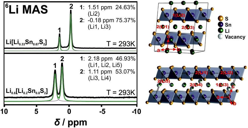 | ||
| Fig. 2 6Li NMR measurements of Li[Li0.33Sn0.67S2] (top left) and Li0.6[Li0.2Sn0.8S2] (bottom left). On the right side, each crystal structure with the labelling of the lithium atoms according to the NMR spectrum is shown. The black line corresponds to the measured spectra, the green line to the sum fit of the different curves (grey lines). | ||
The 6Li NMR spectrum of Li0.6[Li0.2Sn0.8S2] displays two signals, at 1.1 ppm and 2.2 ppm, with an integral ratio of 53:47. The different integral ratio in Li0.6[Li0.2Sn0.8S2] supports the structural difference to Li2SnS3 and can be rationalized based on the crystal structure (see Table S1, ESI† and Fig. 2, lower panel). There are five types of lithium atoms in the unit cell; two (Li1 + Li2) are within the layer and three (Li3–Li5) reside in the interlayer gallery, where Li3 and Li4 occupy octahedral positions and Li5 occupies a tetrahedral position. The labelling of each atom position is displayed in Fig. 2. In agreement with Li[Li0.33Sn0.67S2] the signal of intralayer Li is likely downfield shifted due to the Sn–S environment, hence the intralayer lithium atoms, Li1 and Li2, can be assigned to the signal at 2.2 ppm. Furthermore, we assume that Li5, which is tetrahedrally coordinated, behaves similar to the intralayer Li due to the closeness to the tin sulfide layers. The two octahedrally coordinated Li+ ions Li3 and Li4 can be assigned to the signal at 1.1 ppm. From the crystal structure we then would expect an integral ratio of 42:58. This is almost what we see in the NMR spectrum (47:53). Note that single crystal XRD data were taken at 100 K and NMR spectra were recorded at room temperature. Since we have more lithium motion at room temperature the integral ratio from NMR spectra and the occupancy ratio from XRD data are expected to not fully match.
Lithium diffusivity was investigated with 7Li PFG NMR at room temperature. Fig. 3 (upper panel) displays the diffusion coefficient DNMR as a function of the diffusion time Δ. The longer Δ, the higher is the likelihood of finite crystallite effects on the spectra, since longer diffusion paths will be probed, increasing the chance of intercrystallite diffusion of the Li+ ions. At shorter diffusion times where intracrystallite diffusion is measured, much higher diffusion coefficients are observed. This dependence on diffusion time indicates that grain boundaries have a significant effect on the transport properties as longer diffusion paths increase the possibility of crossing a grain boundary. Note that the mean free path for diffusion is on the order of ∼1 μm for diffusion times in the ms range. SEM analysis of the powder samples show that grain sizes vary between 100 μm and less than 1 μm (see Fig. S2, ESI†). This indicates that grain boundaries can affect Li+ ion diffusion at all diffusion times Δ measured here. Note that the values of the room temperature diffusion coefficient DNMR are on the order of 10−11 m2 s−1, which is notably higher than the ones reported for LGPS (∼10−12 m2 s−1).29 We converted DNMR to conductivity σNMR using the extended Nernst–Einstein relation σNMR = (DNMRnz2e2) (kBT)−1 (see ESI†). We find that for the shortest diffusion time the conductivity reaches a value of σNMR = 9.3 × 10⁻³ S cm−1. Note that for this analysis we only included interlayer lithium as participants of ion transport (see TOPOS calculations below). The overall 7Li NMR signal in the static sample consists of two unresolved components with substantially different spin–spin relaxation times T2. Only the part of the signal with the longer T2, however, contributes to the diffusion attenuation curve. That part corresponds to the lithium in the interstitial space and has been consecutively used in all further calculations related to the conductivity (see Fig. S10, ESI†). This was further confirmed by 2D exchange experiments – below ∼330 K we do not see any exchange between intra and interlayer lithium. The grain boundary conductivity of 9 × 10⁻⁴ S cm−1 (Δ = 100 ms) assessed by PFG NMR exceeds the value measured with d.c. measurements, 1.2 × 10⁻⁴ S cm−1. At an elevated temperature of 407 K, DNMR = 2.6 × 10⁻¹⁰ m2 s−1 is obtained which corresponds to σNMR = 6.7 × 10⁻² S cm−1. PFG NMR measurements at high temperatures displayed scattering effects that likely arise from the anisotropic lithium movement within the crystals. These problems have been previously observed in different anisotropic materials.30,31
 | ||
| Fig. 3 Top: Diffusion coefficient DNMR determined with PFG NMR at various diffusion times Δ. DNMR is lowered with a longer diffusion time Δ, indicating grain boundary effects in the ion transport that hinder the diffusion. The likelihood for diffusion within one crystallite and hence, bulk diffusion is higher for shorter diffusion times. Hence, ionic conductivity is higher in the bulk. For the calculation of the conductivity σNMR, the intralayer Li atoms were neglected as they are not assumed to affect the ionic conduction (see Fig. S9, ESI†). The experimental error is estimated to be 15%. Bottom: Activation energy determined by 7Li T1 relaxation time measurements in the slow motion range at varying temperatures from 320–440 K. The expected shape of the curve according to the BPP model is displayed by a dotted line. | ||
Owing to the scattering effects at high temperatures, we could not determine activation energies with PFG NMR. Further, the preparation of dense samples by sintering suitable for precise impedance spectroscopy measurements was unsuccessful. Therefore, we performed 7Li T1 relaxation time measurements in a region of slow molecular motion at varying temperatures from 320–440 K to determine activation energies (see Fig. 3).32,33 We find an activation energy of Eact = 0.17 eV that is comparable to values for the currently best LISICONs such as Li10GeP2S12 (0.21 eV) and Li11Si2PS12 (0.19 eV).12 Nevertheless, different mechanisms can be present simultaneously and we cannot determine which mechanism contributes most.
Fig. 4 summarizes the main findings of the electrical conductivity measurements (both d.c. galvanostatic polarization/depolarization and a.c. impedance spectroscopy), which were carried out at room temperature (298 K) and – due to hydration of the material in air – within an argon filled glove box using two different experimental setups with ion-blocking and non-blocking electrodes, respectively (Au|Li0.6[Li0.2Sn0.8S2]|Au and Au|LiAl|Li0.6[Li0.2Sn0.8S2]|LiAl|Au). In the first case (Fig. 4, panel a), the voltage change after switching on a d.c. current of 1 nA (at approximately t = 70 min) is characteristic of a slow polarization process due to the accumulation of mobile charge carriers at the sample/electrode interface. Note that turning off the d.c. current (at t = 400 min) results in an equally slow depolarization process. As in this case ion-blocking Au electrodes were used, this clearly indicates that the majority of mobile charge carriers in Li0.6[Li0.2Sn0.8S2] are ions. From Fig. 4a one can estimate the electronic transference number of Li0.6[Li0.2Sn0.8S2] to be less than 10−6. Further details for the calculation of the transference number are described in the ESI;† the refined evaluation shifts the upper limit of the transference number to 10−9 (see Fig. S11, ESI†). In addition, an impedance spectrum acquired in this configuration (ion blocking electrodes) is shown in Fig. S12 (ESI†): a Warburg behavior can be clearly recognized in the low frequency range. The high ionic conductivity is confirmed by the experiments which were performed in the non-blocking Au|LiAl|Li0.6[Li0.2Sn0.8S2]|LiAl|Au configuration (Fig. 4, panel b). In this case, the response of the voltage on the application of a d.c. current of 5 μA is instantaneous and corresponds to an effective Li+ ion conductivity of the sample of 1.2 × 10⁻⁴ S cm−1. In this configuration, also impedance spectroscopy measurements were carried out and a representative complex impedance spectrum is shown in Fig. 4c. Here, the spectrum is rather distorted and seems to be composed of at least two contributions. This is not surprising as the sample consists of cold-pressed powders, in which contributions from the bulk, grain boundaries, electrodes and current constrictions (between adjacent particles) can be present. It is noteworthy that, in the low frequency range, the intercept of the spectrum with the real axis (∼12500 Ω) is in good agreement with the resistance value that one can extract from the voltage change after the application of the d.c. current (in Fig. 4b the change of voltage corresponds to a resistance of 11600 Ω). By fitting the high frequency part of the spectrum with a resistance R in parallel to a constant phase element Q (from which the capacitance can be obtained as C = (R1−nQ)1/n with n being an additional fitting parameter) a capacitance value of 2.6 × 10⁻¹⁰ F is obtained, which corresponds to an apparent relative dielectric constant of 4200. Since Li0.6[Li0.2Sn0.8S2] is not expected to possess such a large dielectric constant (e.g. it is not a ferroelectric material), this large capacitance cannot be ascribed to the bulk properties of the material, but rather seems to stem from the grain-to-grain contacts. This is supported also by the fact that the extrapolation of the spectrum towards frequencies exceeding 1 MHz results in a finite intercept at about 130 Ω (see inset in Fig. 4c) which corresponds most likely to the bulk properties. The ESI† also shows an example (Fig. S13) where we extended the measuring range to 10 MHz. Then, in spite of the increased noise, the transition to the bulk semi-circle is visible. Converting this into conductivity, a value of 1.5 × 10⁻² S cm−1 is obtained, which conforms with the PFG NMR results (σNMR = 9.3 × 10⁻³ S cm−1 for Δ = 10 ms). For different samples, we observe a scatter in the enormously high conductivity, which we propose either stems from variations in the composition or in the distribution of the anisotropic grains (see Table S6, ESI†). At any rate, for optimized single crystalline conditions a conductivity of at least 10 mS cm−1 is to be expected. Note that, irrespective of these variations, the high frequency intercept of impedance spectroscopy measurement and the PFG NMR results at low Δ, which both describe bulk properties, are in good agreement in all cases. The conductivity values we obtain for our samples indicate very fast ionic bulk transport and negligible electron transport (<10−9 S cm−1), placing Li0.6[Li0.2Sn0.8S2] among the materials with the highest ionic conductivities known to date. Moreover, even including the contact resistance of the cold-pressed powder, the resulting conductivity is an order of magnitude higher than the one of related, Li rich Li[Li0.33Sn0.67S2].
 | ||
| Fig. 4 Electrical measurements on Li0.6[Li0.2Sn0.8S2] performed at 298 K under argon atmosphere: (a) and (b) display galvanostatic DC measurements of Li0.6[Li0.2Sn0.8S2] without (a) and with (b) LiAl alloy. In the LiAl configuration there is no polarization effect and the ionic conductivity can easily be determined to σ298K = 1.2 × 10⁻⁴ S cm−1. Panel (c) displays the impedance spectroscopy measurements ranging between 1 MHz and 0.01 Hz on a non-blocking configuration Au|LiAl|Li0.6[Li0.2Sn0.8S2]|LiAl|Au. The rather distorted spectrum indicates the presence of multiple contributions as expected in the case of cold pressed powders (see main text). The inset shows the finite intercept of the extrapolation of the spectrum towards frequencies exceeding 1 MHz at around 130 Ω (see also Fig. S13 in the ESI†) indicating a bulk conductivity that is two orders of magnitudes greater. The intercept of the fitted semicircle in the low frequency range most likely belongs to grain boundary resistance. The suppressed semicircle indicates the presence of a second contact resistance, which is not fitted here. Unlike the high frequency intercept, the low frequency intercept is sensitive to the pressure applied to the powder. | ||
The reason for the much higher ionic conductivity in Li depleted Li0.6[Li0.2Sn0.8S2] compared to fully occupied Li[Li0.33Sn0.67S2] is most likely connected to its crystal structure. Not only is the amount of Li between the layers decreased, giving rise to unoccupied sites which facilitate Li movement; Li was also found to occupy octahedral as well as tetrahedral sites, which already indicates that the energies associated with these sites are similar, making Li diffusion along a trajectory containing adjacent face-sharing octahedral and tetrahedral sites facile.
To further address these ideas we show difference Fourier maps (Fobs − Fcalc) of the single crystal diffraction data where no Li is modeled in the refinement (Fig. 5). It is important to keep in mind that those data were recorded at 100 K, a temperature at which Li is less mobile than at room temperature. While the Li in the octahedral layer is well localized, indeed, we find evidence for smeared out extra electron density around the tetrahedral positions. This implies that even at 100 K there is some Li mobility via the tetrahedral positions, suggesting that the ionic transport involves the tetrahedral Li sites.34 In contrast, all Li atoms are located on the octahedral positions in Li[Li0.33Sn0.67S2], which likely explains its lower conductivity. The reason as to why tetrahedral positions can be more easily occupied in Li0.6[Li0.2Sn0.8S2] than in Li[Li0.33Sn0.67S2] is most likely associated with the partial occupancy of the Li positions in the interlayer space, reducing repulsive forces due to the fewer Li atoms that have to be accommodated between the layers in Li0.6[Li0.2Sn0.8S2]. This leaves some of the octahedral sites vacant, such that Li+ ions can reside in the adjacent tetrahedral sites and interlayer diffusion pathways through face-sharing tetrahedral–octahedral–tetrahedral sites become accessible. The white dotted lines in Fig. 5 display the expected Li migration pathway according to our TOPOS calculations (see below).
 | ||
| Fig. 5 Electron density difference maps (Fobs − Fcalc) of Li0.6[Li0.2Sn0.8S2] measured at 100 K. Li was not modeled for the difference maps so that its position can be determined by means of the recorded electron density. Top: View along c at c = 0.35 (this corresponds to the layer of the tetrahedrally coordinated lithium atom, Li5). Residual electron density is observed; it partially appears from adjacent layers (octahedral lithium positions at c = 0.5 (in red) and sulfur atoms at c = 0.24 (in orange)). The Li migration pathway calculated by TOPOS is highlighted with white dotted lines. Bottom: View along c perpendicular to the ab plane at c = 0.5; the layer of octahedral Li positions. No residual electron density is observed and the Li ions are very well localized. | ||
Additionally, we performed estimates of the possible lithium migration pathways and voids with the program package TOPOS.35–37 As the program relies only on geometric and topological arguments and does not refer to the local energetics, we consider the outcome of this analysis only as providing a guideline. For this purpose, the voids in the crystal structure are calculated with the help of Voronoi–Dirichlet polyhedra and Li+ ions are assumed to be able to jump between different sites if open channels between two sites exist. A channel is considered to be accessible for lithium motion if the sum of the radii of a lithium and a framework atom (here sulfur) does not exceed the channel radius by more than 10–15%. For Li[Li0.33Sn0.67S2] we find that Li migrates through the covalent Li/SnS2 layers, along the [101] direction (see Fig. S8, ESI†). Following the calculated pathways, lithium migration is only possible passing through unoccupied tetrahedral sites. The calculation for Li0.6[Li0.2Sn0.8S2] is more difficult as TOPOS is not able to handle mixed occupancies. Therefore, we chose four different configurations: (i) all Sn/Li positions are fully occupied by tin and all interlayer positions are fully occupied by lithium, (ii) all Sn2/Li2 positions are occupied by tin and Sn1/Li1 positions as well as interlayer positions are occupied by lithium, (iii) all Sn1/Li1 positions are occupied by tin and Sn2/Li2 positions as well as interlayer positions are occupied by lithium, (iv) all tin and all lithium positions are fully occupied by lithium. All these configurations can be seen as borderline cases which only partially reflect the single-crystal X-ray structure. (Note, however, that charge balance is not considered by TOPOS and the calculations are purely geometrical in nature). Interestingly, the migration pathway analysis leads to chains along b in all four cases (see Fig. S9, ESI†). This can arise from the fact that the anion framework (here sulfur), which greatly influences the Li motion, is the same in all calculations. In contrast to Li[Li0.33Sn0.67S2] though, the migration pathway does not cross the covalent layers. The calculated migration pathway of lithium is marked by white dotted lines in the electron density maps (Fig. 5, top). These calculations lend further evidence that lithium movement is only possible via tetrahedrally coordinated sites. There is no hopping from octahedral to octahedral voids in both structures but only hopping from octahedral to tetrahedral sites and vice versa.
Conclusions
We have shown that Li0.6[Li0.2Sn0.8S2] is a fast Li+ ion conductor with a bulk conductivity of ∼10−2 S cm−1 at room temperature, exceeding electronic contributions by at least 7 orders of magnitude. This places Li0.6[Li0.2Sn0.8S2] among the best solid Li electrolyte materials known to date. While being compositionally simpler, the new superionic conductor Li0.6[Li0.2Sn0.8S2] is also structurally distinct from the known LGPS solid electrolytes and can be viewed formally as a Li sulfide-depleted version of Li[Li0.33Sn0.67S2], a recently reported Li+ ion conductor with a much lower conductivity. By analyzing the structure–property relationships in the two compounds by means of single crystal X-ray diffraction and ssNMR we demonstrate that removal of Li+ ions from the interlayer gallery significantly improves the ionic conductivity. Clearly, such partial occupancy slightly decreases the number of mobile Li+ ions while at the same time it facilitates Li+ ion motion by increasing the mobility of the Li+ ions. Therefore, besides a distinctly different Sn/Li order in the mixed Li/SnS2 layers, the Li+ ions in Li0.6[Li0.2Sn0.8S2] have more space to move, due to the slightly larger layer distance in Li0.6[Li0.2Sn0.8S2], but also due to the lower occupancy of the Li sites located in between the layers. Importantly, we show that interlayer Li does not only occupy the central octahedral but also tetrahedral sites, which is critical for facile ion movement as it opens up a Li trajectory involving face-sharing octahedral and tetrahedral voids with lower activation energies for Li hopping. In Li[Li0.33Sn0.67S2], however, Li+ ions are only found in the octahedral positions which are fully occupied, rendering movement of those Li+ ions more difficult. Our study therefore proves that the partial occupancy of interlayer cation sites in layered NaCl-analogues and Delafossite-related structure types can significantly enhance ionic conductivity as recently also seen in Na3−xSn2−xSbxNaO6.19 This effect can be very important for further studies on those materials since many Delafossite-related compounds have been reported to also exist in cation depleted versions.17,18 In the non-optimized cold-pressed samples, the transport measurements indicate high bulk conductivities (∼10−2 S cm−1) along with significant contact resistances (∼10−4 S cm−1). Given the structural anisotropy of Li0.6[Li0.2Sn0.8S2], even higher conductivity can be expected for a single crystalline sample along the ab plane. Further studies on large enough single crystals and densified sintered samples are required for a deeper analysis. As far as the applicability of the new solid electrolyte is concerned, it will be key to combine it with electrodes of moderate Li chemical potential, or to find ways of kinetic passivation. Studies along those lines are currently ongoing in our lab.Acknowledgements
We thank Marie-Luise Schreiber for ICP-AES measurements. Financial support by the Max Planck Society, Nanosystems Initiative Munich (NIM), Center for Nanoscience (CeNS) and Fonds der Chemischen Industrie is gratefully acknowledged. Work at Princeton was supported by the NSF-sponsored MRSEC at Princeton University, grant DMR-1005438. LMS gratefully acknowledge support from the Minerva fast track fellowship by the Max Planck Society.References
- U. v. Alpen, A. Rabenau and G. H. Talat, Appl. Phys. Lett., 1977, 30, 621 CrossRef.
- T. Lapp, S. Skaarup and S. Hooper, Solid State Ionics, 1983, 11, 97 CrossRef CAS.
- Y. Inaguma, C. Liquan, M. Itoh and T. Nakamura, Solid State Commun., 1993, 86, 689 CrossRef CAS.
- R. Murugan, V. Thangadurai and W. Weppner, Angew. Chem., Int. Ed., 2007, 46, 7778 CrossRef CAS PubMed.
- T. Kaib, S. Haddadpour, M. Kapitein, P. Bron, C. Schröder, H. Eckert, B. Roling and S. Dehnen, Chem. Mater., 2012, 24, 2211 CrossRef CAS.
- F. Mizuno, A. Hayashi, K. Tadanaga and M. Tatsumisago, Adv. Mater., 2005, 17, 918 CrossRef CAS.
- K. Takada, N. Aotani and S. Kondo, J. Power Sources, 1993, 43–44, 135 CrossRef.
- H. Y-P. Hong, Mater. Res. Bull., 1978, 13, 117 CrossRef.
- P. G. Bruce and A. R. West, J. Solid State Chem., 1982, 44, 354 CrossRef CAS.
- R. Kanno and M. Murayama, J. Electrochem. Soc., 2001, 148, A742 CrossRef CAS.
- N. Kamaya, K. Homma, Y. Yamakawa, M. Hirayama, R. Kanno, M. Yonemura, T. Kamiyama, Y. Kato, S. Hama, K. Kawamoto and A. Mitsui, Nat. Mater., 2011, 10, 682 CrossRef CAS.
- A. Kuhn, O. Gerbig, C. Zhu, F. Falkenberg, J. Maier and B. V. Lotsch, Phys. Chem. Chem. Phys., 2014, 16, 14669 RSC.
- A. Kuhn, T. Holzmann, J. Nuss and B. V. Lotsch, J. Mater. Chem. A, 2014, 2, 6100 CAS.
- J. A. Brant, D. M. Massi, N. A. W. Holzwarth, J. H. MacNeil, A. P. Douvalis, T. Bakas, S. W. Martin, M. D. Gross and J. A. Aitken, Chem. Mater., 2015, 27, 189 CrossRef CAS.
- K. Mizushima, P. C. Jones, P. J. Wiseman and J. B. Goodenough, Solid State Ionics, 1981, 3/4, 171 CrossRef.
- E. Plichta, M. Salomon, S. Slane and M. Uchiyama, J. Power Sources, 1987, 21, 25 CrossRef CAS.
- E. M. Seibel, J. H. Roudebush, M. N. Ali, K. A. Ross and R. J. Cava, Inorg. Chem., 2014, 53, 10989 CrossRef CAS PubMed.
- J. H. Roudebush and R. J. Cava, J. Solid State Chem., 2013, 204, 178 CrossRef CAS.
- R. W. Smaha, J. H. Roudebush, J. T. Herb, E. M. Seibel, J. W. Krizan, G. M. Fox, Q. Huang, C. B. Arnold and R. J. Cava, Inorg. Chem., 2015, 54, 7985 CrossRef CAS PubMed.
- J. E. Tanner, J. Chem. Phys., 1970, 52, 2523 CrossRef CAS.
- E. O. Stejskal and J. E. Tanner, J. Chem. Phys., 1965, 42, 288 CrossRef CAS.
- M. Bréger, M. Jiang, N. Dupré, Y. S. Meng, Y. Shao-Horn, G. Ceder and C. P. Grey, J. Solid State Chem., 2005, 178, 2575 CrossRef.
- O. A. Smirnova, V. B. Nalbandyan, A. A. Petrenko and M. Avdeev, J. Solid State Chem., 2005, 178, 1165 CrossRef CAS.
- V. V. Politaev, V. B. Nalbandyan, A. A. Petrenko, I. L. Shukaev, V. A. Volotchaev and B. S. Medvedev, J. Solid State Chem., 2010, 183, 684 CrossRef CAS.
- R. Berthelot, W. Schmidt, S. Muir, J. Eilertsen, L. Etienne, A. W. Sleight and M. A. Subramanian, Inorg. Chem., 2012, 51, 5377 CrossRef CAS PubMed.
- E. A. Zvereva, M. A. Evstigneeva, V. B. Nalbandyan, O. A. Savelieva, S. A. Ibragimov, O. S. Volkova, L. I. Medvedeva, A. N. Vasiliev, R. Klingeler and B. Buechner, Dalton Trans., 2012, 41, 572 RSC.
- C. Greaves and S. M. A. Katib, Mater. Res. Bull., 1990, 25, 1175 CrossRef CAS.
- R. D. Shannon, Acta Crystallogr., Sect. A: Cryst. Phys., Diffr., Theor. Gen. Crystallogr., 1976, 32, 751 CrossRef.
- A. Kuhn, V. Duppel and B. V. Lotsch, Energy Environ. Sci., 2013, 6, 3548 CAS.
- K. Hayamizu, Y. Aihara and N. Machida, Solid State Ionics, 2014, 259, 59 CrossRef CAS.
- K. Hayamizu, Y. Matsuda, M. Matsui and N. Imanishi, Solid State Nucl. Magn. Reson., 2015, 70, 21 CrossRef CAS PubMed.
- Y. Deng, C. Eames, J.-N. Chotard, F. Lalere, V. Seznec, S. Emge, O. Pecher, C. P. Grey, C. Masquelier and M. S. Islam, J. Am. Chem. Soc., 2015, 137, 9136 CrossRef CAS PubMed.
- L. Zhou, M. Leskes, T. Liu and C. P. Grey, Angew. Chem., Int. Ed., 2015, 54, 14782 CrossRef CAS.
- Y. Wang, W. D. Richards, S. P. Ong, L. J. Miara, J. C. Kim, Y. Mo and G. Ceder, Nat. Mater., 2015, 14, 1026 CrossRef CAS.
- V. A. Blatov, Acta Crystallogr., Sect. A: Found. Crystallogr., 2000, 56, 178 CrossRef.
- V. A. Blatov, A. P. Shevchenko and V. N. Serezhkin, J. Appl. Crystallogr., 1999, 32, 377 CrossRef.
- V. A. Blatov, IUCr Comp. Comm. Newsletter, 2006, 7, 4 Search PubMed.
- A. C. W. P. James and J. B. Goodenough, J. Solid State Chem., 1988, 74, 287 CrossRef CAS.
- J. Claverie, C. Foussier and P. Hagenmuller, Bull. Soc. Chim. Fr., 1966, 244 CAS.
- K. M. Mogare, K. Friese, W. Klein and M. Jansen, Z. Anorg. Allg. Chem., 2004, 630, 547 CrossRef CAS.
- G. Lang, Z. Anorg. Allg. Chem., 1954, 276, 77 CrossRef CAS.
Footnote |
| † Electronic supplementary information (ESI) available. See DOI: 10.1039/c6ee00633g |
| This journal is © The Royal Society of Chemistry 2016 |