 Open Access Article
Creative Commons Attribution 3.0 Unported Licence
Birnessite-type MnO2 nanosheet arrays with interwoven arrangements on vapor grown carbon fibers as hybrid nanocomposites for pseudocapacitors†
S. Chandra
Sekhar
,
Goli
Nagaraju
,
Sung Min
Cha
and
Jae Su
Yu
*
Department of Electronics and Radio Engineering, Institute for Wearable Convergence Electronics, Kyung Hee University, 1 Seocheon-dong, Giheung-gu, Yongin-si, Gyeonggi-do 446-701, Republic of Korea. E-mail: jsyu@khu.ac.kr; Fax: +82-31-206-2820; Tel: +82-31-201-3820
First published on 11th November 2016
Abstract
Manganese dioxide nanosheet arrays with interconnected arrangements are easily synthesized on vapor grown carbon fibers (MnO2 NSAs@VCFs) by a simple wet-chemical method at low temperature. The conductive nature of the VCFs serves as a scaffold and easily reduces potassium permanganate species for the formation of hierarchical MnO2 NSAs@VCFs. When utilized as an electroactive material for pseudocapacitors, the sophisticated configuration of the nanocomposite provides an effective electrochemical activity and an electron pathway for higher electrochemical performance in 1 M Na2SO4 aqueous solution. The hierarchical MnO2 NSAs@VCFs exhibit a maximum specific capacitance of 115.3 F g−1 at a current density of 0.5 A g−1 with an excellent cycling stability of 85.6% after 2000 cycles at a current density of 5 A g−1. Such facile and cost-effective fabrication of a metal oxide nanocomposite with improved electrochemical performance allows it to be considered as a promising electroactive material for energy storage devices.
1. Introduction
Nowadays, facing the challenges regarding scientific and technological problems of increasing energy consumption is the most serious issue for humanity. Also, the diminishing supply of fossil fuels is problematic as more energy is needed for many urbanizing nations.1–3 These factors are greatly influencing the power infrastructure in producing the energy needed.4 So, it is essential to develop various energy storage devices to replace swiftly depleting fossil fuels without any hazards to the environment.5–7 Among the available energy storage devices, supercapacitors have attracted a great deal of attention and are used in many electronic devices because of their light weight, reliable operation, fast charging–discharging and long lifetime.8–10 Generally, the energy storage mechanism in supercapacitors is classified into two types, i.e., electric double layer capacitors (EDLCs) and pseudocapacitors.6 In EDLCs, energy storage takes place non-faradaically by accumulating electric charge at the interface between the electrolyte and electrode material. Reduced graphene oxide, activated carbon, etc. are mostly used as active materials in EDLCs.11 Meanwhile, pseudocapacitors store electric charge at the electrode–electrolyte interface by continuous redox reactions within the active material.12 Transition metal oxides and conducting polymer based materials are generally used as an active material for pseudocapacitors.13,14 Because of the redox chemistry process, pseudocapacitive materials possess higher electrochemical performances compared to EDLC materials.15,16So far, transition metal hydroxide/oxide based nanostructures, including RuO2, Ni(OH)2, Co3O4, Ni–Co hydroxide, MnO2, etc., have been utilized as active materials in pseudocapacitors.17–21 Each of these materials has their own unique advantages and disadvantages. Among these materials, MnO2 especially has been considered as a promising candidate for use in pseudocapacitors because of its high theoretical capacitance, low cost, environmentally-friendly feature and abundant availability in nature. Accordingly, MnO2 based nanostructures with various morphologies such as nanowires, nanosheets, and flower-like structures have been prepared under various growth methods for pseudocapacitors.22–25 The relatively low electrical conductivity of MnO2 leads to the use of a small amount of material during the electrochemical process, which results in a lower capacitance. However, there have been some obstacles in the fabrication of MnO2 based supercapacitors.26,27 To improve the capacitance performance, doping of MnO2 with different metals or incorporation of conductive additives such as carbon nanotubes, graphene oxide, conducting polymers, etc. is essential.28,29 Although MnO2 transition metal hybrid composites have high capacitance, they cause a loss of capacitance during the cycling process.30 Therefore, finding a novel and cost-effective conductive material to be incorporated into MnO2 is a promising approach to improve the electrochemical performance.31 Of several conducting materials, vapor grown carbon fibers (VCFs) are considered as an effective candidate because of their abundance, low cost, good electrical conductivity, highly accessible surface and robust electrochemical resistibility against several electrolytes.32,33 Therefore, the incorporation of VCFs into MnO2 could be expected to offer a better capacitive performance.
In this work, we report a simple and cost-effective approach to synthesize a hybrid composite of MnO2 nanosheet arrays coated onto VCFs (MnO2 NSAs@VCFs) by a wet-chemical method. The as-prepared composite provides unique properties including good electrical conductivity and open porous structure, which are favorable for the intercalation–deintercalation of electrolyte ions with the electrochemically active species. Thus, a higher electrochemical performance including excellent cycling stability is presented.
2. Experimental section
2.1 Chemicals
VCFs were purchased from Showa Denko K.K, Japan. Potassium permanganate (KMnO4, ACS reagent, ≥99.0%), sulfuric acid (H2SO4) (99.999% pure), nitric acid (HNO3) and sodium sulfate (Na2SO4) were purchased from Sigma Aldrich Corp., South Korea. Polyvinylidene fluoride (PVdF, –(C2H2F2)n–) and N-methyl-2-pyrrolidone (NMP, C5H9NO) were obtained from Daejung Chemicals Ltd, South Korea.2.2 Synthesis of MnO2 NSAs@VCFs
The hierarchical MnO2 NSAs@VCFs nanocomposite was synthesized via a simple and green wet-chemical method. At first, the VCFs were acid-treated with nitric acid under reflux condition for 6 h for functionalization. After that, the VCFs were cleaned with de-ionized (DI) water several times to remove the acidic species and dried at 60 °C for 2 h. Then, the acid-treated VCFs (50 mg) were dispersed in a beaker containing 100 ml of DI water and 25 mM of KMnO4 was added to the above solution under magnetic stirring. After 10 min, 1 ml of H2SO4 was added dropwise to the above mixture and heated at 80 °C for 6 h on a hotplate under vigorous stirring. Finally, the precipitate was collected by washing with water after it cooled down to room temperature (RT) and was dried at 60 °C overnight.2.3 Characterization
The surface morphologies of the MnO2 NSAs@VCFs were characterized using a field-emission scanning electron microscope (FE-SEM, Carl Zeiss, LEO SUPRA 55) equipped with an energy-dispersive X-ray spectrometer (EDX). The crystallinity of a prepared sample was observed by using an X-ray diffractometer (XRD, M18XHF-SRA, Mac Science Ltd) with Cu Kα radiation (λ = 0.15406). Raman spectra of the prepared samples were analyzed using a high-resolution Raman spectrometer (HR-Raman Spectrometer, inVia) employing an argon ion laser with an incident wavelength of 514 nm.2.4 Electrochemical measurements
The electrochemical properties of the MnO2 NSAs@VCFs were characterized by using an IVIUMSTAT electrochemical workstation (IVIUM Technologies) in a three electrode system at RT. Cyclic voltammetry (CV), galvanic charge–discharge (GCD) and electrochemical impedance spectroscopy (EIS) measurements were conducted using the synthesized MnO2 NSAs@VCFs composite coated carbon cloth as a working electrode, platinum wire as a counter electrode and Ag/AgCl as a reference electrode in 1 M Na2SO4 electrolyte solution. Here, the working electrode was prepared by mixing 80 wt% of MnO2 NSAs@VCFs, 10 wt% of super P carbon black and 10 wt% of PVdF as a binder. The mixture was well ground using an agate mortar and then NMP solvent was added dropwise to form a slurry. The obtained slurry was then coated uniformly on the piece of carbon cloth (1 × 1 cm2) and dried at RT. After drying, the electrodes were placed on a hotplate at 120 °C for 3 h. The specific capacitance of the active material was calculated using the following formula:34,35 | (1) |
3. Results and discussion
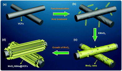
Fig. 1 shows a schematic diagram of the fabrication procedure for MnO2 NSAs@VCFs. Here, cost-effective, anticorrosive and electrically conductive VCFs were chosen as a scaffold for the growth of MnO2 NSAs (Fig. 1(a)). Initially, the VCFs were acid-treated to enhance the dispersion and to decrease the hydrophobic nature and van der Waals forces among them, as shown in Fig. 1(b). The as-functionalized VCFs were mixed with KMnO4 to prepare the MnO2 NSAs. The VCFs served as a sacrificial reductant and the KMnO4 acted as an oxidant, with the intention to convert the dissolved Mn7+ to Mn4+. As a result, the insoluble MnO2 NSAs were deposited on the surface of the VCFs. During the synthesis, a few drops of H2SO4 were added to the growth solution, which led to the uniform dissolution of VCFs in DI water and provided a higher degree of oxidation to the VCFs. Then, the permanganate (MnO4−) ions were gradually absorbed and precipitated on the surface of the oxidized VCFs via an interaction between the remaining KMnO4 and the hydroxyl groups of VCFs under the thermal conditions as shown in Fig. 1(c). The formation of MnO2 NSAs@VCFs during this synthesis process is demonstrated by the following equation:36,37 | (2) |
The redox reaction between the KMnO4 and VCFs occurred slowly in the solution under stirring at RT. Upon heating at 80 °C, the growth rate increased rapidly, which resulted in the formation of MnO2 NSAs on the VCF surfaces as shown in Fig. 1(d). Meanwhile, under neutral growth conditions without the addition of H2SO4 to the growth solution, the KMnO4 acted as a ‘weak oxidizing agent’ due to the much lower positive electrode potential than that found under acidic conditions. Such conditions are unfavorable for the reduction of MnO4− ions by water.36 In addition, in the absence of the VCFs in the growth solution, we did not observe any product after the completion of the growth process. This indicates that the VCFs not only play a crucial role in reducing the KMnO4 under acidic conditions, but are also helpful in the growth of the MnO2 NSAs on their surfaces.
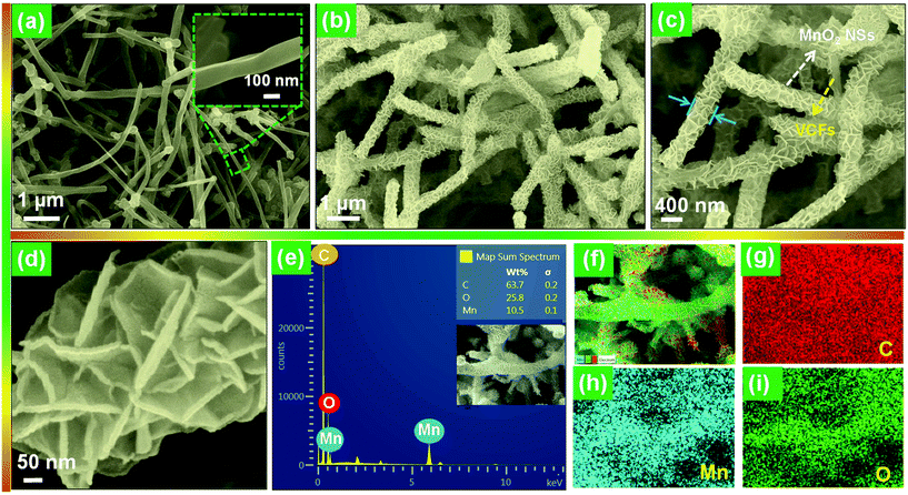
The morphologies of the bare VCFs and the hierarchical MnO2 NSAs@VCFs composite are shown in Fig. 2. As shown in Fig. 2(a), the VCFs showed a regular fiber-like structure and their diameter was found to be ∼120 nm. After completion of the growth process, as displayed in Fig. 2(b), the prepared sample was uniformly decorated on the surface of VCFs. As can be clearly seen in the increased magnification image (Fig. 2(c)), forest-like MnO2 NSAs were densely gathered on the VCFs, to give an increased diameter of ∼415 nm as compared to the bare VCFs. This indicates that a MnO2 NSA layer had a height of ∼295 nm. Moreover, each NSA had a thickness of around 16–22 nm as shown in Fig. 2(d). From the EDX analysis of the MnO2 NSAs@VCFs composite (Fig. 2(e)), it can be observed that the presence of Mn, O and C was quite evident without any impurities. Also, the elemental mapping images showed that Mn and O elements were uniformly distributed on the VCFs, which have a high C content as shown in Fig. 2(f).
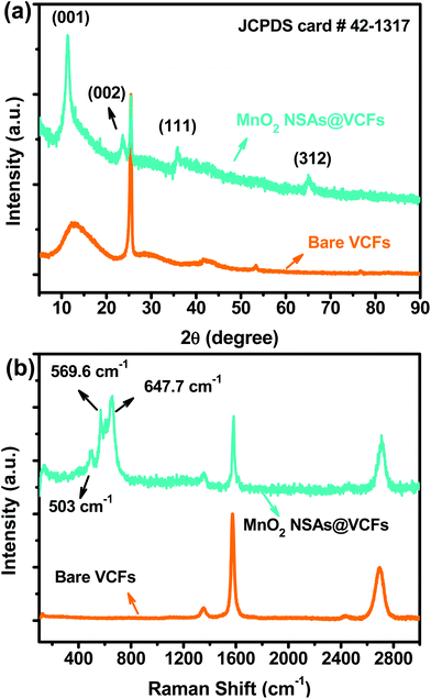
The crystalline structure of the prepared material was characterized by XRD analysis. Fig. 3(a) shows the XRD patterns of the bare VCFs and the MnO2 NSAs@VCFs composite. For the bare VCFs, the XRD pattern revealed broad peaks at 2θ degrees of 12.7, 41.5, 53.3 and 76.7° and a sharp peak at 25.4°, which are characteristic of a carbon based material.38 Meanwhile, the MnO2 NSAs@VCFs composite exhibited four peaks at 12, 24.1, 36.8 and 66.2° which are indexed to the crystal planes of (001), (002), (111) and (312) for MnO2, indicating the birnessite-type structure of the material (JCPDS card # 42-1317).39 The structural properties of the as-prepared MnO2 NSAs@VCFs composite were further analyzed by HR Raman spectroscopy as shown in Fig. 3(b). It is well known that acid-treated VCFs have a carbon content illustrated by the Raman bands of D, G and G0 at 1353, 1572 and 2695 cm−1, respectively. However, the MnO2 NSAs@VCFs composite showed additional vibrational Raman peaks at 503, 569.6 and 647.7 cm−1, which are ascribed to the presence of the birnessite-type MnO2. These results clearly demonstrate that the MnO2 NSAs were successfully grown on the VCFs without any impurities.
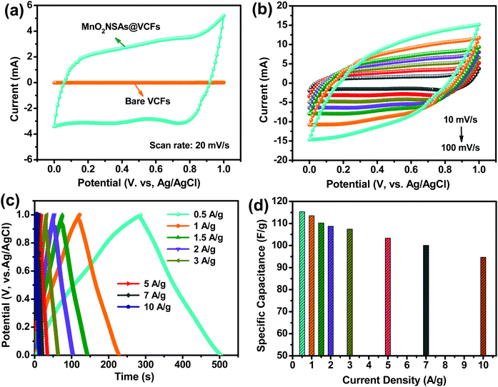
The electrochemical properties of the MnO2 NSAs@VCFs composite material was investigated using a three-electrode system in a 1 M Na2SO4 electrolyte solution at RT. Fig. 4(a) shows the comparison between the CV curves of the bare VCFs and the MnO2 NSAs@VCFs at a scan rate of 20 mV s−1. It can be seen that the bare VCFs showed no/slight response in current, indicating that the contribution of the VCFs to the capacitance is negligible. However, the CV curve of the MnO2 NSAs@VCFs exhibited relatively high integral CV areas and good rectangular and symmetric shapes, suggesting the fast and reversible surface redox reactions of ideal pseudocapacitive behavior. Usually, in many cases, the specific capacitance is proportional to the integrating area of the CV curve at the same scanning rate.37 So, it was found that the formed MnO2 NSAs@VCFs exhibited a higher capacitance than the pristine VCFs and also increased the rate of faradaic reactions due to the increased surface area. Fig. 4(b) shows the CV curves of the MnO2 NSAs@VCFs at different scan rates. It was noticed that the CV curves were enlarged without any distortion of their shapes as the scan rate was increased from 10 to 100 mV s−1. The excellent electrochemical reversibility of the composite is mainly due to its hierarchical architecture and good electrical conductivity, which contributes to the fast intercalation of electrolyte cations (Na+) with the material during reduction and deintercalation upon oxidation.40,41 The GCD analysis was carried out to further confirm the higher electrochemical performance of the composite electrode. Fig. 4(c) shows the GCD curves of the hierarchical MnO2 NSAs@VCFs electrode between 0 to 1.0 V at different current densities in a 1 M Na2SO4 electrolyte solution. The symmetric nature of all the charge–discharge cycles again shows linear and symmetrical features, demonstrating excellent reversibility and pseudocapacitive nature. The specific capacitance for each GCD curve was calculated from eqn (1) as mentioned above. Interestingly, the MnO2 NSAs@VCFs composite exhibited specific capacitance values of 115.3, 113.5, 110.2, 108.7, 107.4, 103.3, 100 and 94.7 F g−1 at different current densities of 0.5, 1, 1.5, 2, 3, 5, 7 and 10 A g−1, respectively. The corresponding specific capacitance value as a function of applied current density is plotted in Fig. 4(d). The specific capacitance decreased gradually as the current density increased. This is either because the electrolyte ions are only absorbed on the outer surface of the material or an insufficient portion of the material is involved in the electrochemical reactions during the quick charge–discharge process. Meanwhile, the electrolyte ions can diffuse deeply inside the active material at a low current density, which results in a higher energy storage performance.42 But still, the composite material showed a rate capability of 82.1% at a current density of 10 A g−1, proving the advantages of composite materials for high-rate pseudocapacitors. The maximum capacitance of the MnO2 NSAs@VCFs composite is higher or comparable to those previously reported, as shown in Table S1.†
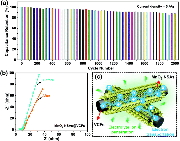
The cycling stability is also one of the crucial factors which determine the suitability of active materials for practical applications. Accordingly, the long-term cycling process of the MnO2 NSAs@VCFs electrode was carried out via repetitive GCD cycles at a high current density of 5 A g−1 in a 1 M Na2SO4 electrolyte solution. The variation in the capacitance retention with increasing the cycle number up to 2000 cycles for the MnO2 NSAs@VCFs composite electrode is displayed in Fig. 5(a). After 2000 cycles, the composite material still exhibited a capacitance retention of 85.6%, indicating the long-term cycling stability of the composite material for practical applications. The electrochemical behavior and conductivity of the hierarchical MnO2 NSAs@VCFs composite was investigated using EIS analysis over a frequency range of 0.01 Hz to 100 kHz with a perturbation amplitude of 5 mV versus open-circuit potential. Fig. 5(b) shows the Nyquist plots of the MnO2 NSAs@VCFs before and after the long-term cycling process. The plot includes a semicircle in the high frequency region and a sloped line in the low frequency region. The sloped lines (Warburg impedance) for both the curves are due to the ion transportation between the electrolyte and electrode depending on the frequency. Before cycling, the equivalent series resistance (electrolyte resistance, electrode resistance and contact resistance between the electrolyte and electrode), which is measured from the intercept of the curve with the real axis, was observed as 5.05 Ω. But, after completion of the cycling test, this value was slightly increased to 6.13 Ω which may be due to the formation of a solid electrolyte interface. This would act as an obstacle between the active material and electrolyte. The charge transfer resistance (Rct) between the electrolyte and active material was measured from the diameter of the semicircle shape of the curve. The Rct value of the composite electrode before cycling was 3.46 Ω and, after cycling, it was about 3.67 Ω, which still remains low. This is indicative of the excellent electrochemical conductivity of the MnO2 NSAs@VCFs composite even after a long-term cycling process. The higher capacitance, rate capability and cycling stability of the composite electrode could be due to the following structural features, as schematically illustrated in Fig. 5(c). At first, the VCFs provide higher conductivity and can be beneficial for the formation of continuous charge transfer pathways. The hierarchical and ultrathin characteristics of the MnO2 NSAs on the VCFs increase the surface area, making them completely available to absorb the electrolyte ions (Na+) for reversible electrochemical reactions via faster electron and ion transport. Moreover, the electrolyte Na+ ions can easily penetrate into the small gaps formed by the interwoven arrangement of the MnO2 NSAs on the surface of the VCFs, which results in enhanced electrochemical kinetics and improved energy storage properties. All in all, this cost-effective approach to fabricate electrochemically conductive composite materials paves a new pathway for high-performance supercapacitor applications.
4. Conclusion
In summary, hierarchical MnO2 NSAs@VCFs composite materials were synthesized by a simple and green wet-chemical method at low temperature. Cost-effective VCFs provided a good conductive surface and helped MnO2 NSA growth over the top of them. The interconnected arrangement of the ultrathin MnO2 NSAs@VCFs leads to high surface area and good electrochemical conductivity to exhibit the higher electrochemical performance as a pseudocapacitive material in a 1 M Na2SO4 electrolyte solution. The maximum specific capacitance based on the active material weight was about 115.3 F g−1 at 0.5 A g−1 for the MnO2 NSAs@VCFs composite. Moreover, the fabricated material composite also showed good rate capability and cycling stability at higher current densities. Consequently, the prepared composite material is a promising candidate for high-performance energy storage applications.Acknowledgements
This work was supported by the National Research Foundation of Korea (NRF) grant funded by the Korea government (MSIP) (No. 2015R1A5A1037656).References
- Z. Gao, C. Bumgardner, N. Song, Y. Zhang, J. Li and X. Li, Nat. Commun., 2016, 7, 11586 CrossRef CAS PubMed.
- T. Chen and L. Dai, Mater. Today, 2013, 16, 272–280 CrossRef CAS.
- P. Simon and Y. Gogotsi, Nat. Mater., 2008, 7, 845–854 CrossRef CAS PubMed.
- X. Luo, J. Wang, M. Dooner and J. Clarke, Appl. Energy, 2015, 137, 511–536 CrossRef.
- A. S. Arico, P. Bruce, B. Scrosati, J.-M. Tarascon and W. van Schalkwijk, Nat. Mater., 2005, 4, 366–377 CrossRef CAS PubMed.
- J. Jiang, Y. Li, J. Liu, X. Huang, C. Yuan and X. W. Lou, Adv. Mater., 2012, 24, 5166–5180 CrossRef CAS PubMed.
- G. Nagaraju, S. M. Cha, S. C. Sekhar and J. S. Yu, Adv. Energy Mater. DOI:10.1002/aenm.201601362.
- M. M. Shaijumon, F. S. Ou, L. Ci and P. M. Ajayan, Chem. Commun., 2008, 2373–2375, 10.1039/b800866c.
- G. Xu, B. Ding, J. Pan, J. Han, P. Nie, Y. Zhu, Q. Sheng and H. Dou, J. Mater. Chem. A, 2015, 3, 23268–23273 CAS.
- J. Cherusseri and K. K. Kar, J. Mater. Chem. A, 2015, 3, 21586–21598 CAS.
- J. Vatamanu, M. Vatamanu and D. Bedrov, ACS Nano, 2015, 9, 5999–6017 CrossRef CAS PubMed.
- G. K. Veerasubramani, K. Krishnamoorthy and S. J. Kim, RSC Adv., 2015, 5, 16319–16327 RSC.
- P. Y. Chan, Rusi and S. R. Majid, Solid State Ionics, 2014, 262, 226–229 CrossRef CAS.
- E. Frackowiak, Phys. Chem. Chem. Phys., 2007, 9, 1774–1785 RSC.
- M. Rajkumar, C.-T. Hsu, T.-H. Wu, M.-G. Chen and C.-C. Hu, Prog. Nat. Sci.: Mater. Int., 2015, 25, 527–544 CrossRef CAS.
- J. Ji, L. L. Zhang, H. Ji, Y. Li, X. Zhao, X. Bai, X. Fan, F. Zhang and R. S. Ruoff, ACS Nano, 2013, 7, 6237–6243 CrossRef CAS PubMed.
- A. L. M. Reddy and S. Ramaprabhu, J. Phys. Chem. C, 2007, 111, 7727–7734 CAS.
- Y. Liu, R. Wang and X. Yan, Sci. Rep., 2015, 5, 11095 CrossRef PubMed.
- G. Nagaraju, Y. H. Ko and J. S. Yu, J. Power Sources, 2015, 283, 251–259 CrossRef CAS.
- G. Nagaraju, G. S. R. Raju, Y. H. Ko and J. S. Yu, Nanoscale, 2016, 8, 812–825 RSC.
- S. Chen, J. Zhu, X. Wu, Q. Han and X. Wang, ACS Nano, 2010, 4, 2822–2830 CrossRef CAS PubMed.
- R. Jiang, T. Huang, J. Liu, J. Zhuang and A. Yu, Electrochim. Acta, 2009, 54, 3047–3052 CrossRef CAS.
- X. Zhang, J. Ma, W. Yang, Z. Gao, J. Wang, Q. Liu, J. Liu and X. Jing, CrystEngComm, 2014, 16, 4016–4022 RSC.
- S. Zhu, W. Cen, L. Hao, J. Ma, L. Yu, H. Zheng and Y. Zhang, Mater. Lett., 2014, 135, 11–14 CrossRef CAS.
- S. Maiti, A. Pramanik and S. Mahanty, ACS Appl. Mater. Interfaces, 2014, 6, 10754–10762 CAS.
- X. Lu, M. Yu, G. Wang, T. Zhai, S. Xie, Y. Ling, Y. Tong and Y. Li, Adv. Mater., 2013, 25, 267–272 CrossRef CAS PubMed.
- G. Yu, L. Hu, N. Liu, H. Wang, M. Vosgueritchian, Y. Yang, Y. Cui and Z. Bao, Nano Lett., 2011, 11, 4438–4442 CrossRef CAS PubMed.
- H. Xia, Y. Wang, J. Lin and L. Lu, Nanoscale Res. Lett., 2012, 7, 1 CrossRef PubMed.
- T. Takei, A. Miura and N. Kumada, Colloids Surf., A, 2012, 396, 341–345 CrossRef CAS.
- A.-Q. Zhang, Y.-H. Xiao, L.-Z. Lu, L.-Z. Wang and F. Li, J. Appl. Polym. Sci., 2013, 128, 1327–1331 CAS.
- J. M. Ko and K. M. Kim, Mater. Chem. Phys., 2009, 114, 837–841 CrossRef CAS.
- J.-H. Jeong and E.-S. Oh, J. Appl. Electrochem., 2015, 45, 983–990 CrossRef CAS.
- I. Cho, J. Choi, K. Kim, M.-H. Ryou and Y. M. Lee, RSC Adv., 2015, 5, 95073–95078 RSC.
- G. Nagaraju, Y. H. Ko, S. M. Cha, S. H. Im and J. S. Yu, Nano Res., 2016, 9, 1507–1522 CrossRef CAS.
- G. Nagaraju, Y. H. Ko and J. S. Yu, CrystEngComm, 2014, 16, 11027–11034 RSC.
- Y. Chen, Y. Zhang, D. Geng, R. Li, H. Hong, J. Chen and X. Sun, Carbon, 2011, 49, 4434–4442 CrossRef CAS.
- L. Li, Z. A. Hu, N. An, Y. Y. Yang, Z. M. Li and H. Y. Wu, J. Phys. Chem. C, 2014, 118, 22865–22872 CAS.
- H. Xia, Y. Wang, J. Lin and L. Lu, Nanoscale Res. Lett., 2012, 7, 1–10 CrossRef PubMed.
- P. Wu, S. Cheng, L. Yang, Z. Lin, X. Gui, X. Ou, J. Zhou, M. Yao, M. Wang, Y. Zhu and M. Liu, ACS Appl. Mater. Interfaces, 2016, 8, 23721–23728 CAS.
- M. Toupin, T. Brousse and D. Bélanger, Chem. Mater., 2004, 16, 3184–3190 CrossRef CAS.
- D. Guo, X. Yu, W. Shi, Y. Luo, Q. Li and T. Wang, J. Mater. Chem. A, 2014, 2, 8833–8838 CAS.
- G. Nagaraju, R. Kakarla, S. M. Cha and J. S. Yu, Nano Res., 2015, 8, 3749–3763 CrossRef CAS.
Footnote |
| † Electronic supplementary information (ESI) available. See DOI: 10.1039/c6dt03751h |
| This journal is © The Royal Society of Chemistry 2016 |

