 Open Access Article
Creative Commons Attribution 3.0 Unported Licence
Regioisomerism in cationic sulfonyl-substituted [Ir(C^N)2(N^N)]+ complexes: its influence on photophysical properties and LEC performance†
Cathrin D.
Ertl
a,
Lidón
Gil-Escrig
b,
Jesús
Cerdá
b,
Antonio
Pertegás
b,
Henk J.
Bolink
b,
José M.
Junquera-Hernández
b,
Alessandro
Prescimone
a,
Markus
Neuburger
a,
Edwin C.
Constable
a,
Enrique
Ortí
*b and
Catherine E.
Housecroft
*a
aDepartment of Chemistry, University of Basel, Spitalstrasse 51, CH-4056 Basel, Switzerland. E-mail: catherine.housecroft@unibas.ch
bInstituto de Ciencia Molecular, Universidad de Valencia, Catedrático José Beltrán 2, Paterna, E-46980, Spain. E-mail: enrique.orti@uv.es
First published on 12th May 2016
Abstract
A series of regioisomeric cationic iridium complexes of the type [Ir(C^N)2(bpy)][PF6] (bpy = 2,2′-bipyridine) is reported. The complexes contain 2-phenylpyridine-based cyclometallating ligands with a methylsulfonyl group in either the 3-, 4- or 5-position of the phenyl ring. All the complexes have been fully characterized, including their crystal structures. In acetonitrile solution, all the compounds are green emitters with emission maxima between 493 and 517 nm. Whereas substitution meta to the Ir–C bond leads to vibrationally structured emission profiles and photoluminescence quantum yields of 74 and 77%, placing a sulfone substituent in a para position results in a broad, featureless emission band, an enhanced quantum yield of 92% and a shorter excited-state lifetime. These results suggest a larger ligand-centred (3LC) character of the emissive triplet state in the case of meta substitution and a more pronounced charge transfer (CT) character in the case of para substitution. Going from solution to the solid state (powder samples and thin films), the emission maxima are red-shifted for all the complexes, resulting in green-yellow emission. Data obtained from electrochemical measurements and density functional theory calculations parallel the photophysical trends. Light-emitting electrochemical cells (LECs) based on the complexes were fabricated and evaluated. A maximum efficiency of 4.5 lm W−1 at a maximum luminance of 940 cd m−2 was observed for the LEC with the complex incorporating the sulfone substituent in the 4-position when operated under pulsed current driving conditions.
Introduction
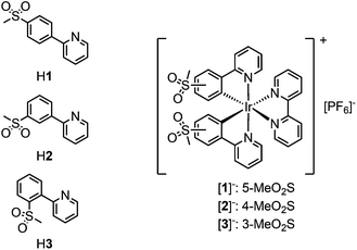
Ionic transition metal complexes (iTMCs),1,2 in particular bis-cyclometallated cationic iridium(III) complexes of the type [Ir(C^N)2(N^N)]+, are promising candidates for application in light-emitting electrochemical cells (LECs) and have therefore been intensely studied as emissive materials. In this class of iridium emitters, high quantum yields are possible with emission colours spanning the whole visible spectrum, combined with high stability of the complexes.3,4 Emission colour tuning is possible by varying the cyclometallating (C^N) ligands as well as the ancillary (N^N) ligand. The frontier orbitals in these types of complexes are spatially separated, with the HOMO being located mainly on the iridium centre and the C^N ligands and the LUMO on the N^N ligand.5–7 An increase in the HOMO–LUMO gap and a resulting blue-shift in the emission maximum are therefore achieved by the combination of electron-withdrawing substituents on the C^N ligands and electron-donating groups on the N^N ligand.3,4,8While fluorine substituents have been widely used as electron-withdrawing groups on the cyclometallating ligands,9–12 the use of sulfone groups has remained limited. Most examples of sulfone-substituted cyclometallating ligands in iridium complexes are those of neutral emitters used in organic light-emitting diodes (OLEDs).13–19 Recently, we have reported the synthesis and characterization of cationic [Ir(C^N)2(N^N)]+ complexes containing sulfone-substituted phenylpyrazole20 or phenylpyridine ligands,21–23 which give promising performances in LECs. In comparison with the archetypal [Ir(ppy)2(bpy)][PF6]24 (Hppy = 2-phenylpyridine, bpy = 2,2′-bipyridine), replacement of Hppy by 2-(4-methylsulfonylphenyl)pyridine (H1) leads to a 92 nm blue-shift of the emission maximum in MeCN solution (complex [Ir(1)2(bpy)][PF6] in Scheme 1).22
With the aim of achieving blue emission, we recently reported the synthesis of a series of iridium complexes with 2-(4-methylsulfonylphenyl)pyridine (H1) and 2-(3-methylsulfonylphenyl)pyridine (H2) as cyclometallating ligands and electron-rich pyrazolylpyridine as the diimine N^N ligand.23 Surprisingly, a difference of ∼30 nm in the emission maximum was observed on changing the substitution position of the sulfone group.
There have been few investigations on the influence of the substitution position of ligand functionalities on the properties of [Ir(C^N)2(N^N)]+ complexes. Examples include the introduction of diphenylamino,25 fluoro,26 methyl,27 trifluoromethyl,28,29 methylpyridinium,30 bromo and fluorenyl31 and benzylsulfonyl15 groups in the 3-, 4- and 5-positions of the cyclometallating phenyl ring. In all of these studies, except for the one investigating bromo and fluorenyl groups,31 it was found that substitution in the 4-position, i.e. para to the Ir–C bond, has the largest influence on emission colour. This observation was supported by density functional theory (DFT) calculations.27 In most of the cases, however, cyclometallating ligands with substituents in the 5-position, meta to the Ir–C bond, have been used. Only a few examples of iridium complexes with substituents in the 4-position of the cyclometallating ligands have been reported,32,33 and even fewer with substituents in the 3-position.34
Herein, we report the synthesis of a series of [Ir(C^N)2(bpy)][PF6] complexes with methylsulfonyl groups in the 3-, 4- and 5-positions of the phenyl ring of the cyclometallating ligands (Scheme 1). The effect of the substitution position on the photophysical and electrochemical properties was investigated and further analysed with the help of DFT calculations. The electroluminescence properties of the complexes have been investigated in LEC devices operated under pulsed driving conditions.
Experimental
General
Microwave reactions were carried out in a Biotage Initiator 8 reactor. 1H and 13C{1H} NMR spectra as well as 2D NMR spectra were recorded on a Bruker Avance III-500 spectrometer at 295 K; chemical shifts were referenced to residual solvent peaks with δ (TMS) = 0 ppm. For electrospray ionization (ESI) and LC-ESI mass spectra, a Bruker Esquire 3000plus spectrometer and a combination of Shimadzu (LC) and Bruker AmaZon X instruments were used, respectively. FT-IR spectra were recorded on a Perkin Elmer Spectrum Two UATR instrument. Absorption spectra were recorded on an Agilent 8453 spectrophotometer and solution emission spectra on a Shimadzu 5301PC spectrofluorophotometer. Solution and powder photoluminescence quantum yields were recorded on a Hamamatsu absolute PL quantum yield spectrometer, C11347 Quantaurus QY. Emission spectra of powder samples as well as solution and powder excited-state lifetime measurements were carried out using a Hamamatsu Compact Fluorescence Lifetime spectrometer, C11367 Quantaurus Tau. The photoluminescence (PL) properties (spectra and quantum yields) in thin films were measured using a Hamamatsu absolute quantum yield C9920. Electrochemical measurements were performed using cyclic and square wave voltammetry on a CH Instruments 900B potentiostat with glassy carbon working and platinum auxiliary electrodes; a silver wire was used as a pseudo-reference electrode. Dry, purified CH3CN was used as the solvent and 0.1 M [nBu4N][PF6] as the supporting electrolyte. Ferrocene as an internal reference was added at the end of each experiment.Synthesis
The synthesis of [Ir(1)2(bpy)][PF6],22 2-(3-methylsulfonylphenyl)pyridine (H2)23 and [Ir(2)2Cl]2![[thin space (1/6-em)]](https://www.rsc.org/images/entities/char_2009.gif) 23 has been reported previously. 2-(2-Methylsulfonylphenyl)pyridine (H3) was prepared according to a literature method and 1H NMR data matched those reported.35,36 Silica was purchased from Fluka (silica gel 60, 0.040–0.063 mm).
23 has been reported previously. 2-(2-Methylsulfonylphenyl)pyridine (H3) was prepared according to a literature method and 1H NMR data matched those reported.35,36 Silica was purchased from Fluka (silica gel 60, 0.040–0.063 mm).
![[thin space (1/6-em)]](https://www.rsc.org/images/entities/char_2009.gif) :
:![[thin space (1/6-em)]](https://www.rsc.org/images/entities/char_2009.gif) 1, 4 mL) in a microwave vial and purged with N2. IrCl3·xH2O (ca. 82%, 307 mg, 0.842 mmol) was added and the mixture was heated at 110 °C for 1.5 h in a microwave reactor (2 bar). The resulting precipitate was filtered off, washed with H2O and EtOH, and redissolved in DCM and the solvent was removed under reduced pressure. The orange precipitate formed in the filtrate was filtered off, washed with EtOH, and redissolved with DCM and the solvent removed. Both residues were combined to yield the product as a brownish-orange solid (424 mg, 0.306 mmol, 80.5%). 1H NMR (500 MHz, CDCl3) δ/ppm 9.33 (pseudo-dt, J = 8.5, 1.1 Hz, 4H, HB3), 9.14 (ddd, J = 5.8, 1.8, 0.8 Hz, 4H, HB6), 7.92 (ddd, J = 8.5, 7.4, 1.7 Hz, 4H, HB4), 7.62 (dd, J = 7.7, 1.1 Hz, 4H, HA4), 6.90 (ddd, J = 7.3, 5.7, 1.4 Hz, 4H, HB5), 6.69 (pseudo-t, J = 7.8 Hz, 4H, HA5), 5.88 (dd, J = 7.9, 1.1 Hz, 4H, HA5), 3.22 (s, 12H, HMe). IR (solid,
1, 4 mL) in a microwave vial and purged with N2. IrCl3·xH2O (ca. 82%, 307 mg, 0.842 mmol) was added and the mixture was heated at 110 °C for 1.5 h in a microwave reactor (2 bar). The resulting precipitate was filtered off, washed with H2O and EtOH, and redissolved in DCM and the solvent was removed under reduced pressure. The orange precipitate formed in the filtrate was filtered off, washed with EtOH, and redissolved with DCM and the solvent removed. Both residues were combined to yield the product as a brownish-orange solid (424 mg, 0.306 mmol, 80.5%). 1H NMR (500 MHz, CDCl3) δ/ppm 9.33 (pseudo-dt, J = 8.5, 1.1 Hz, 4H, HB3), 9.14 (ddd, J = 5.8, 1.8, 0.8 Hz, 4H, HB6), 7.92 (ddd, J = 8.5, 7.4, 1.7 Hz, 4H, HB4), 7.62 (dd, J = 7.7, 1.1 Hz, 4H, HA4), 6.90 (ddd, J = 7.3, 5.7, 1.4 Hz, 4H, HB5), 6.69 (pseudo-t, J = 7.8 Hz, 4H, HA5), 5.88 (dd, J = 7.9, 1.1 Hz, 4H, HA5), 3.22 (s, 12H, HMe). IR (solid, ![[small nu, Greek, tilde]](https://www.rsc.org/images/entities/i_char_e0e1.gif) /cm−1) 2928 (w), 1604 (w), 1561 (w), 1474 (m), 1422 (w), 1395 (w), 1290 (m), 1274 (m), 1256 (m), 1154 (m), 1129 (s), 1067 (m), 961 (m), 786 (m), 755 (m), 736 (m), 722 (m), 709 (m), 646 (w), 586 (w), 573 (w), 551 (w), 537 (s), 527 (s), 488 (s), 465 (m). LC-ESI-MS m/z 657.1 [Ir(C^N)2]+ (calc. 657.1), 698.1 [Ir(C^N)2(MeCN)]+ (calc. 698.1), 739.0 [Ir(C^N)2(MeCN)2]+ (calc. 739.1). Found C 40.62, H 3.28, N 4.08; C48H40Cl2Ir2N4O8S4·2H2O requires C 40.59, H 3.12, N 3.94%.
/cm−1) 2928 (w), 1604 (w), 1561 (w), 1474 (m), 1422 (w), 1395 (w), 1290 (m), 1274 (m), 1256 (m), 1154 (m), 1129 (s), 1067 (m), 961 (m), 786 (m), 755 (m), 736 (m), 722 (m), 709 (m), 646 (w), 586 (w), 573 (w), 551 (w), 537 (s), 527 (s), 488 (s), 465 (m). LC-ESI-MS m/z 657.1 [Ir(C^N)2]+ (calc. 657.1), 698.1 [Ir(C^N)2(MeCN)]+ (calc. 698.1), 739.0 [Ir(C^N)2(MeCN)2]+ (calc. 739.1). Found C 40.62, H 3.28, N 4.08; C48H40Cl2Ir2N4O8S4·2H2O requires C 40.59, H 3.12, N 3.94%.
General procedure for the synthesis of iridium(III) complexes
Iridium dimers and ancillary ligand were suspended in MeOH (15 mL) in a microwave vial and heated at 120 °C for 1 h in a microwave reactor (14 bar). The resulting yellow solution was filtered through cotton and concentrated under reduced pressure. The residue was dissolved in a little MeOH, an excess of solid NH4PF6 was added and the resulting suspension was stirred for 5 min at room temperature. The yellow precipitate was filtered off and redissolved in CH2Cl2. The solvent was removed under reduced pressure, the crude product was purified by column chromatography (silica) and the solvent was removed under reduced pressure. The residue was dissolved in a little CH2Cl2, precipitated with Et2O and left in the fridge overnight. The resulting precipitation was filtered off, washed with MeOH and Et2O and dried under vacuum.![[small nu, Greek, tilde]](https://www.rsc.org/images/entities/i_char_e0e1.gif) /cm−1) 3041 (w), 1609 (w), 1579 (w), 1480 (w), 1448 (w), 1426 (w), 1401 (w), 1300 (m), 1246 (w), 1225 (w), 1146 (s), 1096 (w), 1067 (w), 1056 (w), 1032 (m), 960 (m), 840 (s), 784 (m), 760 (s), 734 (m), 703 (w), 640 (w), 594 (m), 557 (s), 524 (m), 485 (m). UV/Vis (CH3CN, 1.0 × 10⁻⁵ mol dm−3) λ/nm (ε/dm3 mol−1 cm−1) 253 (62
/cm−1) 3041 (w), 1609 (w), 1579 (w), 1480 (w), 1448 (w), 1426 (w), 1401 (w), 1300 (m), 1246 (w), 1225 (w), 1146 (s), 1096 (w), 1067 (w), 1056 (w), 1032 (m), 960 (m), 840 (s), 784 (m), 760 (s), 734 (m), 703 (w), 640 (w), 594 (m), 557 (s), 524 (m), 485 (m). UV/Vis (CH3CN, 1.0 × 10⁻⁵ mol dm−3) λ/nm (ε/dm3 mol−1 cm−1) 253 (62![[thin space (1/6-em)]](https://www.rsc.org/images/entities/char_2009.gif) 000), 271 sh (48
000), 271 sh (48![[thin space (1/6-em)]](https://www.rsc.org/images/entities/char_2009.gif) 000), 313 sh (19
000), 313 sh (19![[thin space (1/6-em)]](https://www.rsc.org/images/entities/char_2009.gif) 000), 337 sh (9100), 406 sh (2800). Emission (CH3CN, 1.0 × 10⁻⁵ mol dm−3, λexc = 271 nm): λmaxem = 517 nm. ESI-MS m/z 813.4 [M − PF6]+ (calc. 813.1). Found C 41.62, H 3.10, N 6.03; C34H28F6IrN4O4PS2·H2O requires C 41.84, H 3.10, N 5.74%.
000), 337 sh (9100), 406 sh (2800). Emission (CH3CN, 1.0 × 10⁻⁵ mol dm−3, λexc = 271 nm): λmaxem = 517 nm. ESI-MS m/z 813.4 [M − PF6]+ (calc. 813.1). Found C 41.62, H 3.10, N 6.03; C34H28F6IrN4O4PS2·H2O requires C 41.84, H 3.10, N 5.74%.
![[small nu, Greek, tilde]](https://www.rsc.org/images/entities/i_char_e0e1.gif) /cm−1) 3124 (w), 3039 (w), 2933 (w), 1609 (w), 1563 (w), 1477 (m), 1449 (w), 1411 (w), 1396 (w), 1308 (m), 1278 (m), 1243 (w), 1200 (w), 1170 (w), 1155 (m), 1131 (m), 1113 (m), 1070 (w), 1045 (w), 1031 (w), 1001 (w), 962 (m), 904 (w), 876 (w), 835 (s), 803 (m), 792 (m), 760 (s), 752 (s), 735 (m), 724 (m), 716 (m), 667 (w), 647 (w), 581 (w), 556 (s), 525 (s), 482 (s). UV/Vis (CH3CN, 1.0 × 10⁻⁵ mol dm−3) λ/nm (ε/dm3 mol−1 cm−1) 259 (46
/cm−1) 3124 (w), 3039 (w), 2933 (w), 1609 (w), 1563 (w), 1477 (m), 1449 (w), 1411 (w), 1396 (w), 1308 (m), 1278 (m), 1243 (w), 1200 (w), 1170 (w), 1155 (m), 1131 (m), 1113 (m), 1070 (w), 1045 (w), 1031 (w), 1001 (w), 962 (m), 904 (w), 876 (w), 835 (s), 803 (m), 792 (m), 760 (s), 752 (s), 735 (m), 724 (m), 716 (m), 667 (w), 647 (w), 581 (w), 556 (s), 525 (s), 482 (s). UV/Vis (CH3CN, 1.0 × 10⁻⁵ mol dm−3) λ/nm (ε/dm3 mol−1 cm−1) 259 (46![[thin space (1/6-em)]](https://www.rsc.org/images/entities/char_2009.gif) 000), 300 sh (28
000), 300 sh (28![[thin space (1/6-em)]](https://www.rsc.org/images/entities/char_2009.gif) 000), 310 sh (25
000), 310 sh (25![[thin space (1/6-em)]](https://www.rsc.org/images/entities/char_2009.gif) 000), 360 sh (8000), 397 (5400), 437 sh (3300). Emission (CH3CN, 1.0 × 10⁻⁵ mol dm−3, λexc = 400 nm): λmaxem = 506, 527 nm. ESI-MS m/z 813.4 [M − PF6]+ (calc. 813.1). Found C 42.49, H 3.24, N 6.08; C34H28F6IrN4O4PS2 requires C 42.63, H 2.95, N 5.85%.
000), 360 sh (8000), 397 (5400), 437 sh (3300). Emission (CH3CN, 1.0 × 10⁻⁵ mol dm−3, λexc = 400 nm): λmaxem = 506, 527 nm. ESI-MS m/z 813.4 [M − PF6]+ (calc. 813.1). Found C 42.49, H 3.24, N 6.08; C34H28F6IrN4O4PS2 requires C 42.63, H 2.95, N 5.85%.
Crystallography
Single crystal data were collected on a Bruker APEX-II diffractometer; for data reduction, solution and refinement, APEX was used.37 For structural analysis, Mercury v. 3.5.1 was used.38![[thin space (1/6-em)]](https://www.rsc.org/images/entities/char_2009.gif) 763 reflections, 14
763 reflections, 14![[thin space (1/6-em)]](https://www.rsc.org/images/entities/char_2009.gif) 677 unique, Rint = 0.045. Refinement of 14
677 unique, Rint = 0.045. Refinement of 14![[thin space (1/6-em)]](https://www.rsc.org/images/entities/char_2009.gif) 611 reflections (661 parameters) with I > 2σ(I) converged at final R1 = 0.0524 (R1 all data = 0.0871), wR2 = 0.1260 (wR2 all data = 0.1539), gof = 1.0026. CCDC 1421913.
611 reflections (661 parameters) with I > 2σ(I) converged at final R1 = 0.0524 (R1 all data = 0.0871), wR2 = 0.1260 (wR2 all data = 0.1539), gof = 1.0026. CCDC 1421913.
![[thin space (1/6-em)]](https://www.rsc.org/images/entities/char_2009.gif) 992 reflections, 13
992 reflections, 13![[thin space (1/6-em)]](https://www.rsc.org/images/entities/char_2009.gif) 988 unique, Rint = 0.041. Refinement of 13
988 unique, Rint = 0.041. Refinement of 13![[thin space (1/6-em)]](https://www.rsc.org/images/entities/char_2009.gif) 925 reflections (959 parameters) with I > 2σ(I) converged at final R1 = 0.0422 (R1 all data = 0.0458), wR2 = 0.1120 (wR2 all data = 0.1143), gof = 0.9557. CCDC 1421914.
925 reflections (959 parameters) with I > 2σ(I) converged at final R1 = 0.0422 (R1 all data = 0.0458), wR2 = 0.1120 (wR2 all data = 0.1143), gof = 0.9557. CCDC 1421914.
![[thin space (1/6-em)]](https://www.rsc.org/images/entities/char_2009.gif) 964 reflections, 3003 unique, Rint = 0.029. Refinement of 3003 reflections (236 parameters) with I > 2σ(I) converged at final R1 = 0.0222 (R1 all data = 0.0223), wR2 = 0.0486 (wR2 all data = 0.0486), gof = 1.0000. CCDC 1421915.
964 reflections, 3003 unique, Rint = 0.029. Refinement of 3003 reflections (236 parameters) with I > 2σ(I) converged at final R1 = 0.0222 (R1 all data = 0.0223), wR2 = 0.0486 (wR2 all data = 0.0486), gof = 1.0000. CCDC 1421915.
Computational details
DFT calculations were carried out with the D.01 revision of the Gaussian 09 program package39 using Becke's three-parameter B3LYP exchange–correlation functional40,41 together with the 6-31G** basis set for C, H, N, S and O42 and the “double-ζ” quality LANL2DZ basis set for the Ir element.43 An effective core potential (ECP) replaces the inner core electrons of Ir leaving the outer core [(5s)2(5p)6] electrons and the (5d)6 valence electrons of Ir(III). The geometries of the singlet ground state (S0) and those of the lowest-energy triplet states (T1 to T3) were fully optimized without imposing any symmetry restriction. The geometry of the triplets was calculated at the spin-unrestricted UB3LYP level with a spin multiplicity of three. Phosphorescence emission energies were estimated as the vertical difference between the energy of the minimum of the lowest-energy triplet state and the energy of S0 at the T1 optimized geometry. The calculation of the energy of S0 at that geometry was performed as an equilibrium single-point calculation with respect to the solvent reaction field/solute electronic density polarization process. All the calculations were performed in the presence of the solvent (acetonitrile). Solvent effects were considered within the self-consistent reaction field (SCRF) theory using the polarized continuum model (PCM) approach.44–46 Time-dependent DFT (TD-DFT) calculations of the lowest lying singlets and triplets were performed in the presence of the solvent at the minimum-energy geometry optimized for the ground state.Device preparation
LECs were prepared on top of a patterned indium tin oxide (ITO, 15 Ω per square) coated glass substrate (http://www.naranjosubstrates.com) previously cleaned as follows: (a) sonication with soap, (b) deionized water, (c) isopropanol and (d) UV-O3 lamp for 20 min. An Ambios XP-1 profilometer was used to determine the film thickness. First, 80 nm of poly(3,4-ethylenedioxythiophene):poly(styrenesulfonate) (PEDOT:PSS) (CLEVIOS™ P VP AI 4083, aqueous dispersion, 1.3–1.7% solid content, Heraeus) was coated in order to avoid the formation of pinholes and to improve the reproducibility of the cells. Subsequently, the emitting layer (100 nm) was deposited by spin-coating from a MeCN solution of the emitting compound with the addition of the ionic liquid 1-butyl-3-methylimidazolium hexafluoridophosphate [Bmim][PF6] (>98.5%, Sigma-Aldrich) in a 4 to 1 molar ratio. The devices were then transferred to an inert atmosphere glovebox (<0.1 ppm O2 and H2O, MBraun), where a layer (70 nm) of aluminium (the top electrode) was thermally evaporated onto the devices using an Edwards Auto500 evaporator integrated in the inert atmosphere glovebox. The area of the device was 6.5 mm2. The devices were not encapsulated and were characterized inside the glovebox at room temperature.Device characterization
The device lifetime was measured by applying a pulsed current and monitoring the voltage and luminance versus time by using a True Colour Sensor MAZeT (MTCSiCT sensor) with a Botest OLT OLED Lifetime-Test System. The average current density is determined by multiplying the peak current density by the time-on time and dividing by the total cycle time. The average luminance is directly obtained by taking the average of the obtained photodiode results and correlating it to the value of a luminance meter. The current efficiency is obtained by dividing the average luminance by the average current density. The electroluminescence (EL) spectra were measured using an Avantes AvaSpec-2048 fiber optic spectrometer during device lifetime measurements.Results and discussion
Ligand synthesis and characterization
Cyclometallating ligands 2-(4-methylsulfonylphenyl)pyridine (H1) and 2-(3-methylsulfonylphenyl)pyridine (H2)23 were prepared in three steps starting from fluorophenylboronic acid and 2-bromopyridine. The resulting fluorophenylpyridines were converted into the corresponding methylsulfonylphenylpyridines via nucleophilic aromatic substitution with sodium thiomethoxide and subsequent oxidation with H2O2/Na2WO4·2H2O. The synthesis and characterization of these ligands has already been reported.222-(2-Methylsulfonylphenyl)pyridine (H3) was synthesized according to a method described in the literature.36 Borylation of 2-phenylpyridine with BBr335,36 was followed by a copper-catalysed coupling reaction with sodium methanesulfinate. 1H NMR spectroscopic data of the borylated intermediate and H3 matched those reported.35,36
Synthesis and characterization of [Ir(C^N)2Cl]2 dimers
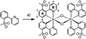
Dimers [Ir(1)2Cl]2 and [Ir(2)2Cl]2 were prepared from [Ir(cod)Cl]2 and the corresponding cyclometallating ligand under reflux conditions and their synthesis and characterization have been reported previously.22,23For [Ir(3)2Cl]2, however, the microwave-assisted reaction of IrCl3·xH2O and H3 in a mixture of 2-ethoxyethanol and water proved to be more successful (Scheme 2). The dimer was isolated as an orange solid by filtration and proved to be sufficiently pure for subsequent reactions, as determined by 1H NMR spectroscopy.
[Ir(3)2Cl]2 was characterized by 1H NMR and IR spectroscopy and elemental analysis. The base peak at m/z 657.1 in the LC-ESI mass spectrum of a methanolic solution of [Ir(3)2Cl]2 corresponds to the [Ir(3)2]+ ion. Further peaks at m/z 698.1 and 739.0 were assigned to [Ir(3)2(MeCN)]+ and [Ir(3)2(MeCN)2]+, respectively. The acetonitrile originates from the eluent of the LC column; this has already been observed for analogous dimers.22
Synthesis and characterization of [Ir(C^N)2(bpy)][PF6] complexes
The synthesis and characterization of [Ir(1)2(bpy)][PF6] have been reported previously.22 The complexes [Ir(2)2(bpy)][PF6] and [Ir(3)2(bpy)][PF6] were prepared in a similar manner by reactions of [Ir2(2)4Cl2] or [Ir2(3)4Cl2] with 2,2′-bipyridine in MeOH in a microwave reactor (Scheme 3).20 Counterion exchange with NH4PF6 yielded [Ir(2)2(bpy)][PF6] and [Ir(3)2(bpy)][PF6] as yellow solids in moderate yields. The products were characterized by 1H and 13C NMR spectroscopy, electrospray ionization mass spectrometry and elemental analysis.In the ESI mass spectrum of both [Ir(2)2(bpy)][PF6] and [Ir(3)2(bpy)][PF6], the base peak at m/z 813.4 corresponded to the [Ir(C^N)2(bpy)]+ cation with the typical iridium isotope pattern. 1H and 13C NMR signals were assigned using 2D methods (COSY, HMQC and HMBC). In Fig. 1, the 1H NMR spectrum of [Ir(3)2(bpy)][PF6] in CD3CN solution is shown as a representative example.
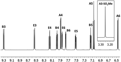 | ||
| Fig. 1 500 MHz 1H NMR spectrum of complex [Ir(3)2(bpy)][PF6] in CD3CN with signal assignments. See Scheme 3 for proton labelling. Scale: δ/ppm. | ||
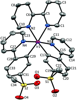
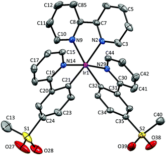
Crystal structures
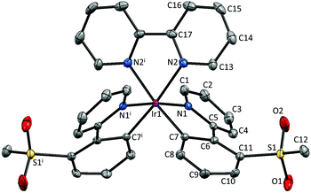
Single crystals of 2{[Ir(1)2(bpy)][PF6]}·7CH2Cl2, 2{[Ir(2)2(bpy)][PF6]}·5.5H2O and [Ir(3)2(bpy)][PF6] were obtained by layering a CH2Cl2 solution with Et2O, an MeCN solution with tert-butyl methyl ether (t-BME) and an MeCN solution with Et2O, respectively. 2{[Ir(1)2(bpy)][PF6]}·7CH2Cl2 crystallizes in the orthorhombic space group Pbca, whereas 4{[Ir(2)2(bpy)][PF6]}·11H2O and [Ir(3)2(bpy)][PF6] crystallize in the monoclinic space groups P21/c and C2/c, respectively. Structures of the complex cations are shown in Fig. 2–4; selected bond lengths and angles are reported in the figure captions.In 2{[Ir(1)2(bpy)][PF6]}·7CH2Cl2, the solvent molecules are heavily disordered and have been modelled over four positions with fractional occupancies. Two independent cations (both are Λ enantiomers) and two ordered [PF6]− (one of half occupancy) are present in the asymmetric unit of 2{[Ir(2)2(bpy)][PF6]}·5.5H2O. In addition, the [PF6]− ion containing atom P88 resides on a special position, leading to the ion being shared equally between two unit cells. The asymmetric unit of [Ir(3)2(bpy)][PF6] contains half a cation and half an anion. The second half is generated by a C2 axis through the central Ir atom, parallel to the b axis of the unit cell.
All the complexes crystallize in achiral space groups, with both enantiomers present in the unit cell.
The bpy ligand is nearly planar in 2{[Ir(1)2(bpy)][PF6]}·7CH2Cl2, with an angle of 3.0° between the pyridyl ring planes. By moving the sulfone group from the 5- to 4-position, the deviation from planarity becomes larger, with angles between the ring planes of 6.4 and 7.8° in the two independent cations in 2{[Ir(2)2(bpy)][PF6]}·5.5H2O. In [Ir(3)2(bpy)][PF6], with the sulfone substituent in the 3-position, the bpy ligand is substantially twisted, with an angle of 13.6° between the pyridine ring planes.
The presence of intramolecular CHaryl⋯OS hydrogen bonds has been observed in a series of alkyl–aryl47 and diaryl sulfones,47,48 as well as in ligand H1,22 dimer [Ir(1)2Cl]2![[thin space (1/6-em)]](https://www.rsc.org/images/entities/char_2009.gif) 22 and the related complex [Ir(2)2(dmpzpy)][PF6] (dmpzpy = 2-(3,5-dimethyl-1H-pyrazol-1-yl)pyridine).23 The sulfone groups in the [Ir(1)2(bpy)]+ cation are twisted with respect to the phenyl ring to which they are attached with torsion angles of 14.8° (O3–S2–C31–C30), −34.5° (O4–S2–C31–C32), 20.8° (O1–S1–C19–C18) and −30.2° (O2–S1–C19–C20). This leads to an optimization of intramolecular CH⋯O contacts in the range 2.55–2.70 Å. In [Ir(2)2(bpy)]+, a similar arrangement of the sulfone groups is observed, leading to CH⋯O contacts ranging from 2.50 to 2.80 Å. In contrast, in [Ir(3)2(bpy)]+, steric hindrance leads to a different orientation of the SO2Me group, resulting in interactions between the O atoms of the sulfone group and the adjacent pyridyl ring, with distances of 2.49 Å (O1⋯HC4) and 2.77 Å (O2⋯HC4). Due to the steric hindrance, the ppy cyclometallating ligand is severely distorted, giving rise to an angle of 22.2° between the ring planes. In both [Ir(1)2(bpy)]+ and [Ir(2)2(bpy)]+, no such strong deviation from planarity is observed and the corresponding angles lie in the range 2.0–6.2°.
22 and the related complex [Ir(2)2(dmpzpy)][PF6] (dmpzpy = 2-(3,5-dimethyl-1H-pyrazol-1-yl)pyridine).23 The sulfone groups in the [Ir(1)2(bpy)]+ cation are twisted with respect to the phenyl ring to which they are attached with torsion angles of 14.8° (O3–S2–C31–C30), −34.5° (O4–S2–C31–C32), 20.8° (O1–S1–C19–C18) and −30.2° (O2–S1–C19–C20). This leads to an optimization of intramolecular CH⋯O contacts in the range 2.55–2.70 Å. In [Ir(2)2(bpy)]+, a similar arrangement of the sulfone groups is observed, leading to CH⋯O contacts ranging from 2.50 to 2.80 Å. In contrast, in [Ir(3)2(bpy)]+, steric hindrance leads to a different orientation of the SO2Me group, resulting in interactions between the O atoms of the sulfone group and the adjacent pyridyl ring, with distances of 2.49 Å (O1⋯HC4) and 2.77 Å (O2⋯HC4). Due to the steric hindrance, the ppy cyclometallating ligand is severely distorted, giving rise to an angle of 22.2° between the ring planes. In both [Ir(1)2(bpy)]+ and [Ir(2)2(bpy)]+, no such strong deviation from planarity is observed and the corresponding angles lie in the range 2.0–6.2°.
Photophysical properties
UV/Vis absorption spectra of the complexes [Ir(C^N)2(bpy)][PF6] with C^N = [1]− to [3]− in MeCN solution are shown in Fig. 5. All the compounds have relatively similar absorption spectra with maxima in the UV region, between 250 and 260 nm. The bands in the UV region are intense and can be assigned to spin-allowed π → π* transitions centred on the ligands. The less intense bands at higher wavelengths up to 450 nm correspond to metal-to-ligand (1MLCT) and ligand-to-ligand charge transfer (1LLCT) transitions.3 The lowest-energy tails of the absorption spectrum of [Ir(3)2(bpy)][PF6] extend more in the visible than those of [Ir(1)2(bpy)][PF6], and these more than those of [Ir(2)2(bpy)][PF6] (Fig. 5).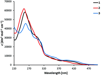 | ||
| Fig. 5 Absorption spectra of 1 × 10⁻⁵ M MeCN solutions of complexes [Ir(C^N)2(bpy)][PF6] with C^N = [1]− to [3]−. | ||
Photoluminescence spectra shown in Fig. 6 were obtained by excitation of MeCN solutions of compounds [Ir(C^N)2(bpy)][PF6] (C^N = [1]− to [3]−). The emission profiles are independent of the excitation wavelength. Emission occurs from the lowest-lying triplet state (T1), which consists of contributions from charge transfer (3MLCT and 3LLCT) and ligand-centred (3LC) triplet states in complexes of the type [Ir(C^N)2(N^N)]+.3 While [Ir(2)2(bpy)][PF6] has a broad and unstructured emission profile, indicating a higher charge transfer character, both [Ir(1)2(bpy)][PF6] and [Ir(3)2(bpy)][PF6] show vibrational structures in their emission profiles, indicating larger 3LC character of the emissive state. This assumption is further supported by the radiative decay rate constants (kr = PLQY/τ) of the compounds (Table 1). In general, the higher the rate constant, the smaller the contribution of the 3LC state to the emissive triplet state.3 In this series of complexes, [Ir(2)2(bpy)][PF6] has a kr (7.2 × 10⁵ s−1) more than double that of the other two complexes (3.2 and 2.6 × 10⁵ s−1). This observation is therefore in accordance with the supposed higher charge transfer character of the emissive state of [Ir(2)2(bpy)][PF6] when compared to complexes [Ir(1)2(bpy)][PF6] and [Ir(3)2(bpy)][PF6].
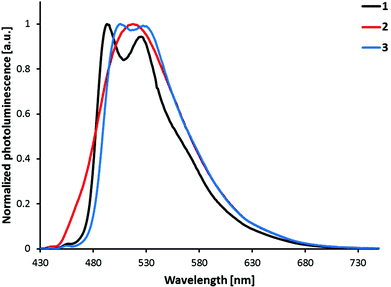 | ||
| Fig. 6 Photoluminescence spectra of complexes [Ir(C^N)2(bpy)][PF6] (C^N = [1]− to [3]−), 1 × 10⁻⁵ M in MeCN solution. Excitation wavelength: 400 nm. | ||
| Complex | MeCN solution | Powder samples | |||||||
|---|---|---|---|---|---|---|---|---|---|
λ
maxem![[thin space (1/6-em)]](https://www.rsc.org/images/entities/char_2009.gif) a [nm] a [nm] |
τ
1/2![[thin space (1/6-em)]](https://www.rsc.org/images/entities/char_2009.gif) b [μs] b [μs] |
PLQYa [%] | k r [105 s−1] | k nr [105 s−1] |
λ
maxem![[thin space (1/6-em)]](https://www.rsc.org/images/entities/char_2009.gif) c [nm] c [nm] |
τ
av![[thin space (1/6-em)]](https://www.rsc.org/images/entities/char_2009.gif) b,d [μs] b,d [μs] |
τ 1 [μs] (A1), τ2 [μs] (A2)b,d | PLQYa [%] | |
| a λ exc = 262 nm for [Ir(1)2(bpy)][PF6], 271 nm for [Ir(2)2(bpy)][PF6] and 261 nm for [Ir(3)2(bpy)][PF6]. b λ exc = 280 nm. c λ exc = 340 nm. d Biexponential fit using the equation τav = ∑Aiτi/∑Ai where Ai is the pre-exponential factor of the lifetime. | |||||||||
| [Ir(1)2(bpy)][PF6] | 493, 525 | 2.33 | 74 | 3.2 | 1.1 | 535 | 0.475 | 0.299 (7035), 1.01 (691) | 6.6 |
| [Ir(2)2(bpy)][PF6] | 517 | 1.28 | 92 | 7.2 | 0.63 | 542 | 1.19 | 0.456 (2233), 1.58 (1201) | 27 |
| [Ir(3)2(bpy)][PF6] | 506, 527 | 2.97 | 77 | 2.6 | 0.77 | 542 | 0.663 | 0.306 (4221), 1.41 (439) | 6.1 |
All three complexes are green emitters in solution (Fig. 7) and their emission maxima are blue-shifted by 68 to 92 nm when compared to the non-substituted parent complex [Ir(ppy)2(bpy)]+ (585 nm).24 Looking at the substitution position of the sulfonyl group, complex [Ir(1)2(bpy)][PF6] shows the largest blue-shift of the emission maximum, while [Ir(2)2(bpy)][PF6] has the smallest. The influence of the sulfone position on the emission maximum therefore follows the trend: 5-position > 3-position > 4-position. However, the different shapes of the emission bands, namely the broad emission of [Ir(2)2(bpy)][PF6] with just one maximum, make comparison difficult. In fact, when comparing the emission spectra of [Ir(2)2(bpy)][PF6] and [Ir(3)2(bpy)][PF6] (Fig. 6), the bands look very similar, with λmaxem of [Ir(2)2(bpy)][PF6] (517 nm) approximately in the middle of the two maxima of [Ir(3)2(bpy)][PF6] (506, 527 nm). The emission maxima of [Ir(1)2(bpy)][PF6] (493, 525 nm) are definitely shifted to the blue; however, the emission band of [Ir(2)2(bpy)][PF6] extends further into the high energy region than those of the other two complexes.
 | ||
| Fig. 7 Photographs of complexes [Ir(C^N)2(bpy)][PF6] with C^N = [1]− to [3]− under 366 nm light excitation: (a) in MeCN, (b) as powder samples. | ||
Most of the regioisomeric iridium complexes investigated so far have shown that a substituent in the 4-position has the largest influence on the emission colour. The largest blue-shift has been observed on introducing an electron-withdrawing group in the 4-position15,26,28,30,33 and the largest red-shift on the introduction of an electron-donating substituent in the 4-position.25,27 However, Bronstein et al. have reported a different trend in the emission maximum of their bromo- and fluorenyl-substituted isomers.31 For both series, they showed that the largest influence was exerted by a substituent in the 5-position of the phenyl ring. This observation is in accordance with the trend in emission maxima in the present series of regioisomeric complexes. Concerning the nature of the triplet emissive state, the present data can be compared with a series of SF5-functionalized [Ir(C^N)2(N^N)]+ complexes.33 In both series, moving the substituent in the phenyl ring of the C^N ligand from the 5- to 4-position (meta to para to the Ir–C bond) leads to a decrease in 3LC and an increase in the CT character of the emissive state, observed by a broadening of the emission spectrum and a shorter excited-state lifetime. Replacement of the bpy ancillary ligand by pyrazolylpyridines in combination with the 4- and 5-substituted sulfonyl cyclometallating ligands gives a different trend, with the para-substituted complexes resulting in the largest blue-shift in the emission maximum.23 This observation can be explained by a change in the nature of the emissive state, from a larger charge transfer (bpy) to a more ligand-centred character (pzpy), causing a structured emission band and a 54 nm blue-shift. The emission colour is therefore strongly dependent on both cyclometallating and ancillary ligands, making the comparison within the herein presented series difficult due to different contributions of ligand-centred and charge transfer states to the triplet emissive state.
Photoluminescence quantum yields (PLQY, Table 1) of complexes [Ir(C^N)2(bpy)][PF6] with C^N = [1]− to [3]− were measured in de-aerated MeCN solution and are relatively high with values between 74 and 92%. While [Ir(1)2(bpy)][PF6] (74%) and [Ir(3)2(bpy)][PF6] (77%) have similar quantum yields, the PLQY of [Ir(2)2(bpy)][PF6] (92%) is significantly higher. Such a trend has also been described by Bronstein et al.;31 in their series, they observed the highest quantum yield for the complex with a substituent in the 4-position of the cyclometallating ligand. When solutions of compounds [Ir(C^N)2(bpy)][PF6] (C^N = [1]− to [3]−) are not de-aerated, PLQYs are much lower (between 4.5 and 7.0%), indicating strong oxygen quenching.
Excited-state lifetimes in de-aerated MeCN solutions under an argon atmosphere are of the order of a few microseconds, ranging from 1.28 μs for [Ir(2)2(bpy)][PF6] to 2.97 μs for [Ir(3)2(bpy)][PF6] (Table 1). Again, much shorter excited state lifetimes are observed for the non-de-aerated solutions (0.144 to 0.310 μs), which can be attributed to quenching due to oxygen present in the system.
The photoluminescence spectra shown in Fig. 8 are obtained by the excitation of powder samples of complexes [Ir(C^N)2(bpy)][PF6] with C^N = [1]− to [3]−. The vibrational structure observed in the solution spectra of [Ir(1)2(bpy)][PF6] and [Ir(3)2(bpy)][PF6] is almost completely lost in the solid state spectra. For all the complexes, powder emission is red-shifted compared to solution emission (Fig. 7). The largest red-shift is observed for [Ir(1)2(bpy)][PF6] (42 nm), and the smallest for [Ir(2)2(bpy)][PF6] (25 nm). In powder samples, the difference between the emission maxima of the complexes is smaller (7 nm) than that in solution (24 nm).
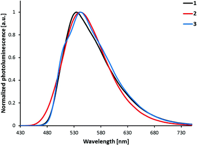 | ||
| Fig. 8 Photoluminescence spectra of complexes [Ir(C^N)2(bpy)][PF6] (C^N = [1]− to [3]−) in the solid state (powder). Excitation wavelength: 340 nm. | ||
PLQYs of powder samples are significantly lower than solution quantum yields, ranging from 6–7% for [Ir(1)2(bpy)][PF6] and [Ir(3)2(bpy)][PF6] to 27% for [Ir(2)2(bpy)][PF6] (Table 1). As for solution PLQYs, [Ir(2)2(bpy)][PF6] has the highest quantum yield. Excited-state lifetimes in powder samples are shorter than those in solution (Table 1); biexponential fits were used for τ of all three complexes. Shorter lifetimes, lower quantum yields and less vibrational structure indicate strong luminescence quenching in the solid state due to intermolecular interactions.11
The photoluminescence properties in the amorphous thin film configuration used in LEC devices, where the complex is mixed with the ionic liquid (IL) 1-butyl-3-methylimidazolium hexafluoridophosphate [Bmim][PF6] in a complex![[thin space (1/6-em)]](https://www.rsc.org/images/entities/char_2009.gif) :
:![[thin space (1/6-em)]](https://www.rsc.org/images/entities/char_2009.gif) IL 4
IL 4![[thin space (1/6-em)]](https://www.rsc.org/images/entities/char_2009.gif) :
:![[thin space (1/6-em)]](https://www.rsc.org/images/entities/char_2009.gif) 1 molar ratio, were also investigated (Fig. S1†). The band maximum is positioned at 533 nm for [Ir(1)2(bpy)][PF6], 548 nm for [Ir(2)2(bpy)][PF6] and 539 nm for [Ir(3)2(bpy)][PF6]. These values are very similar to those observed in powder. However, the photoluminescence intensity is enhanced in the amorphous environment. Whereas the PLQYs of [Ir(1)2(bpy)][PF6] and [Ir(3)2(bpy)][PF6] are in the range 11–13%, [Ir(2)2(bpy)][PF6] shows a significantly larger PLQY of 45%. These values double the intensity of the photoluminescence emission recorded in powder, which indicates a strong decrease of the luminescence quenching due to the presence of the ionic liquid that decreases the intermolecular interactions between the complexes.
1 molar ratio, were also investigated (Fig. S1†). The band maximum is positioned at 533 nm for [Ir(1)2(bpy)][PF6], 548 nm for [Ir(2)2(bpy)][PF6] and 539 nm for [Ir(3)2(bpy)][PF6]. These values are very similar to those observed in powder. However, the photoluminescence intensity is enhanced in the amorphous environment. Whereas the PLQYs of [Ir(1)2(bpy)][PF6] and [Ir(3)2(bpy)][PF6] are in the range 11–13%, [Ir(2)2(bpy)][PF6] shows a significantly larger PLQY of 45%. These values double the intensity of the photoluminescence emission recorded in powder, which indicates a strong decrease of the luminescence quenching due to the presence of the ionic liquid that decreases the intermolecular interactions between the complexes.
Electrochemical properties
Cyclic voltammetric data in MeCN solution of compounds [Ir(C^N)2(bpy)][PF6] with C^N = [1]− to [3]− are summarized in Table 2 and cyclic voltammograms are shown in Fig. S2.† In complexes of the type [Ir(C^N)2(N^N)][PF6], the first reduction is based on the N^N ligand, while the first oxidation is metal-based with a contribution from the C^N ligands.32 In our series, the first reduction waves are reversible and the potentials are similar, ranging from −1.67 to −1.72 V (with respect to Fc/Fc+). As all three complexes have the same N^N ligand (bpy), this result was expected and is comparable to the reduction potential of [Ir(ppy)2(bpy)][PF6] (−1.77 V, in DMF).24 Two to four more reduction waves have been observed for compounds [Ir(C^N)2(bpy)][PF6] (C^N = [1]− to [3]−), but were not investigated in detail. A larger influence on the oxidation depending on the substitution position of the sulfone group on the cyclometallating ligand was anticipated and has been observed in our case. Oxidation processes are reversible or quasi-reversible and occur at +1.18, +1.20 and +1.29 V for [Ir(C^N)2(bpy)][PF6] with C^N = [1]−, [3]− and [2]−, respectively. The largest stabilization of the HOMO and the largest influence on the oxidation process are therefore observed for [Ir(2)2(bpy)][PF6] with the sulfone substituent in the 4-position. Compared to [Ir(ppy)2(bpy)][PF6] (+0.84 V),24 the oxidation waves of all three complexes [Ir(C^N)2(bpy)][PF6] (C^N = [1]− to [3]−) are shifted to more positive potential, consistent with the blue-shift in the emission maximum.| Complex | E ox1/2 [V] | E red1/2 [V] | ΔE1/2 [V] |
|---|---|---|---|
| [Ir(1)2(bpy)][PF6] | +1.18 | −1.72, −2.16, −2.61ir | 2.90 |
| [Ir(2)2(bpy)][PF6] | +1.29 | −1.67, −2.27qr, −2.52qr | 2.96 |
| [Ir(3)2(bpy)][PF6] | +1.20qr | −1.69, −2.06ir, −2.16ir, −2.34ir, −2.52ir | 2.89 |
Theoretical calculations
To gain a deeper insight into the electrochemical and photophysical properties of complexes [Ir(C^N)2(bpy)][PF6] (C^N = [1]− to [3]−), a combined DFT/TD-DFT theoretical investigation of their respective cations was undertaken at the B3LYP/(6-31G** + LANL2DZ) level in the presence of the solvent (acetonitrile) (see the Experimental section for full computational details).The geometry of the complexes in their ground electronic state (S0) was fully optimized without imposing any symmetry restriction. The calculations reproduce the main trends observed in the experiments. They predict a near octahedral coordination of the Ir metal where the ancillary bpy ligands remain mostly planar, with N–C–C–N dihedral angles of 3.2, 3.5 and 2.8°. In accord with the X-ray structures, the ppy cyclometallating ligands deviate from planarity in passing from [Ir(1)2(bpy)]+ and [Ir(2)2(bpy)]+ (inter-ring angle of 0.8–0.9°) to [Ir(3)2(bpy)]+ for which the ring planes form an angle of 12.8°. In [Ir(1)2(bpy)]+ and [Ir(2)2(bpy)]+, the SO2Me groups adopt a conformation in which the methyl is perpendicular to the phenyl ring and the oxygen atoms form CH⋯O contacts of about 2.60 Å. In [Ir(3)2(bpy)]+ the SO2Me groups form closer CH⋯O contacts of 2.02 and 2.22 Å with adjacent pyridyl and phenyl rings, respectively.
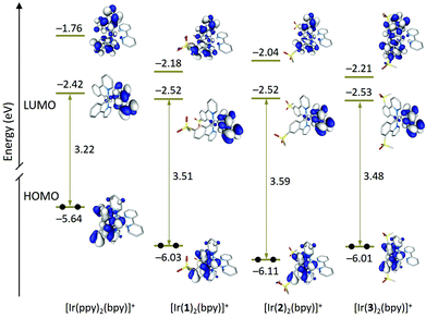
Fig. 9 shows the energy and electron density contours calculated for the highest-occupied (HOMO) and lowest-unoccupied molecular orbitals (LUMO and LUMO+1) of [Ir(1)2(bpy)]+, [Ir(2)2(bpy)]+ and [Ir(3)2(bpy)]+, which are compared with those obtained for the archetypal complex [Ir(ppy)2(bpy)]+. The topology of the MOs is the same for all three complexes and reproduce that of the MOs of the reference complex [Ir(ppy)2(bpy)]+. The LUMO+2, which is not displayed in Fig. 9, is close in energy to the LUMO+1 and shows a similar topology.
The introduction of the sulfone groups stabilizes the HOMO by 0.4–0.5 eV because, as expected, this orbital is located on the Ir atom and the phenyl rings of the C^N ligands to which the electron-withdrawing SO2Me groups are attached (Fig. 9). Calculations confirm the larger stabilization of the HOMO by ∼0.1 eV for complex [Ir(2)2(bpy)]+ in good agreement with the higher oxidation potential measured for [Ir(2)2(bpy)]+ (1.29 V) when compared with [Ir(1)2(bpy)]+ (1.18 V) and [Ir(3)2(bpy)]+ (1.20 V). The stabilization is larger for [Ir(2)2(bpy)]+ because the carbon in the 4-position, to which the SO2Me group is linked, contributes to the HOMO to a higher degree than the carbons in 5- and 3-positions. This enhances the electron-withdrawing effect of the sulfone groups compared with [Ir(1)2(bpy)]+ and [Ir(3)2(bpy)]+. A similar result was observed when changing the sulfone position from 5 to 4 in a closely related family of complexes with pyrazolylpyridine N^N ligands.23
Regarding the unoccupied MOs, the introduction of the sulfone groups especially stabilizes the orbitals localized on the C^N ligands. In this way, the LUMO+1 of [Ir(ppy)2(bpy)]+ (−1.76 eV) decreases in energy by 0.42 and 0.45 eV in passing to [Ir(1)2(bpy)]+ and [Ir(3)2(bpy)]+, respectively. The stabilization is smaller for [Ir(2)2(bpy)]+ (0.28 eV) because of the minor participation of the carbon in the 4-position to which the sulfone group is attached. Similar trends are found for LUMO+2, the partner of LUMO+1 also located on the C^N ligands. The LUMO, which is mainly concentrated on the bpy ligand, undergoes a smaller stabilization of about 0.10 eV for all three complexes (Fig. 9). The energies predicted for the LUMO are in good agreement with similar values recorded for the first reduction potential of [Ir(C^N)2(bpy)][PF6] (C^N = [1]− to [3]−) that are ∼0.10 V less negative than that reported for [Ir(ppy)2(bpy)]+ (−1.77 V) (Table 2).3
The higher HOMO–LUMO gap predicted for [Ir(2)2(bpy)]+ (3.59 eV) compared with [Ir(1)2(bpy)]+ (3.51 eV) and [Ir(2)2(bpy)]+ (3.48 eV) is in accord with the blue shift observed for the lowest energy band of [Ir(2)2(bpy)]+ in the absorption spectrum (Fig. 5). This band is actually due to a set of electronic transitions involving singlet excited states of 3MLCT/3LLCT nature calculated at ∼350 nm, but also to the lower-energy 3LC states located on the sulfone-substituted ppy ligands (Table S1†). The theoretical simulation obtained from the TD-DFT calculation of the singlet excited states (Fig. S6†) correctly predicts the shape of the experimental absorption spectra (Fig. 5).
To investigate the nature of the lowest-energy triplet excited states, a TD-DFT study was first performed for [Ir(C^N)2(bpy)]+ (C^N = [1]− to [3]−) at the optimized geometry of S0. Table 3 compares the excitation energies and electronic nature computed for the three lowest triplet states and includes those obtained for the reference complex [Ir(ppy)2(bpy)]+. The nature of the three triplets is the same for all four complexes but the energy ordering changes. For [Ir(ppy)2(bpy)]+, the lowest lying triplet (T1) results from the HOMO → LUMO excitation and therefore implies a charge transfer from the metal and the phenyl rings of the cyclometallating ligands, where the HOMO is located, to the ancillary ligand, where the LUMO resides (see Fig. 9). The T1 state therefore shows a mixed 3MLCT/3LLCT character. The T2 and T3 triplets are well above T1 by ∼0.3 eV and mainly imply excitations from the HOMO to the LUMO+1 and LUMO+2 located on the cyclometallating ppy− ligands. T2 and T3 therefore correspond to 3LC states with some contribution from the metal.
| Complex | State | E (eV)/λ (nm) | Monoexcitations | Description |
|---|---|---|---|---|
| [Ir(ppy)2(bpy)]+ | T1 | 2.50/496 | H → L (98) | 3MLCT/3LLCT |
| T2 | 2.77/448 | H → L+1 (66) | 3LC | |
| T3 | 2.81/441 | H → L+2 (54) | 3LC | |
| H–1 → L+1 (26) | 3LC | |||
| [Ir(1)2(bpy)]+ | T1 | 2.71/457 | H → L+1 (70) | 3LC |
| T2 | 2.76/448 | H → L+2 (60) | 3LC | |
| T3 | 2.77/447 | H → L (94) | 3MLCT/3LLCT | |
| [Ir(2)2(bpy)]+ | T1 | 2.85/435 | H → L (89) | 3MLCT/3LLCT |
| T2 | 2.87/432 | H → L+1 (57) | 3LC | |
| T3 | 2.91/426 | H → L+2 (44) | 3LC | |
| H–1 → L+1 (29) | 3LC | |||
| [Ir(3)2(bpy)]+ | T1 | 2.67/464 | H → L+1 (59) | 3LC |
| T2 | 2.72/456 | H → L+2 (66) | 3LC | |
| T3 | 2.76/449 | H → L (77) | 3MLCT/3LLCT |
Compared with [Ir(ppy)2(bpy)]+, the energy ordering and electronic nature of the T1 to T3 triplets remain the same for [Ir(2)2(bpy)]+ but are reversed for [Ir(1)2(bpy)]+ and [Ir(3)2(bpy)]+ (Table 3). For the latter, T1 and T2 now correspond to the 3LC states and T3 is the HOMO → LUMO 3MLCT/3LLCT state. The three states are indeed very close in energy (0.06–0.09 eV) for all three complexes. The energy collapse of the three states is due to the larger stabilization of the MOs located on the C^N ligands induced by the sulfone substituents (Fig. 9). As a result, the LUMO+1 and LUMO+2 come closer to the LUMO in [Ir(C^N)2(bpy)]+ (C^N = [1]− to [3]−) than they are in [Ir(ppy)2(bpy)]+, and the T1 to T3 states become almost degenerate for the former. The HOMO → LUMO+1, LUMO+2 3LC triplets are slightly less stable for [Ir(2)2(bpy)]+ due to the higher stabilization of the HOMO and the lower stabilization of the LUMO+1 (Fig. 9). This combined effect determines that the HOMO–LUMO+1 gap is larger for [Ir(2)2(bpy)]+ (4.07 eV) than for [Ir(1)2(bpy)]+ (3.85 eV) and [Ir(3)2(bpy)]+ (3.80 eV) and, as a consequence, the T1 state preserves the HOMO → LUMO 3MLCT/3LLCT nature for [Ir(2)2(bpy)]+.
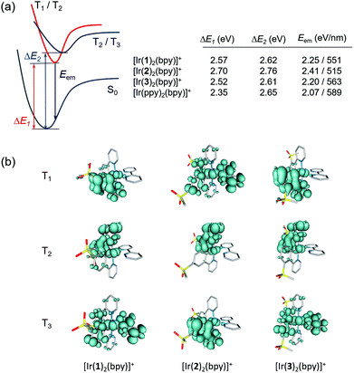
To verify the predicted trends and to obtain additional information about the emitting state, the geometries of the lowest triplet excited states of [Ir(C^N)2(bpy)]+ (C^N = [1]− to [3]−) and [Ir(ppy)2(bpy)]+ were optimized using the spin-unrestricted UB3LYP approach. In all cases, we were able to locate the minimum energy geometries of the three lowest triplet states by carefully selecting the starting point for the optimization process. Fig. 10a summarizes the adiabatic energy difference (ΔE), calculated as the difference between the total energies of S0 and T1, T2 or T3 at their respective minimum-energy structures, and the emission energy (Eem), estimated as the vertical energy difference between T1 and S0 at the optimized minimum-energy geometry of T1. Fig. 10b shows the unpaired-electron spin density distributions calculated for T1 to T3 at their optimized geometries.
The T1 and T2 states of [Ir(1)2(bpy)]+ and [Ir(3)2(bpy)]+ become degenerate upon full-geometry relaxation and present a spin-density distribution mainly centred on one of the cyclometallating ligands (∼1.7 unpaired electrons) with a small contribution from the metal (∼0.3e) (Fig. 10b). In contrast, T3 features a spin density distribution spreading the ppy-Ir environment and the bpy ligand (Ir ∼ 0.5e, C^N ligands ∼ 0.5e, N^N ligand ∼ 1.0e) that perfectly matches the topology of the HOMO → LUMO MLCT/LLCT excitation. Calculations therefore confirm the predominant 3LC nature of the lowest-energy triplet state of [Ir(1)2(bpy)]+ and [Ir(3)2(bpy)]+ in accord with the structured shape of the emission band observed experimentally for these two complexes (Fig. 6).
The T1 to T3 states of [Ir(2)2(bpy)]+ appear at higher energies (Fig. 10a), and their spin-density distributions are reversed with respect to those computed for [Ir(1)2(bpy)]+ and [Ir(3)2(bpy)]+ (Fig. 10b). Now, the T1 triplet corresponds to the 3MLCT/3LLCT state whereas T2 and T3 are of 3LC nature. The 3MLCT/3LLCT nature predicted for the lowest-energy triplet is in good agreement with the structureless shape of the emission band registered experimentally for [Ir(2)2(bpy)]+ (Fig. 6). Calculations therefore support the change in the electronic nature of the emitting state from 3LC to 3MLCT/3LLCT in passing from the [Ir(1)2(bpy)]+ and [Ir(3)2(bpy)]+ complexes to [Ir(2)2(bpy)]+. The change is due to the different effect the electron-withdrawing sulfone groups have on the energies of the frontier molecular orbitals depending on the phenyl position of the ppy− ligands to which they are attached. When introduced in the 4-position, as in [Ir(2)2(bpy)]+, they have a larger stabilization effect on the HOMO and a lower stabilization effect on the LUMO+1 and LUMO+2, and this determines that the emitting triplet corresponds to the HOMO → LUMO 3MLCT/3LLCT state as in the reference complex [Ir(ppy)2(bpy)]+. The emission wavelength predicted for [Ir(2)2(bpy)]+ (515 nm) is in good agreement with the λmaxem measured experimentally in MeCN solution (517 nm).
Electroluminescence
The electroluminescent behaviour of complexes [Ir(C^N)2(bpy)][PF6] (C^N = [1]− to [3]−) was tested by incorporating them into LEC devices. The preparation of the devices consisted in the deposition in air of an 80 nm layer of PEDOT:PSS on top of a patterned indium tin oxide coated glass substrate followed by a 100 nm emitting layer. The emitting layer was prepared by mixing one of the complexes with the ionic liquid [Bmim][PF6] at a molar ratio of 4![[thin space (1/6-em)]](https://www.rsc.org/images/entities/char_2009.gif) :
:![[thin space (1/6-em)]](https://www.rsc.org/images/entities/char_2009.gif) 1. After this, the devices were annealed at 100 °C for one hour under an inert atmosphere and the top aluminium contact was deposited by thermal evaporation.
1. After this, the devices were annealed at 100 °C for one hour under an inert atmosphere and the top aluminium contact was deposited by thermal evaporation.
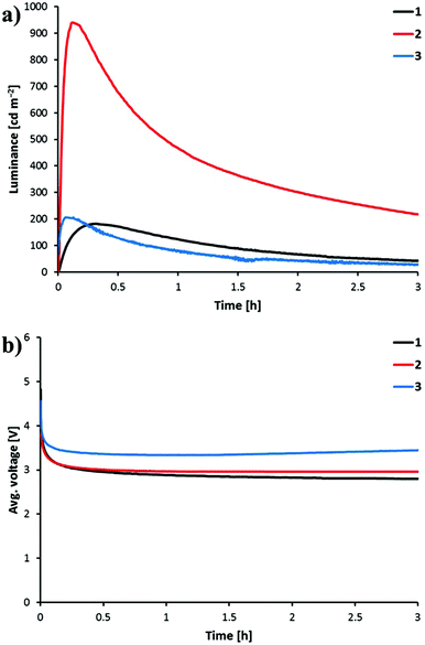
The devices were operated using a block-wave pulsed current driving mode (average current density: 100 A m−2, frequency: 1000 Hz, duty cycle: 50%). This driving method was selected in order to enhance the device response. Under these conditions, the voltage required to maintain the current density decreases versus time due to the formation of p- and n-doped regions, which reduces the resistance of the active layer. The LEC behaviour is depicted in Fig. 11 and the performance parameters are summarized in Table 4. All the LECs prepared show a fast decrease of the voltage accompanied by a fast increase of the luminance. A luminance of 100 cd m−2 (t100) is reached in 14, 32 and 250 s when complexes [Ir(C^N)2(bpy)][PF6] with C^N = [1]−, [2]− and [3]−, respectively, are incorporated into the LEC. Once the maximum luminance (Lummax) is reached, the decay of the luminance leads to short lifetimes (t½) as has been observed for previously reported LECs based on green emitters under the same driving conditions. Faster LEC shows faster decay of luminance and shorter lifetime.20,49 This behaviour can be related with a fast growth of the doped regions, which efficiently quench light-emitting excitons.
![[thin space (1/6-em)]](https://www.rsc.org/images/entities/char_2009.gif) :
:![[thin space (1/6-em)]](https://www.rsc.org/images/entities/char_2009.gif) [Bmim][PF6] 4
[Bmim][PF6] 4![[thin space (1/6-em)]](https://www.rsc.org/images/entities/char_2009.gif) :
:![[thin space (1/6-em)]](https://www.rsc.org/images/entities/char_2009.gif) 1 molar ratio
1 molar ratio
| Complex |
t
100![[thin space (1/6-em)]](https://www.rsc.org/images/entities/char_2009.gif) a [s] a [s] |
Lummax![[thin space (1/6-em)]](https://www.rsc.org/images/entities/char_2009.gif) b [cd m−2] b [cd m−2] |
t
1/2![[thin space (1/6-em)]](https://www.rsc.org/images/entities/char_2009.gif) c [h] c [h] |
Efficacymax![[thin space (1/6-em)]](https://www.rsc.org/images/entities/char_2009.gif) d [cd A−1] d [cd A−1] |
PCEmax![[thin space (1/6-em)]](https://www.rsc.org/images/entities/char_2009.gif) e [lm W−1] e [lm W−1] |
EQEmax![[thin space (1/6-em)]](https://www.rsc.org/images/entities/char_2009.gif) f [%] f [%] |
|---|---|---|---|---|---|---|
| a Time to reach 100 cd m−2. b Maximum luminance. c Time to reach one-half the maximum luminance. d Maximum efficacy. e Maximum power conversion efficiency. f Maximum external quantum efficiency (EQE). | ||||||
| [Ir(1)2(bpy)][PF6] | 250 | 182 | 1.5 | 1.7 | 0.9 | 0.5 |
| [Ir(2)2(bpy)][PF6] | 32 | 940 | 1.0 | 8.8 | 4.5 | 2.6 |
| [Ir(3)2(bpy)][PF6] | 14 | 206 | 0.7 | 1.9 | 0.9 | 0.6 |
Interestingly, the four-times higher PLQY recorded in thin films for [Ir(2)2(bpy)][PF6] (45.0%) compared with [Ir(1)2(bpy)][PF6] (11.6%) and [Ir(3)2(bpy)][PF6] (13.4%) is reflected in the luminance level and the efficiency of the device. The LEC containing [Ir(2)2(bpy)][PF6] reaches a Lummax of 940 cd m−2, whereas LECs incorporating [Ir(1)2(bpy)][PF6] and [Ir(3)2(bpy)][PF6] reach Lummax values close to 200 cd m−2. The higher charge transfer character of the emissive state in complex [Ir(2)2(bpy)][PF6] therefore leads to a much better LEC performance. LECs with [Ir(2)2(bpy)][PF6] show higher efficacy (8.8 cd A−1), power conversion efficiency (PCE = 4.5 lm W−1) and external quantum efficiency (EQE = 2.6%) than those with [Ir(1)2(bpy)][PF6] and [Ir(3)2(bpy)][PF6] (efficacy < 2 cd A−1, PCE < 1 lm W−1 and EQE < 1%) (Table 4). The electroluminescence efficiency obtained for [Ir(2)2(bpy)][PF6] is indeed comparable to that obtained for closely related [Ir(msppz)2(N^N)][PF6] complexes (msppz = 1-[4-(methylsulfonyl)phenyl]-1H-pyrazole) and N^N = bpy-type ligand), which exhibit higher PLQY values in thin films.20 This indicates a better charge-carrier balance in the LECs built with complex [Ir(2)2(bpy)][PF6].
The electroluminescence (EL) spectra recorded for the LECs prepared show emission maxima in the 550–560 nm range for all three complexes (Fig. S7†). The emission band is red-shifted compared with the photoluminescence spectra in solution, powder and thin film, and all the LEC devices exhibit green colour.
Conclusions
Three regioisomeric iridium(III) complexes containing methylsulfonyl-functionalized cyclometallating ligands were prepared to study the effect of the substituent's position on the photophysical, electrochemical and LEC device properties. Structural data for the complexes showed the expected core structures and the influence of the steric hindrance induced by the SO2Me group in the 3-position of the cyclometallating ligand which leads to ligand distortions.The complexes are green emitters in solution and green-yellow emitters as powder samples. Vibrationally structured emission bands were observed in MeCN solution for complexes with sulfone groups in the 3- and 5-position of the phenyl ring (meta to the Ir–C bond). The two complexes showed similar quantum yields and lifetimes. An enhanced PLQY of 92%, a shorter excited-state lifetime and a broad unstructured emission profile were obtained for the 4-substituted compound (substituent para to the Ir–C bond). The lack of a vibrational emission profile suggests a more pronounced charge transfer character of the emissive triplet state compared to the other two complexes. In the solid state (powder), emission maxima are red-shifted, vibrational structure is lost and quantum yields and lifetimes are decreased, indicating excited-state quenching due to intermolecular interactions. The para-substituted complex (4-SO2Me) again exhibits the highest quantum yields of 27% as powder samples and 45% in thin films. Electrochemical data parallel the photoluminescence trends and show that a methylsulfone substituent in the para position to the Ir–C bond has the largest influence on the oxidation potential. DFT calculations rationalize the different effect exerted by the sulfone group depending on the substitution position, and support the experimentally gained results. They confirm the different nature of the emissive triplet state of the meta- (3LC) versus para-substituted (3MLCT/3LLCT) complexes.
Green electroluminescence with maxima ranging from 550 to 560 nm is observed for LECs with all the complexes. Maximum luminance levels, power conversion efficiencies and EQEs are similar for complexes with the sulfone substituent meta to the Ir–C bond. For the complex containing the methylsulfonyl group in the 4-position (para to the Ir–C bond), significantly higher luminance (940 cd m−2) and efficiencies (PCE = 4.4 lm W−1 and EQE = 2.6%) are obtained. The increased efficiency correlates with the higher solid state quantum yield. Lifetimes are rather short and comparable for all the devices, ranging from 0.7 to 1.5 h.
We have shown that while the influence on the emission colour is negligible on changing the substitution position of a sulfone group on the cyclometallating ligand, the nature of the emissive triplet state (ligand-centred or charge transfer) is sensitive to the substitution pattern. This leads to significantly enhanced quantum yields in the case of substitution para to the Ir–C bond and, as a consequence, superior device performance.
Acknowledgements
We thank the Swiss National Science Foundation (grant number 200020_144500), the Spanish Ministry of Economy and Competitiveness (MINECO) of Spain (MAT2014-55200, CTQ2015-71154-P and Unidad de Excelencia María de Maeztu MDM-2015-0552), the European Research Council (Advanced Grant 267816 LiLo) and the University of Basel for financial support.Notes and references
- J. D. Slinker, D. Bernards, P. L. Houston, H. D. Abruña, S. Bernhard and G. G. Malliaras, Chem. Commun., 2003, 2392–2399 RSC.
- J. D. Slinker, J. Rivnay, J. S. Moskowitz, J. B. Parker, S. Bernhard, H. D. Abruña and G. G. Malliaras, J. Mater. Chem., 2007, 17, 2976–2988 RSC.
- R. D. Costa, E. Ortí, H. J. Bolink, F. Monti, G. Accorsi and N. Armaroli, Angew. Chem., Int. Ed., 2012, 51, 8178–8211 CrossRef CAS PubMed.
- T. Hu, L. He, L. Duan and Y. Qiu, J. Mater. Chem., 2012, 22, 4206–4215 RSC.
- R. D. Costa, F. Monti, G. Accorsi, A. Barbieri, H. J. Bolink, E. Ortí and N. Armaroli, Inorg. Chem., 2011, 50, 7229–7238 CrossRef CAS PubMed.
- R. D. Costa, E. Ortí, H. J. Bolink, S. Graber, S. Schaffner, M. Neuburger, C. E. Housecroft and E. C. Constable, Adv. Funct. Mater., 2009, 19, 3456–3463 CrossRef CAS.
- P. Pla, J. M. Junquera-Hernández, H. J. Bolink and E. Ortí, Dalton Trans., 2015, 44, 8497–8505 RSC.
- M. S. Lowry and S. Bernhard, Chem. – Eur. J., 2006, 12, 7970–7977 CrossRef CAS PubMed.
- E. Baranoff, H. J. Bolink, E. C. Constable, M. Delgado, D. Häussinger, C. E. Housecroft, M. K. Nazeeruddin, M. Neuburger, E. Ortí, G. E. Schneider, D. Tordera, R. M. Walliser and J. A. Zampese, Dalton Trans., 2013, 42, 1073–1087 RSC.
- F. De Angelis, S. Fantacci, N. Evans, C. Klein, S. M. Zakeeruddin, J.-E. Moser, K. Kalyanasundaram, H. J. Bolink, M. Grätzel and M. K. Nazeeruddin, Inorg. Chem., 2007, 46, 5989–6001 CrossRef CAS PubMed.
- L. He, L. Duan, J. Qiao, R. Wang, P. Wei, L. Wang and Y. Qiu, Adv. Funct. Mater., 2008, 18, 2123–2131 CrossRef CAS.
- H. J. Bolink, E. Coronado, R. D. Costa, N. Lardiés and E. Ortí, Inorg. Chem., 2008, 47, 9149–9151 CrossRef CAS PubMed.
- M. Tavasli, S. Bettington, I. F. Perepichka, A. S. Batsanov, M. R. Bryce, C. Rothe and A. P. Monkman, Eur. J. Inorg. Chem., 2007, 4808–4814 CrossRef CAS.
- G. Zhou, C.-L. Ho, W.-Y. Wong, Q. Wang, D. Ma, L. Wang, Z. Lin, T. B. Marder and A. Beeby, Adv. Funct. Mater., 2008, 18, 499–511 CrossRef CAS.
- R. Ragni, E. Orselli, G. S. Kottas, O. H. Omar, F. Babudri, A. Pedone, F. Naso, G. M. Farinola and L. De Cola, Chem. – Eur. J., 2009, 15, 136–148 CrossRef CAS PubMed.
- G. Zhou, X. Yang, W.-Y. Wong, Q. Wang, S. Suo, D. Ma, J. Feng and L. Wang, ChemPhysChem, 2011, 12, 2836–2843 CrossRef CAS PubMed.
- Y. Hisamatsu and S. Aoki, Eur. J. Inorg. Chem., 2011, 5360–5369 CrossRef CAS.
- C. Fan, Y. Li, C. Yang, H. Wu, J. Qin and Y. Cao, Chem. Mater., 2012, 24, 4581–4587 CrossRef CAS.
- X. Xu, X. Yang, J. Dang, G. Zhou, Y. Wu, H. Li and W.-Y. Wong, Chem. Commun., 2014, 50, 2473–2476 RSC.
- D. Tordera, A. M. Bünzli, A. Pertegás, J. M. Junquera-Hernández, E. C. Constable, J. A. Zampese, C. E. Housecroft, E. Ortí and H. J. Bolink, Chem. – Eur. J., 2013, 19, 8597–8609 CrossRef CAS PubMed.
- G. E. Schneider, H. J. Bolink, E. C. Constable, C. D. Ertl, C. E. Housecroft, A. Pertegàs, J. A. Zampese, A. Kanitz, F. Kessler and S. B. Meier, Dalton Trans., 2014, 43, 1961–1964 RSC.
- E. C. Constable, C. D. Ertl, C. E. Housecroft and J. A. Zampese, Dalton Trans., 2014, 43, 5343–5356 RSC.
- C. D. Ertl, J. Cerdá, J. M. Junquera-Hernández, A. Pertegás, H. J. Bolink, E. C. Constable, M. Neuburger, E. Ortí and C. E. Housecroft, RSC Adv., 2015, 5, 42815–42827 RSC.
- R. D. Costa, E. Ortí, D. Tordera, A. Pertegás, H. J. Bolink, S. Graber, C. E. Housecroft, L. Sachno, M. Neuburger and E. C. Constable, Adv. Energy Mater., 2011, 1, 282–290 CrossRef CAS.
- J. Nishida, H. Echizen, T. Iwata and Y. Yamashita, Chem. Lett., 2005, 34, 1378–1379 CrossRef CAS.
- V. V. Grushin, N. Herron, D. D. LeCloux, W. J. Marshall, V. A. Petrov and Y. Wang, Chem. Commun., 2001, 1494–1495 RSC.
- T.-H. Kwon, H. S. Cho, M. K. Kim, J.-W. Kim, J.-J. Kim, K. H. Lee, S. J. Park, I.-S. Shin, H. Kim, D. M. Shin, Y. K. Chung and J.-I. Hong, Organometallics, 2005, 24, 1578–1585 CrossRef CAS.
- Q.-L. Xu, C.-C. Wang, T.-Y. Li, M.-Y. Teng, S. Zhang, Y.-M. Jing, X. Yang, W.-N. Li, C. Lin, Y.-X. Zheng, J.-L. Zuo and X.-Z. You, Inorg. Chem., 2013, 52, 4916–4925 CrossRef CAS PubMed.
- G. Sarada, J. Yoon, W. Cho, M. Cho, D. W. Cho, S. O. Kang, Y. Nam, J. Y. Lee and S.-H. Jin, J. Mater. Chem. C, 2016, 4, 113–120 RSC.
- B. J. Coe, M. Helliwell, J. Raftery, S. Sánchez, M. K. Peers and N. S. Scrutton, Dalton Trans., 2015, 44, 20392–20405 RSC.
- H. A. Bronstein, C. E. Finlayson, K. R. Kirov, R. H. Friend and C. K. Williams, Organometallics, 2008, 27, 2980–2989 CrossRef CAS.
- D. L. Davies, M. P. Lowe, K. S. Ryder, K. Singh and S. Singh, Dalton Trans., 2011, 40, 1028–1030 RSC.
- N. M. Shavaleev, G. Xie, S. Varghese, D. B. Cordes, A. M. Z. Slawin, C. Momblona, E. Ortí, H. J. Bolink, I. D. W. Samuel and E. Zysman-Colman, Inorg. Chem., 2015, 54, 5907–5914 CrossRef CAS PubMed.
- D. Tordera, J. J. Serrano-Pérez, A. Pertegás, E. Ortí, H. J. Bolink, E. Baranoff, M. K. Nazeeruddin and J. Frey, Chem. Mater., 2013, 25, 3391–3397 CrossRef CAS.
- N. Ishida, T. Moriya, T. Goya and M. Murakami, J. Org. Chem., 2010, 75, 8709–8712 CrossRef CAS PubMed.
- L. Niu, H. Yang, D. Yang and H. Fu, Adv. Synth. Catal., 2012, 354, 2211–2217 CrossRef CAS.
- APEX2, version 2 User Manual, M86-E01078, Bruker Analytical X-ray Systems, Inc., Madison, WI, 2006 Search PubMed.
- P. W. Betteridge, J. P. Carruthers, R. I. Cooper, K. Prout and D. J. Watkin, J. Appl. Crystallogr., 2003, 36, 1487 CrossRef CAS.
- M. J. Frisch, G. W. Trucks, H. B. Schlegel, G. E. Scuseria, M. A. Robb, J. R. Cheeseman, G. Scalmani, V. Barone, B. Mennucci, G. A. Petersson, H. Nakatsuji, M. Caricato, X. Li, H. P. Hratchian, A. F. Izmaylov, J. Bloino, G. Zheng, J. L. Sonnenberg, M. Hada, M. Ehara, K. Toyota, R. Fukuda, J. Hasegawa, M. Ishida, T. Nakajima, Y. Honda, O. Kitao, H. Nakai, T. Vreven, J. A. Montgomery Jr., J. E. Peralta, F. Ogliaro, M. Bearpark, J. J. Heyd, E. Brothers, K. N. Kudin, V. N. Staroverov, R. Kobayashi, J. Normand, K. Raghavachari, A. Rendell, J. C. Burant, S. S. Iyengar, J. Tomasi, M. Cossi, N. Rega, N. J. Millam, M. Klene, J. E. Knox, J. B. Cross, V. Bakken, C. Adamo, J. Jaramillo, R. Gomperts, R. E. Stratmann, O. Yazyev, A. J. Austin, R. Cammi, C. Pomelli, J. W. Ochterski, R. L. Martin, K. Morokuma, V. G. Zakrzewski, G. A. Voth, P. Salvador, J. J. Dannenberg, S. Dapprich, A. D. Daniels, O. Farkas, J. B. Foresman, J. V. Ortiz, J. Cioslowski and D. J. Fox, Gaussian 09, Revision D.01, Gaussian, Inc., Wallingford, CT, 2009 Search PubMed.
- A. D. Becke, J. Chem. Phys., 1993, 98, 5648–5652 CrossRef CAS.
- C. Lee, W. Yang and R. G. Parr, Phys. Rev. B: Condens. Matter, 1988, 37, 785–789 CrossRef CAS.
- M. M. Francl, W. J. Pietro, W. J. Hehre, J. S. Binkley, M. S. Gordon, D. J. DeFrees and J. A. Pople, J. Chem. Phys., 1982, 77, 3654–3665 CrossRef CAS.
- P. J. Hay and W. R. Wadt, J. Chem. Phys., 1985, 82, 299–310 CrossRef CAS.
- J. Tomasi and M. Persico, Chem. Rev., 1994, 94, 2027–2094 CrossRef CAS.
- C. S. Cramer and D. G. Truhlar, in Solvent Effects and Chemical Reactivity, Kluwer, Dordrecht, 1996, pp. 1–80 Search PubMed.
- J. Tomasi, B. Mennucci and R. Cammi, Chem. Rev., 2005, 105, 2999–3093 CrossRef CAS PubMed.
- F. A. M. Rudolph, A. L. Fuller, A. M. Z. Slawin, M. Bühl, R. A. Aitken and J. D. Woollins, J. Chem. Crystallogr., 2010, 40, 253–265 CrossRef CAS.
- C. Glidewell, W. T. A. Harrison, J. N. Low, J. G. Sime and J. L. Wardell, Acta Crystallogr., Sect. B: Struct. Sci., 2001, 57, 190–200 CAS.
- N. M. Shavaleev, R. Scopelliti, M. Grätzel, M. K. Nazeeruddin, A. Pertegás, C. Roldán-Carmona, D. Tordera and H. J. Bolink, J. Mater. Chem. C, 2013, 1, 2241–2248 RSC.
Footnote |
| † Electronic supplementary information (ESI) available: Fig. S1–S4 and Table S1: PL and EL spectra, CVs and singlet TD-DFT calculations. CCDC 1421913–1421915. For ESI and crystallographic data in CIF or other electronic format see DOI: 10.1039/c6dt01325b |
| This journal is © The Royal Society of Chemistry 2016 |

