 Open Access Article
Creative Commons Attribution 3.0 Unported Licence
Second harmonic generation microscopy reveals hidden polar organization in fluoride doped MIL-53(Fe)†
Karen
Markey
 a,
Tristan
Putzeys
b,
Patricia
Horcajada
c,
Thomas
Devic
c,
Nathalie
Guillou
c,
Michael
Wübbenhorst
b,
Stijn Van
Cleuvenbergen
d,
Thierry
Verbiest
d,
Dirk E.
De Vos
a and
Monique A.
van der Veen
*e
aCentre for Surface Chemistry and Catalysis, University of Leuven, Belgium
bSoft Matter and Biophysics, University of Leuven, Belgium
cInstitut Lavoisier, UMR 8180 CNRS - University of Versailles St-Quentin-en-Yvelines, France
dMolecular Electronics and Photonics, University of Leuven, Belgium
eCatalysis engineering, TU Delft, The Netherlands. E-mail: m.a.vanderveen@tudelft.nl
First published on 18th January 2016
Abstract
Polar metal–organic frameworks have potential applications as functional non-linear optical, piezoelectric, pyroelectric and ferroelectric materials. Using second harmonic generation microscopy we found that fluoride doping of the microporous iron(III) terephthalate MOF MIL-53(Fe) induces a polar organization in its structure, which was not previously detected with XRD. The polar order is only observed when both fluoride and guest molecules are present, and may be related to a complex interplay between the adsorbates and the framework, leading to a modification of the positioning of fluoride in the inorganic Fe-chains. Combined polarized second harmonic generation microscopy and scanning pyroelectric microscopy show that the polar axis is unidirectional and of the same sense over the whole crystal, extending up to 100 micrometers. This finding shows how MOF materials can be endowed with useful properties by doping MOFs with fluoride.
Introduction
Metal–organic frameworks (MOFs) or porous coordination polymers (PCPs) are hybrid networks consisting of inorganic metal nodes and organic linkers. One major advantage of MOF materials is the tuneability of their properties by simply altering their composition and topology. The most common research areas for MOFs are in the fields of gas storage, separation processes and catalysis.1 Polar MOFs specifically have potential applications as non-linear optical, piezoelectric, pyroelectric and ferroelectric materials.2Polarity can be introduced in MOFs in various ways: for instance, the linkers themselves can be polar molecules, which are then organized in a polar fashion so that the dipoles do not cancel each other; typical examples are MOFs based on nicotinate ligands and MIL-53 structures with polarly substituted terephthalate.3,4 Several perovskite-structure MOFs also show polarity due to a polar ordering of the ammonium cations in the perovskite cavities.2,5 Another strategy is via the polar ordering of neutral guest species, e.g. water has been reported as polar ferroelectric ice in a few MOFs.6,7 The potential role of modulators in introducing polarity in metal–organic frameworks, either of the structure itself, or of the adsorbates, has not yet been considered.
Modulators are reagents that are added to the MOF synthesis mixture to improve the crystallinity and synthesis reproducibility and to control crystal size and morphology.8 Modulators do not only alter the synthesis kinetics, but some, like fluoride or acetate, which function according to the coordination modulation mechanism, can also be incorporated into the crystal framework. Recent studies describe how modulators induce modifications that change adsorption, breathing, catalytic, electrochemical and thermoresponsive properties of MOFs.9–16 However, the effect of the incorporated modulator on the framework structure is not always revealed by X-ray Diffraction (XRD), which gives an averaged structural model and hence is not sufficient to describe complex substitution or disorder phenomena.
Here we investigate the influence of the addition of hydrofluoric acid (HF) on the polar properties of the microporous iron(III) terephthalate MIL-53(Fe).17 Fluorine is very electronegative, which can be beneficial for the total magnitude of the polarization of a structure. MIL-53 materials are renowned for their “breathing” behaviour, being able to reversibly modify their pore size upon the application of an external stimulus (temperature, pressure, adsorbate etc.).18 Overall, they are composed of FeO4(OH)2 chains connected to organic terephthalate linkers, forming lozenge shaped 1-D pores, which can open and close upon guest molecule exchange without breaking of coordinative bonds. Previous studies on MIL-53(Fe) have shown that the addition of HF during the synthesis leads to the partial substitution (20 ± 5%) of the μ2-OH bridges by fluoride ions, which has been shown to influence the organization of guest molecules, breathing behaviour, kinetics of guest uptake and electrochemical behavior.9–12 Although the inorganic skeleton remains the same, MIL-53(Fe) can have different pore openings due to the breathing effect, corresponding to triclinic, monoclinic or orthorhombic symmetries in a centric or acentric space group, with the pore opening depending on the adsorbed guest molecules and environmental parameters.11,19–21 For example, with the electroactive 1,4-benzoquinone guest, the structure at room temperature is monoclinic and centric (space group: P21/c) whereas the pore opening expands due to a flip-flop reorganization of the guest molecules when heated at 140 °C in a sealed container and the structure becomes acentric (space group: Pn21a).21
In this paper, we use Second Harmonic Generation (SHG) microscopy to study the effect of the incorporation of fluoride on the MIL-53(Fe) structure (MIL-53(Fe) = Fe(OH/F)(BDC)). SHG microscopy has emerged as a novel technique to sensitively probe organization in MOFs and zeolites.22–24 In the process of SHG, the energy and momentum of two photons are combined into one photon with doubled frequency. Observation of such a nonlinear optical process indicates a non-centrosymmetric system.25,26 SHG can provide structural information on non-centrosymmetric systems that is complementary to XRD data.27
Results and discussion
MIL-53(Fe) crystals with or without HF were synthesized (see Experimental section). Previous work has proved that the synthesis conditions used lead to a 20 ± 5% replacement of the OH groups by fluoride.9–12 The SEM images in Fig. 1 show that crystals with similar morphology and size were obtained regardless of the presence of HF, therefore HF acts as a dopant during synthesis rather than as a modulator. The XRD patterns (in ESI†) match with those previously reported for each of the synthesis methods employed.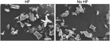 | ||
| Fig. 1 SEM images of MIL-53(Fe)[H2O] synthesized with (left) and without HF (right). The scale bar at the bottom right indicates a length of 20 μm. | ||
Fig. 2 shows the SHG images of the hydrated forms of the fluoride doped Fe(OH/F)(BDC)·[H2O] and non-doped Fe(OH)(BDC)·[H2O] crystals alongside their optical images. It is clear that crystals containing fluoride anions, significantly generate SHG. In contrast, the non-doped Fe(OH)(BDC)·[H2O] does not generate SHG, which is in agreement with the structural model determined from X-ray powder diffraction (XRPD) data in the centrosymmetric P21/c space group, belonging to the C2h point group.11 The SHG signal of the fluorinated MOF Fe(OH/F)(BDC)·[H2O] indicates the occurrence of an acentric organization, which is not in agreement with the previously reported structural model proposed in the centric C2/c space. However, centric C2/c and acentric Cc space groups cannot be distinguished from diffraction in terms of systematic extinctions. Moreover, powder diffraction analysis relies on a large assembly of crystallites: even if each crystal could be polar, if there is an equal probability to get a polar arrangement in one direction or the opposite (likely in the case of an ordering of the guest molecules), the absolute structure cannot be determined by PXRD, and only the averaged centrosymmetric structure can be obtained. Indeed, the disordered water molecules found in the centrosymmetric structure of Fe(OH/F)(BDC)·[H2O] could either correspond to a ‘true’ disorder or result from such mixing of polar crystals. Moreover, a non-centrosymmetric ordering that is only due to the ordering of OH and F anions, would very likely not be detected even from single crystal data, due to the too low electronic density difference between the two anions which does not allow to distinguish them.
To quantify how SHG active the fluoride containing crystals are, the effective second order nonlinear optical (NLO) coefficient <deff> was determined. Rather than simply comparing the SHG-intensity with the SHG-intensity of a reference material, the coefficient <deff> allows a comparison of different NLO-active materials, as it is independent of the crystallite size and refractive index of the materials.24 Considering the <deff> value, the activity of the fluorinated MIL-53(Fe) can be put into perspective. A detailed description of the calculation is given in the ESI.† The <deff> value obtained for Fe(OH/F)(BDC)·[H2O] is 0.006 pm V−1. For comparison, amino functionalized MIL-53(Al)-NH2 exhibits a <deff> value of 0.05 pm V−1 and commercial inorganic NLO materials (e.g. KDP, BBO, KTP and LiIO3) have values ranging from 0.4 to 15 pm V−1.4
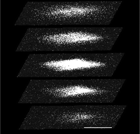
To exclude the possibility of the SHG signal solely being a surface effect, we recorded 3D images of single crystals. Fig. 3 presents a z-sliced 3D image of a crystal. The sections in the middle of the crystal are highly SHG active, confirming that the non-centrosymmetric organization is originating from the bulk of the crystal.
It is clear that the fluorine atoms incorporated in the structure play a crucial role in the non-centrosymmetric ordering. Also a chlorinated sample was prepared by adding HCl as a modulator to the synthesis mixture, but this sample lost its SHG activity after a few weeks and was therefore not studied further. Since the inorganic anions F− and OH− affect the ordering of the guest molecules inside the pores, it is reasonable to assume that also the guest molecules contribute to the non-centrosymmetric ordering.11 In addition, the presence of adsorbates in the pores can further modify the highly flexible crystalline structure of MIL-53, which is associated with important structural changes and, by consequence, can potentially affect the SHG signal.18
The importance of the nature of the guest molecules for the SHG signal was verified by exchanging water molecules with different solvents, using the procedure previously described by Millange et al.19 Both the fluorinated and non-fluorinated crystals were measured with water, pyridine, DMF, chloroform, ethanol, methanol, butanol, p-xylene and toluene in the pores. As can be seen in the ESI,† none of the non-fluorinated crystals generate SHG, whereas all fluorinated samples generate SHG, regardless the solvent's nature. The SHG signal is equally strongly observed when using para-xylene as the adsorbate. This is a centrosymmetric molecule, implying that it cannot be ordered by itself in a non-centrosymmetric way in the pores. Thus, the non-centrosymmetry must find its origin not solely in an ordering of the guest molecules, but also in the framework itself, likely through the arrangement of the fluoride ions in the inorganic chain. The series of guest molecules that induce the observed SHG-response is so diverse, that the degree of polarity and the potential for hydrogen bond formation do not seem to be vital in inducing the polar structure. The MIL-53 structure is a flexible, “breathing” structure which adapts upon adsorption of guest molecules to optimize dispersive forces between host and guest. Apparently, for fluorinated MIL-53(Fe), the phase transition that occurs upon guest adsorption, invariably leads to a polar structure of the framework itself.
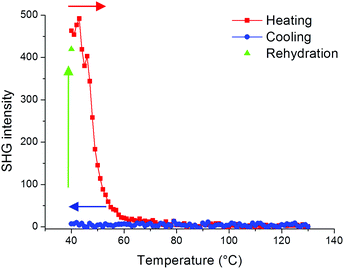
In order to further evaluate the role of guest molecules, the SHG intensity of Fe(OH/F)(BDC)·[butanol] was recorded during in situ heating to 130 °C and subsequent cooling under nitrogen flow to obtain Fe(OH/F)(BDC) crystals with empty pores. Water was not suitable as a guest molecule to obtain the empty crystals, as water molecules tend to adsorb strongly in the MIL-53(Fe) network and are thus extremely difficult to fully remove from the pores (see also ESI†).20Fig. 4 shows that the SHG signal completely vanishes upon removal of butanol guest molecules from the pores, indicating that the non-centrosymmetric organization has disappeared and only centrosymmetric crystals are left. During cooling under nitrogen the signal remains zero. To further test the hypothesis that guest molecules contribute to the non-centrosymmetric organization, the SHG signal of the empty pore Fe(OH/F)(BDC) crystals was regenerated by allowing water molecules to enter the empty pores by bringing the crystals under ambient conditions overnight. Indeed, as can be seen in Fig. 4 a strong SHG-signal was recovered, indicative of a reversal to a non-centrosymmetric organization.
To probe the symmetry of the non-centrosymmetric organization, larger MIL-53(Fe) crystals doped with fluoride were grown to easily distinguish single crystals in microscopy images. The point group symmetry was determined via polarized nonlinear optical microscopy, using the testing procedure as developed by van der Veen et al.22,23 The full measurement procedure is described in the ESI.† Essentially, the magnitude of the SHG response is followed while varying the plane of polarization of either the incident or detected light; or the sample is rotated while keeping the planes of incident and detected light either parallel or perpendicular to each other. With the polarized nonlinear optical microscopy procedure the organization of Fe(OH/F)(BDC)·[H2O] was determined to belong to the acentric and polar space group Cc, which falls under the monoclinic Cs point group.
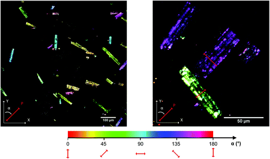
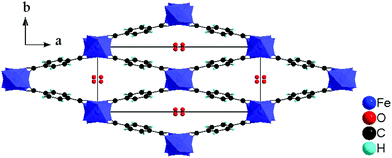
The imaging mode of the nonlinear optical microscope allows to locally probe the structural properties down to the diffraction limit. This allows to evaluate whether the polarization direction is parallel over the entire crystal, or whether crystals are divided in polar domains. To determine the polar distribution, a map was created revealing the direction of the local polarization. For this map the polarization direction per pixel was measured and given a color code, representing the angle α between the polarization direction of the crystal area and the Y-axis of the image plane. The measurement procedure was previously described by Van Cleuvenbergen et al. and is detailed in the ESI.†![[thin space (1/6-em)]](https://www.rsc.org/images/entities/char_2009.gif) 28 The result is displayed in Fig. 5. A highly homogeneous distribution of the polarization direction is evidenced since all the crystals appear uniformly colored. The darker and lighter lines along the larger axis are due to the cracks present along the crystals, as can be distinguished on the SEM image (see ESI†). It is clear that the polar axis runs along the short dimension of the crystals, as indicated by the red arrows in Fig. 5. By evaluation of the peak width on the X-ray diffraction patterns, one can assign the long dimension of crystals to the a axis. The polar axis thus lies in the b,c plane, possibly along the pore axis (c axis, see also Fig. 6).
28 The result is displayed in Fig. 5. A highly homogeneous distribution of the polarization direction is evidenced since all the crystals appear uniformly colored. The darker and lighter lines along the larger axis are due to the cracks present along the crystals, as can be distinguished on the SEM image (see ESI†). It is clear that the polar axis runs along the short dimension of the crystals, as indicated by the red arrows in Fig. 5. By evaluation of the peak width on the X-ray diffraction patterns, one can assign the long dimension of crystals to the a axis. The polar axis thus lies in the b,c plane, possibly along the pore axis (c axis, see also Fig. 6).
With the SHG polarization map, a clear image of the polarization distribution is obtained. However this method only provides information on the direction of the polarization but not on the sense. It is possible that there coexist domains with the same direction, but of opposite sense. To determine whether the crystals are unipolar or multipolar, the Fe(OH/F)(BDC)·[H2O] crystals were measured with scanning pyroelectric microscopy (SPEM), as this technique provides information about the absolute orientation (the phase) of the polarization. The technique is based on the ability of polar materials to temporarily generate an electric current upon a temperature change. Pyroelectric microscopy is a proven technique to detect polar symmetry on the micrometer scale, using localized photothermal modulation to obtain a pyroelectric response. This local response is proportional to the polarization in both amplitude and orientation. The technique is sensitive to polar symmetry and it visualizes differences in polar orientation, meaning it can identify uni-, bi- or multipolarity along the different crystal axes. From the image in Fig. 7, it is clear that the crystal is unipolar as all the arrows have the same direction and sense.
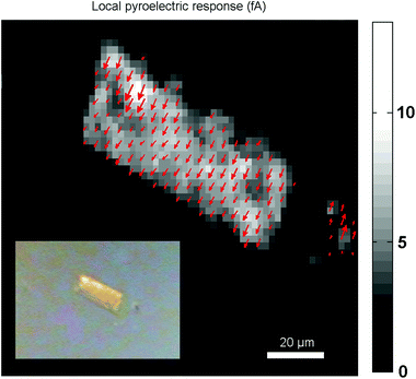 | ||
| Fig. 7 The local pyroelectric response map reveals a unipolar response from the Fe(OH/F)(BDC)·[H2O] crystal. Modulation frequency is 2025 Hz, laser power is 100 mW. Inset: optical image. | ||
Summarizing, while the X-ray diffraction method normally used for the structure determination of MOF crystals cannot always distinguish whether Fe(OH/F)(BDC) or its guests are organized in an acentric or centric fashion, the combined evidences from SHG and pyroelectric microscopy reveal that in the structure filled with guest molecules, a polar organization is present. Based on the control experiments on hydrated, dehydrated and solvent exchanged Fe(OH/F)(BDC), it seems most likely that the partial substitution of hydroxyl groups by fluoride anions leads to the creation of a polar arrangement when guest molecules are present. Such arrangement is not detected by XRPD analysis, which relies on a large assembly of crystals which can have polar axes of opposite directions.
Conclusions
In conclusion, MIL-53(Fe) synthesized with HF displays a polar organization due to an interplay between the fluorine atoms incorporated in the structure and the guest molecules occluded in the pores. This is not observed in non-fluorinated MIL-53(Fe). This polar organization even occurs when centrosymmetric guest molecules are included, hence the fluorinated MIL-53(Fe) structure itself is polar upon guest inclusion. Upon filling the pores with adsorbate, the framework adapts its structure to optimize host–guest dispersion forces. Due to the occurrence of polarity only for the fluorinated framework, this phase transition likely causes a reorganisation of the fluorine atoms in the inorganic chains with an overall polarity.The polar organisation was not previously detected with XRPD, since this gives an averaged structure for an assembly of crystals. In addition, with SHG scanning microscopy we were able to probe the organization locally and reveal that the polarity arises from a uniform unidirectional organization in the crystals, with the polar axis perpendicular to the larger axis of the crystal. Polar metal–organic frameworks have potential applications as non-linear optical, piezoelectric, pyroelectric and ferroelectric materials. The discovery of this non-centrosymmetric organization opens up perspectives on how doping MOFs with fluoride can induce useful properties.
Experimental
Synthesis
MIL-53(Fe) with and without HF was synthesized by the procedure as described by Guillou et al.11 In a Teflon-lined steel autoclave FeCl3·6H2O (1 mmol), 1,4-benzenedicarboxylic acid (BDC) (1 mmol) and N,N-dimethylformamide (DMF) (5 mL) were added. The MIL-53(Fe) MOF was crystallized at 150 °C for 3 days. For the doped MIL-53(Fe), the same quantities were used and in addition HF (Aldrich, 40%, 1 mmol, 0.044 mL) was added to the reaction mixture. After synthesis, the solid was washed two times with DMF to remove BDC from the pores, two times with MeOH to remove the DMF and dried for several days at 60 °C. MIL-53(Fe) larger crystals were solvothermally synthesized from FeCl3·6H2O (1 mmol) and 1,4-benzenedicarboxylic acid (BDC) (1.5 mmol) in N,N-dimethylformamide (DMF) (10 mL) with HF (Prolabo, 5 M, 0.025 mL) at 150 °C for 3 days. The solid was washed once in DMF and two times in H2O and dried for several days at 60 °C.For all Second Harmonic Generation Microscopy experiments a femtosecond pulsed InSight DeepSee laser from Spectra-Physics was used, operating at a wavelength of 800 nm. For the quantitative SHG intensity calculation, the SHG heating experiments and the point group symmetry determinations a customized inverted wide-field Olympus microscope was used with a Thorlabs long working distance 15× objective. Images were recorded in transmission mode with an EM-CCD camera from Hamamatsu. In this set-up a rotating sheet analyzer is easily integrated and, in combination with a rotating halfwave plate, polarization patterns for the SHG point group determination are recorded. For heating experiments crystals were placed in a Linkam stage, which was mounted on the microscope. The Linkam stage was flushed with a constant N2 flow of 1.2 bar. The SHG signal was followed in time during the heating of the sample. The mapping of the polarization within the crystals occurred on an Olympus FLUOVIEW Laser Scanning Multiphoton Microscope (FV1200MPE) with a Thorlabs 15× long working distance objective. For the z-sliced 3D image an Olympus 60× water immersion objective was used. For image processing ImageJ and Fiji were used with the VisBio plugin and the Temporal-Color Code macro.
XRPD reflection patterns were recorded on a STOE STADI MP in Bragg-Brentano mode (2θ–θ geometry; Cu Kα1 source) using a linear position sensitive detector. SEM micrographs were recorded on a JEOL SEM after coating with Au.
Acknowledgements
The authors would like to acknowledge K. Miura for the Temporal-Code macro and C. Rueden and A. Sorber for the VisBio plugin. KM and DDV are grateful to Belspo for funding in the IAP project Functional Supramolecular Systems. DDV, TV and MvdV are grateful for the financial support from the Hercules Foundation and to FWO.Notes and references
- P. Falcaro, R. Ricco, C. M. Doherty, K. Liang, A. J. Hill and M. J. Styles, Chem. Soc. Rev., 2014, 43, 5513–5560 RSC.
- M. Guo, H.-L. Cai and R.-G. Xiong, Inorg. Chem. Commun., 2010, 13, 1590–1598 CrossRef CAS.
- C. Wang, T. Zhang and W. Lin, Chem. Rev., 2012, 112, 1084–1104 CrossRef CAS PubMed.
- P. Serra-Crespo, M. A. van der Veen, E. Gobechiya, K. Houthoofd, Y. Filinchuk, C. E. A. Kirschhock, J. A. Martens, B. F. Sels, D. E. De Vos, F. Kapteijn and J. Gascon, J. Am. Chem. Soc., 2012, 134, 8314–8317 CrossRef CAS PubMed.
- G. P. Nagabhushana, R. Shivaramaiah and A. Navrotsky, J. Am. Chem. Soc., 2015, 137, 10351–10356 CrossRef CAS PubMed.
- H. Cui, B. Zhou, L.-S. Long, Y. Okano, H. Kobayashi and A. Kobayashi, Angew. Chem., Int. Ed., 2008, 47, 3376–3380 CrossRef CAS PubMed.
- X.-Y. Dong, B. Li, B.-B. Ma, S.-J. Li, M.-M. Dong, Y.-Y. Zhu, S.-Q. Zang, Y. Song, H.-W. Hou and T. C. W. Mak, J. Am. Chem. Soc., 2013, 135, 10214–10217 CrossRef CAS PubMed.
- G. Zahn, P. Zerner, J. Lippke, F. L. Kempf, S. Lilienthal, C. A. Schröder, A. M. Schneider and P. Behrens, CrystEngComm, 2014, 16, 9198–9207 RSC.
- G. Férey, F. Millange, M. Morcrette, C. Serre, M.-L. Doublet, J.-M. Grenèche and J.-M. Tarascon, Angew. Chem., Int. Ed., 2007, 46, 3259–3263 CrossRef PubMed.
- C. Combelles, M. Ben Yahia, L. Pedesseau and M.-L. Doublet, J. Phys. Chem. C, 2010, 114, 9518–9527 CAS.
- N. Guillou, R. I. Walton and F. Millange, Z. Kristallogr., 2010, 225, 552–556 CrossRef CAS.
- R. I. Walton, A. S. Munn, N. Guillou and F. Millange, Chem. – Eur. J., 2011, 17, 7069–7079 CrossRef CAS PubMed.
- F. Vermoortele, B. Bueken, G. Le Bars, B. Van de Voorde, M. Vandichel, K. Houthoofd, A. Vimont, M. Daturi, M. Waroquier, V. Van Speybroeck, C. Kirschhock and D. E. De Vos, J. Am. Chem. Soc., 2013, 135, 11465–11468 CrossRef CAS PubMed.
- H. Wu, Y. S. Chua, V. Krungleviciute, M. Tyagi, P. Chen, T. Yildirim and W. Zhou, J. Am. Chem. Soc., 2013, 135, 10525–10532 CrossRef CAS PubMed.
- B. Bueken, H. Reinsch, N. Reimer, I. Stassen, F. Vermoortele, R. Ameloot, N. Stock, C. E. A. Kirschhock and D. De Vos, Chem. Commun., 2014, 50, 10055–10058 RSC.
- M. Vandichel, J. Hajek, F. Vermoortele, M. Waroquier, D. E. De Vos and V. Van Speybroeck, CrystEngComm, 2015, 17, 395–406 RSC.
- F. Millange, N. Guillou, R. I. Walton, J.-M. Grenèche, I. Margiolaki and G. Férey, Chem. Commun., 2008, 4732–4734 RSC.
- G. Férey and C. Serre, Chem. Soc. Rev., 2009, 38, 1380–1399 RSC.
- F. Millange, C. Serre, N. Guillou, G. Férey and R. I. Walton, Angew. Chem., Int. Ed., 2008, 47, 4100–4105 CrossRef CAS PubMed.
- F. Millange, N. Guillou, R. I. Walton, J.-M. Grenèche, I. Margiolaki and G. Férey, Chem. Commun., 2008, 4732–4734 RSC.
- G. de Combarieu, M. Morcrette, F. Millange, N. Guillou, J. Cabana, C. P. Grey, I. Margiolaki, G. Férey and J.-M. Tarascon, Chem. Mater., 2009, 21, 1602–1611 CrossRef CAS.
- M. A. van der Veen, F. Vermoortele, D. E. De Vos and T. Verbiest, Anal. Chem., 2012, 84, 6386–6390 CrossRef CAS PubMed.
- M. A. van der Veen, F. Vermoortele, D. E. De Vos and T. Verbiest, Anal. Chem., 2012, 84, 6378–6385 CrossRef CAS PubMed.
- M. A. Van Der Veen, T. Verbiest and D. E. De Vos, Microporous Mesoporous Mater., 2013, 166, 102–108 CrossRef CAS.
- Handbook of Biomedical Nonlinear Optical Microscopy, ed. B. R. Masters and P. T. C. So, Oxford University Press, USA, New York, 1st edn, 2008 Search PubMed.
- R. W. Boyd, Nonlinear Optics, Elsevier, 2008 Search PubMed.
- H. Reinsch, M. A. van der Veen, B. Gil, B. Marszalek, T. Verbiest, D. E. De Vos and N. Stock, Chem. Mater., 2013, 25, 17–26 CrossRef CAS.
- S. Van Cleuvenbergen, G. Hennrich, P. Willot, G. Koeckelberghs, K. Clays, T. Verbiest and M. A. van der Veen, J. Phys. Chem. C, 2012, 116, 12219–12225 CAS.
Footnote |
| † Electronic supplementary information (ESI) available. See DOI: 10.1039/c5dt04632g |
| This journal is © The Royal Society of Chemistry 2016 |


