
 Open Access Article
 This Open Access Article is licensed under a
 Creative Commons Attribution 3.0 Unported Licence
Effects of calcination and activation conditions on ordered mesoporous carbon supported iron catalysts for production of lower olefins from synthesis gas†
M.
Oschatz
*a,
T. W.
van Deelen
a,
J. L.
Weber
a,
W. S.
Lamme
 a,
G.
Wang
a,
B.
Goderis
b,
O.
Verkinderen
b,
A. I.
Dugulan
c and
K. P.
de Jong
*a
a,
G.
Wang
a,
B.
Goderis
b,
O.
Verkinderen
b,
A. I.
Dugulan
c and
K. P.
de Jong
*a
aInorganic Chemistry and Catalysis, Debye Institute for Nanomaterials Science, Utrecht University, Universiteitsweg 99, 3584 CG Utrecht, The Netherlands. E-mail: M.Oschatz@uu.nl; K.P.deJong@uu.nl
bPolymer Chemistry and Materials, Catholic University of Leuven, Celestijnenlaan 200F, 3001 Heverlee, Belgium
cFundamental Aspects of Materials and Energy Group, Delft University of Technology, Mekelweg 15, 2629 JB Delft, The Netherlands
First published on 14th November 2016
Abstract
Lower C2–C4 olefins are important commodity chemicals usually produced by steam cracking of naphtha or fluid catalytic cracking of vacuum gas oil. The Fischer–Tropsch synthesis of lower olefins (FTO) with iron-based catalysts uses synthesis gas as an alternative feedstock. Nanostructured carbon materials are widely applied as supports for the iron nanoparticles due to their weak interaction with the metal species, facilitating the formation of catalytically active iron carbide. Numerous synthetic approaches towards carbon-supported FTO catalysts with various structures and properties have been published in recent years but structure-performance relationships remain poorly understood. We apply ordered mesoporous carbon (CMK-3) as a support material with well-defined pore structure to investigate the relationships between calcination/activation conditions and catalytic properties. After loading of iron and sodium/sulfur as the promoters, the structures and properties of the FTO catalysts are varied by using different calcination (300–1000 °C) and activation (350 or 450 °C) temperatures followed by FTO testing at 1 bar, 350 °C, H2/CO = 1. Carbothermal reduction of iron oxides by the support material occurs at calcination temperatures of 800 or 1000 °C, leading to a higher ratio of catalytically active iron(carbide) species but the catalytic activity remains low due to particle growth and blocking of the catalytically active sites with dense graphite layers. For the samples calcined at 300 and 500 °C, the formation of non-blocked iron carbide can be enhanced by activation at higher temperatures, leading to higher catalytic activity. Olefin selectivities of ∼60%C in the formed hydrocarbons with methane of ∼10%C are achieved for all catalysts under FTO conditions at low CO conversion. The influence of the calcination temperature is further investigated under industrially relevant FTO conditions. Promoted CMK-3-supported catalysts obtained at low calcination temperatures of 300–500 °C show stable operation for 140 h of time on stream at 10 bar, 340 °C, H2/CO = 2.
Introduction
Lower olefins (C2–C4) are important commodity chemicals which are conventionally produced from naphtha or vacuum gas oil. In the last years, non-oil based routes are more and more in focus for the production of C2–C4 olefins from synthesis gas (a mixture of CO and H2). These compounds can be produced either via indirect routes,1 bifunctional catalysts,2,3 or by the Fischer–Tropsch to olefins (FTO) process.4,5 FTO synthesis is a method for the direct production of lower olefins from synthesis gas. Since syngas can be obtained from biomass, coal, or natural gas,6 FTO provides a non-oil-based route towards these chemicals. Iron-based catalysts are widely studied for FTO which is commonly performed at high temperatures (300–350 °C) to achieve a large fraction of short-chain molecules.7,8 Iron has a lower methanation activity, high olefin/paraffin selectivity, high resistance to contaminants, high water-gas-shift activity, and low costs in comparison to cobalt-based catalysts.9,10 The FTO reaction proceeds through a surface carbide mechanism and can be considered as polymerization process. Hence, in terms of chain length, the product distribution can be described by the Anderson–Schulz–Flory model.5,11 Iron carbide species are the catalytically active phase although other compounds such as iron oxides and metallic iron might also be present under FTO conditions. The selectivity towards C2–C4 olefins, activity, and stability of iron-based FTO catalysts can be further increased by the use of promoters.12–14 Especially a combination of sodium and sulfur reduces the selectivity towards the low-value product methane and increases the olefin/paraffin ratio as well as the catalytic activity.15–17Bulk iron catalysts suffer from distinct particle agglomeration and particle growth, leading to mechanical breakdown and short lifetimes.5 Hence, the metal is often immobilized on porous support materials to achieve sufficient stability. Nanostructured carbon materials are particularly attractive candidates for the dispersion of iron nanoparticles due to their high surface area, adjustable textural properties, and controllable surface chemistry.18–23 The irreversible formation of non-reducible and hence non-active iron species as it can occur for silica and high surface area alumina supports is prevented due to the weak interaction between carbon materials and the iron nanoparticles.16 However, sufficient knowledge about the interplay between promoters, catalytically active iron species, and support materials during catalyst preparation, activation, and catalytic reaction is still not available. Research about iron nanoparticles directly encapsulated within carbon shells also accelerated in the last years.8,24–26 Although graphite covering of metal nanoparticles will surely result in more stable catalysts by preventing agglomeration, the effect of such a shielding layer on catalytic activity and selectivity is not yet sufficiently illuminated. Carbon nanotubes, carbon nanofibers and graphene are widely applied as model supports for FTO catalysts.27–29 In contrast to such substances with high external surface area, nanoporous carbon materials are less investigated. However, especially ordered mesoporous carbon materials are useful model catalyst supports due to their long-range ordered pore system and the narrow pore size distribution.30–33
Significant efforts have been made to get better understanding of the reaction/deactivation mechanisms,34–36 promoter effects,17 particle size influence,37 and support properties12,16,38 for supported FTO catalysts but the interplay between the inorganic nanomaterials and the active species is still barely understood. Especially the influence of the synthesis and pre-treatment conditions (e.g., during calcination and activation) on the catalysts structures and catalytic properties need to be investigated in more detail. We utilize ordered mesoporous carbon materials (denoted as CMK-3; CMK: carbon mesostructured by KAIST)39 as supports with well-defined and long-range ordered pore structure for iron-based FTO catalysts, containing sodium and sulfur as promoters. Due to the unique structure of CMK-3, effects of different conditions during catalyst synthesis or catalyst reduction can be investigated and interpreted in a straightforward way and transferred to rather commercially relevant support materials.
Incipient wetness impregnation (IWI) was chosen for loading of iron as one of the most scalable methods for industrial synthesis of heterogeneous catalysts.40 Sodium and sulfur were added as promoters in order to achieve high C2–C4 olefin selectivity and to suppress methane formation. The catalyst precursors were calcined at different temperatures (300–1000 °C), leading to different iron particle sizes and iron phases due to reduction of iron oxides by the carbon support at higher temperature. Catalytic testing under FTO conditions at 1 bar shows that the activity strongly depends on both the applied calcination and activation temperature. Despite the presence of more reduced iron species, blocking of the catalytically active sites with graphite layers after high-temperature calcinations decreases the catalytic activity. This observation is also confirmed under industrially relevant FTO conditions at 10 bar. These findings provide general guidelines for the design of stable promoted FTO catalysts. Research on graphite-encapsulated iron particles accelerated over the last years but encapsulation of iron particles within porous supports combined with efficient activation and promoters can be applied instead to combine high stability with high activity.
Experimental section
Materials synthesis
Structural characterization
Nitrogen physisorption isotherms were measured at −196 °C on a Micromeritics TriStar 3000 instrument. Prior to all measurements, samples were dried at 150 °C under flowing nitrogen. Specific surface areas (SSAs) were calculated using the multi-point BET method (0.05 < p/p0 < 0.25). Pore volumes (Vpore), pore size distributions (PSDs), and average pore sizes were determined by the BJH method by using the adsorption branches of the isotherms.Inductively coupled plasma-optical emission spectroscopy (ICP-OES) measurements were performed with an SPECTRO ARCOS ICP-OES instrument after aqua regia extraction of the samples.
Small-angle X-ray scattering (SAXS) curves were measured on a XEUSS SAXS/WAXS setup from Xenocs, equipped with a MoKα1-source (λ = 0.071 nm) and a 2D Mar detector. The samples were mounted in borosilicate glass capillaries (outer diameter 1 mm; wall thickness 0.01 mm), and the acquisition time for the scattered intensity was 60 min. The 2D scattering patterns were azimuthally averaged using the ConeX software41 and the correction for the scattering by the sample holder was done as described elsewhere.42 The SAXS patterns are expressed as the scattered intensity against the scattering wave vector q = 4π/λ![[thin space (1/6-em)]](https://www.rsc.org/images/entities/char_2009.gif) sin(θ), where θ is half the scattering angle. Because absolute intensities were not measured, and to make the comparison easier between the various samples, the scattering patterns were normalised to the highest intensity measured for each sample. Wide-angle X-ray diffraction measurements were carried out with a Bruker D2 PHASER operating with a CuKα1 radiation source (λ = 0.154 nm).
sin(θ), where θ is half the scattering angle. Because absolute intensities were not measured, and to make the comparison easier between the various samples, the scattering patterns were normalised to the highest intensity measured for each sample. Wide-angle X-ray diffraction measurements were carried out with a Bruker D2 PHASER operating with a CuKα1 radiation source (λ = 0.154 nm).
Transmission 57Fe Mössbauer absorption spectra were collected in situ at 27 °C with a conventional constant-acceleration spectrometer using a 57Co(Rh) source. Velocity calibration was carried out using an α-Fe foil. The Mössbauer spectra were fitted using the Mosswinn 4.0 program.
Hydrogen temperature-programmed reduction (H2-TPR) was carried out by heating 50–60 mg of the calcined catalysts up to 800 °C with a rate of 5 °C min−1 in 50 mL min−1 of a gas mixture of 5% H2 in Ar with a Micromeritics Autochem II 2920 chemisorption analyzer. Prior to heating, samples were dried at 100 °C for 1 h under flowing Ar.
Hydrogen thermogravimetric analysis (H2-TGA) of the calcined catalysts was performed with a Perkin Elmer Pyris1TGA instrument. Samples were heated from room temperature to 800 °C with a rate of 5 °C min−1 in 50 mL min−1 of a gas mixture of 20% H2 in Ar.
Transmission electron microscopy (TEM), high angle annular dark field (HAADF)-scanning transmission electron microscopy (STEM) imaging, and energy dispersive X-ray spectroscopy (EDX) analysis were performed on a FEI Talos F200X transmission electron microscope, operated at 200 kV and equipped with a high-brightness field emission gun (X-FEG) and a Super-X G2 EDX detector.
Catalytic studies
Results and discussion
Structural analysis of the FTO catalysts after calcination at different temperatures
After infiltration of the iron and promoter precursors into the pore system of the CMK-3 support with the IWI technique and subsequent drying, Fe@CMK-3 catalysts were obtained by calcination under inert atmosphere at maximum temperatures of 300, 500, 800, and 1000 °C. The filling of the pore system of CMK-3 with iron nanoparticles significantly decreases the apparent SSA and pore volume as compared to the pristine support material (Table 1 and ESI,† Fig. S1). As indicated by the narrow hysteresis loops in the nitrogen physisorption isotherms of the calcined catalysts (Fig. 1A), a well-defined mesoporosity is preserved after calcination. However, the presence of the iron species leads to a decrease of the average pore size as compared to the pristine support (Table 1). The measured SSAs, pore volumes, and average pore sizes of the catalysts steadily increase with increasing calcination temperature. This indicates that a larger fraction of iron particles is encapsulated inside the CMK-3 pore system at lower calcination temperature. This confinement apparently leads to the blocking of pores which are not available for the probe molecules. As already indicated by the broadening of the hysteresis loops in the nitrogen physisorption isotherms of the catalysts, the BJH pore size analyses (Fig. 1B) further show a slight broadening of the PSD with increasing calcination temperature. The change of the support pore structure during calcination is related to the increasing reactivity between CMK-3 and the iron species at higher temperatures. The reductive properties of carbon supports have already been reported for iron- and cobalt-based catalysts.24,31 At higher calcination temperatures, CMK-3 is partially consumed because it acts as an oxygen acceptor leading to the carbothermal reduction of the iron oxide species. This reductive effect of the support is more pronounced at higher temperatures as indicated by the increased mass loss at higher calcination temperatures (Table 1).| Catalyst | SSA (m2 g−1) | V Pore (cm3 g−1) | d Pore,Aver. (nm) | Fe/Na/S (wt%) | Δm calc. (%) | FeSize after calc. (nm) |
|---|---|---|---|---|---|---|
| Fe@CMK-3-300 | 439 | 0.35 | 2.5 | 9.2/2.7/0.21 | −36 | 2.5 ± 0.6 |
| Fe@CMK-3-500 | 527 | 0.45 | 2.7 | 13.7/3.9/0.27 | −39 | 5.3 ± 2.9 |
| Fe@CMK-3-800 | 629 | 0.52 | 3.2 | 16.5/2.1/0.33 | −47 | 6.8 ± 3.2 |
| Fe@CMK-3-1000 | 718 | 0.6 | 3.4 | 18.8/0.2/0.35 | −53 | 7.4 ± 2.4 |
| Parent CMK-3 | 1590 | 1.58 | 4.1 | Not measured | — | — |
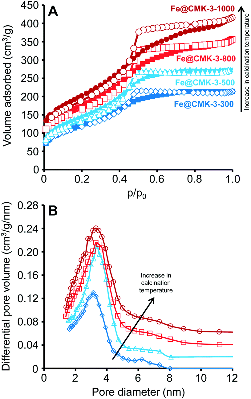 | ||
| Fig. 1 (A) Nitrogen adsorption/desorption (filled symbols/empty symbols) isotherms (−196 °C) as well as (B) BJH pore size distributions calculated from the adsorption branch of Fe@CMK-3-300 (dark blue diamonds), Fe@CMK-3-500 (light blue triangles), Fe@CMK-3-800 (light red squares), and Fe@CMK-3-1000 (dark red circles). The differential pore volumes of Fe@CMK-3-500, Fe@CMK-3-800, and Fe@CMK-3-1000 are vertically offset by 0.02, 0.04, and 0.06 cm3 g−1 nm, respectively. | ||
ICP-OES analyses show a significantly higher iron content of 18.8 wt% in the Fe@CMK-3-1000 catalyst as compared to the Fe@CMK-3-300 catalyst, containing only 9.2 wt% of iron (Table 1). It should be noticed that the increase in iron content at higher calcination temperature is more distinct as expected from carbothermal reduction only. The increasing weight loss at higher temperatures indicates significant gasification of carbon and/or removal of heteroatoms present on the support surface at higher temperature. Despite the higher iron content of the catalysts calcined at higher temperatures, they show a larger SSA and pore volume. This indicates a less strong confinement of the iron particles inside their pores and hence a lower volume of blocked pores. Furthermore, carbon gasification due to the carbothermal reduction of the support leads to the formation of additional holes and the widening of existing pores. While the ratio of sulfur promoter also slightly increases with calcination temperature, sodium leaching occurs at the highest calcination temperature. Although the alkali might be present in ionic form, apparently sublimation of sodium compounds takes place.
SAXS measurements (Fig. 2A) of the pristine CMK-3 and the FTO catalysts after calcination show the typical pattern of ordered mesoporous materials with hexagonal mesopore structure for the carbon support (space group p6mm). The SAXS curves of the calcined catalysts show the peaks related to the ordered mesopore system at lower intensity. To understand this, one has to consider that the addition of a loading material to the carbon support has two main effects on the SAXS intensity.43 On one hand, the signal of the support is decreased further, because the presence of iron particles reduces the average electron-density difference between the carbonaceous pore walls and the space in between. On the second hand, there is an additional contribution to the scattering resulting from the nanostructure of the iron particles themselves. Both effects contribute to decreasing the relative intensity of the scattering peaks. For the catalysts calcined at lower temperatures, the main peak of the pristine CMK-3 is present only as shoulder whereas its intensity is more pronounced in case of the Fe@CMK-3-800 and Fe@CMK-3-1000 catalysts. This indicates a rather homogeneous dispersion of the metal particles into the pores of Fe@CMK-3-300 and Fe@CMK-3-500 in accordance to nitrogen physisorption. Their lower background at scattering vectors below q ∼ 0.05 A−1 indicates a higher uniformity of the metal loading in the Fe@CMK-3-300 and Fe@CMK-3-500 catalysts as it was previously shown for silica-supported copper catalysts.42
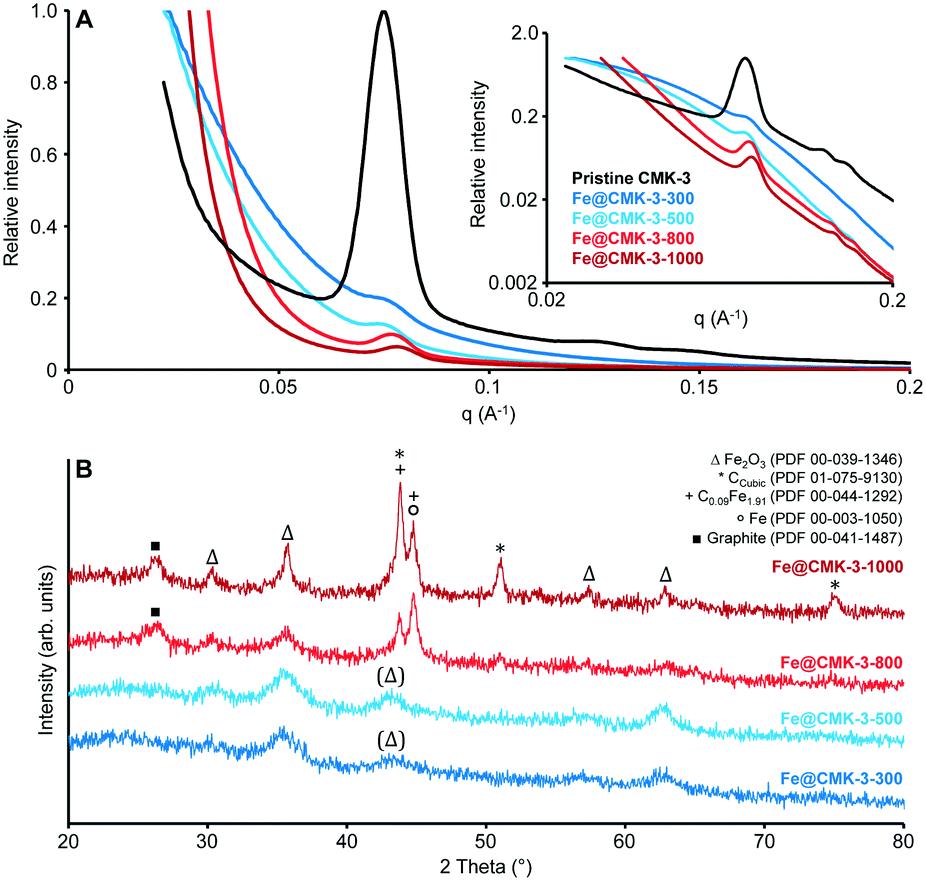 | ||
| Fig. 2 (A) Linear and logarithmic (inset) plots of the small-angle X-ray scattering curves and (B) wide angle X-ray diffraction patterns of the pristine CMK-3 (black-only shown in A), Fe@CMK-3-300 (dark blue), Fe@CMK-3-500 (light blue), Fe@CMK-3-800 (light red), and Fe@CMK-3-1000 (dark red). | ||
The proceeding reduction of iron oxide by the CMK-3 support is qualitatively proved by wide-angle XRD analysis (Fig. 2B). Calcined catalysts Fe@CMK-3-300 and Fe@CMK-3-500 show the presence of hematite nanoparticles as the only crystalline species with broad signals due to their nanoparticle dimensions and/or low crystallinity. With increasing the calcination temperature to 800 and 1000 °C, the reductive properties of the carbon support cause the formation of iron carbide species and also metallic iron. Some iron oxide species are also still present after high temperature calcination. The presence of magnetite after reduction can also not be ruled out but no Fe2+ species were detected in Mössbauer spectroscopy analyses as discussed below. The XRD signals get sharper, indicating the growth of the crystalline species. Furthermore, crystalline carbon species are detected. Graphite is formed during high-temperature calcination because iron acts as graphitization catalyst for the support.44
In accordance to XRD analysis, Mössbauer spectroscopy analyses qualitatively prove the reduction of the hematite particles occurring during calcination at 800 and 1000 °C (ESI,† Table S1, and Fig. S2). In the Fe@CMK-3-300 and Fe@CMK-3-500 catalysts, solely Fe3+ species are present after calcination. In contrast, 24% metallic iron and 14% iron carbides are detected within the calcined Fe@CMK-3-800. After calcination at 1000 °C, even 50% and 12% of the iron are present as metallic and carbidic species, respectively.
H2-TPR profiles of the calcined catalysts (Fig. 3A) show the typical multi-step reduction process of the hematite.27 The first peaks between 350 and 400 °C are related to the formation of Fe3O4 from Fe2O3 species present after calcination. The subsequent hydrogen consumption at ∼500 °C is related to the reduction to FeO followed by the formation of metallic iron at 600–700 °C. However, the shape of the reduction profile changes significantly with calcination temperature. Total hydrogen consumption normalized to the mass of catalyst gradually increases with increasing the calcination temperature from 300 to 1000 °C, respectively. This result is not in line with the presence of a higher ratio of reduced iron species after calcination at higher temperatures. H2-TGA under reducing atmosphere (Fig. 3B) show a step mass loss of the Fe@CMK-3-1000 in the range from 250–450 °C due to the reduction of the remaining iron oxide species. No further mass loss occurs at higher temperatures. The catalysts prepared at lower temperatures also show a mass loss in this temperature range but at the same time, their mass keeps decreasing, especially at temperatures above 500 °C. This effect is more pronounced for the catalysts calcined at lower temperatures. The high weight loss of the low-temperature catalysts of more than 40% is likely caused by methanation of the carbon support, occurring at high temperatures under hydrogen atmosphere in presence of iron nanoparticles.
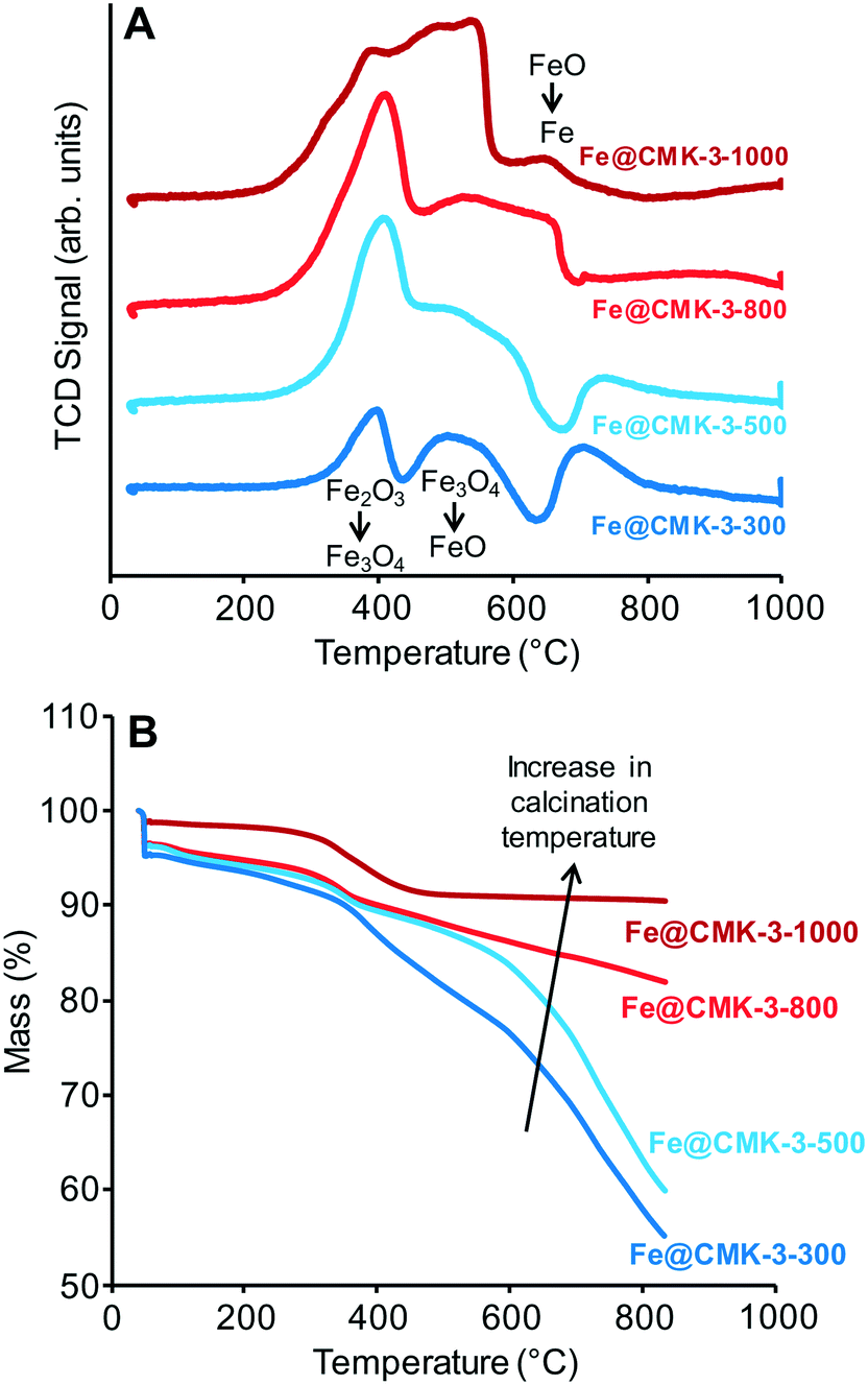 | ||
| Fig. 3 (A) H2-TPR and (B) H2-TGA curves of the calcined Fe@CMK-3-300 (dark blue), Fe@CMK-3-500 (light blue), Fe@CMK-3-800 (light red), and Fe@CMK-3-1000 (dark red) catalysts. | ||
Although a comparably high iron loading was applied, TEM investigations (Fig. 4) show that the iron-nanoparticles are small and well-dispersed within the pore systems of the supports after calcination at 300 and 500 °C. Due to the high internal pore volume, the ordered mesoporous support is able to encapsulate small iron particles at high loadings. No larger iron particles are observed at the external surface of the μm-sized support particles. Because of the encapsulation into the pore system of the support, the diameters of iron-particles (numerical average) in the Fe@CMK-3-300 (2.5 ± 0.6 nm) and the Fe@CMK-3-500 (5.3 ± 2.9 nm) remain low. At higher calcination temperatures (and therefore proceeding carbothermal reduction), the iron species grow to slightly larger diameters of 6.8 ± 3.2 nm (Fe@CMK-3-800) and 7.4 ± 2.4 nm (Fe@CMK-3-1000). As already indicated by the SAXS and nitrogen physisorption analyses, the ordered mesopore system and typical particle morphology of CMK-3 is still preserved even after calcination at high temperatures.
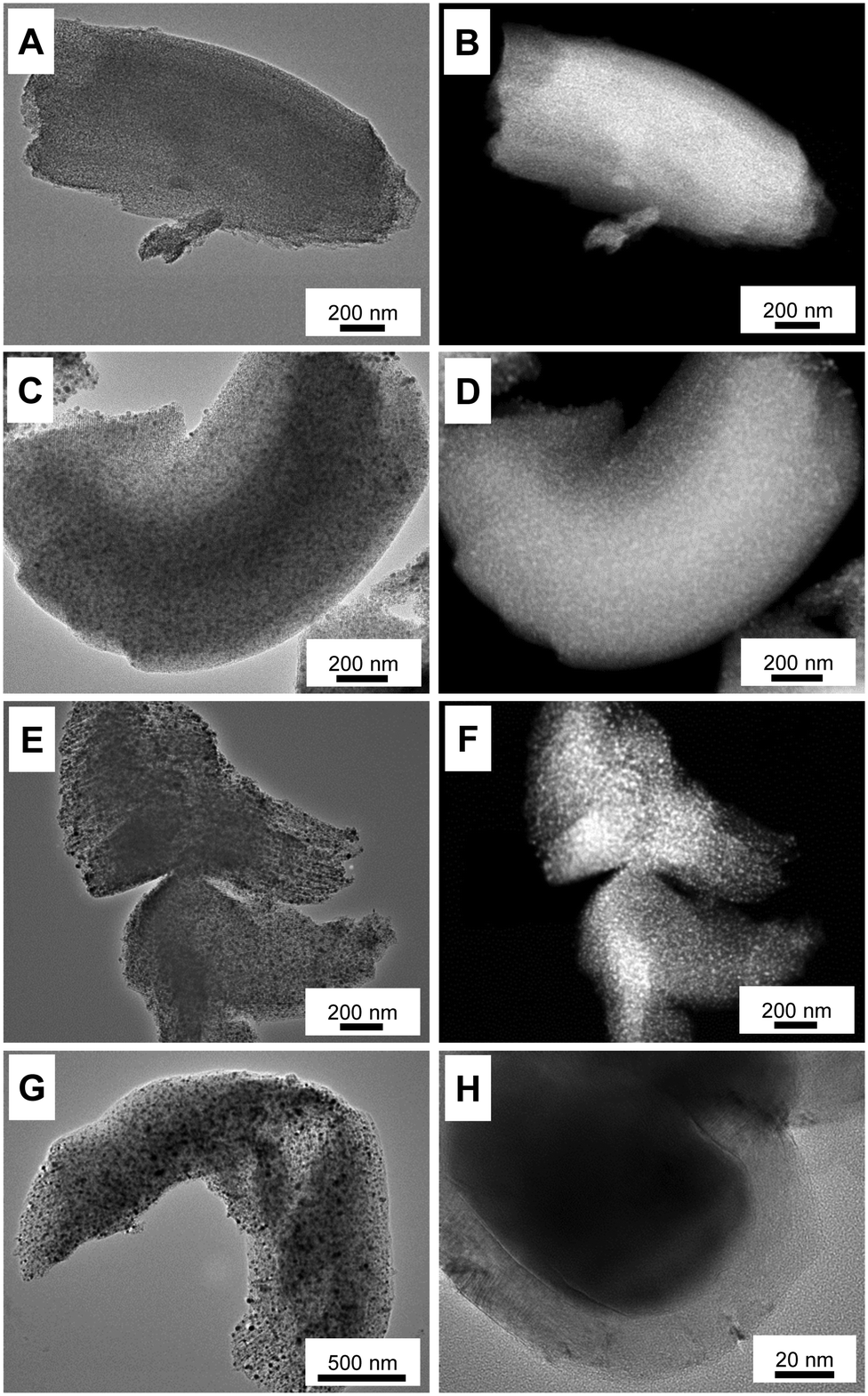 | ||
| Fig. 4 Bright-field TEM images and HAADF-STEM images of (A and B) Fe@CMK-3-300, (C and D) Fe@CMK-3-500, (E and F) Fe@CMK-3-800, and (G and H) Fe@CMK-3-1000 after calcination. | ||
EDX elemental mapping analyses of the Fe@CMK-3-500 and Fe@CMK-3-1000 after calcination show significant structural differences of the iron particles. In accordance with XRD and Mössbauer analyses, iron oxide particles are the dominant species in the catalyst calcined at low temperature (Fig. 5A). The particles are distributed over the carbon support with 1-dimensional orientation. In contrast, at higher calcination temperature, the support shows a rather folded structure more typical for graphite species than for amorphous templated porous carbons. A large part of the iron particles in this catalyst shows a core–shell structure (Fig. 4H and 5B). At higher magnification, it can be seen that the metal core is embedded into a graphite shell composed of parallel oriented graphene layers with only few defects (ESI,† Fig. S3). In agreement with Mössbauer spectroscopy analyses, the iron carbide species present in Fe@CMK-3-800 decompose to an iron–carbon core–shell structure with isolated metallic iron inside. This graphite encapsulation of the iron particles is responsible for the absence of methanation of the catalysts calcined at higher temperatures as shown in TGA under hydrogen atmosphere. In contrast to the catalyst prepared at lower temperatures, there is no clear match between the iron- and oxygen-rich areas in the EDX mapping because the Fe@CDC-1000 catalyst contains a mixture of iron species including oxides, carbides, and metallic species.
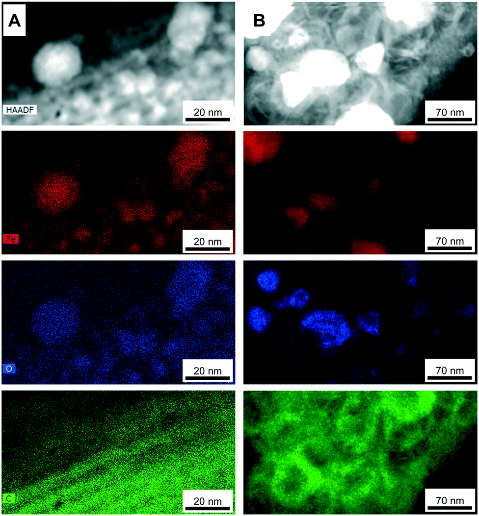 | ||
| Fig. 5 EDX elemental mapping TEM images (at the edges of CMK-3 particles with larger iron particles) of (A) Fe@CMK-3-500 and (B) Fe@CMK-3-1000 after calcination (iron-red; oxygen-blue; carbon-green). | ||
Low-pressure FTO measurements after activation at different temperatures
The influence of the calcination and activation conditions on the catalytic properties of the catalysts was studied under FTO conditions at 1 bar, 350 °C, and a H2/CO ratio of 1. Such FTO conditions lead to relatively low CO conversions, minimizing the extent of secondary reactions and heat transfer limitations (ESI,† Table S2). Although the catalytic activities determined at such low CO conversions have a relatively high experimental error, they are generally well correlated with the amount of iron carbide species determined in Mössbauer spectroscopy analyses. After activation of the Fe@CMK-3-300 catalyst under diluted hydrogen flow at 350 °C for 2 h, only 15% of the iron species are detected as FexC with Mössbauer spectroscopy (ESI,† Table S1). Their superparamagnetic state indicates very small particle sizes. After activation at 450 °C, 59% of iron species are present in metallic or carbidic state. Quantitative reduction to metallic iron is achieved at 350 °C and 450 °C for the Fe@CMK-3-1000 catalyst.Under FTO conditions at 1 bar, the catalytic activity of the Fe@CMK-3 catalysts activated at 350 °C slowly increase over the first 20 h of time on stream (TOS), likely caused by the ongoing formation of iron carbide species during exposure to syngas (Fig. 6A). Mössbauer spectroscopy analyses show that after activation at 350 °C, full carbidization did not occur even after 18 h under syngas at 1 bar (ESI,† Table S1). For the catalysts calcined at 300–800 °C, Fe2+ species are still present. Interestingly, iron partially remains metallic in the Fe@CMK-3-1000 catalyst despite the exposure to syngas at high temperature for 18 h. The initial catalytic activity of the catalysts activated at 350 °C increases at higher calcination temperature from 300 to 800 °C and then decreases again for the Fe@CMK-3-1000 catalyst (Fig. 6A). This indicates that a large part of the iron within the catalyst calcined at the highest temperature is not accessible for the syngas. Two other reasons for a drop of the activity might be the slightly larger iron particle size in this catalyst after calcination and the pronounced loss of sodium promoter during high-temperature calcination. However, a previous study on α-Al2O3-supported iron catalysts showed that the absence of sodium does not decrease the FTY at 1 bar if sulfur is present.17 In accordance to the TEM and H2-TPR/H2-TGA of the calcined catalysts, the most obvious reason for the lower activity is the shielding of the iron surface from the syngas by the graphitic carbon layers. This becomes more evident in the catalytic testing of the Fe@CMK-3 catalysts activated at 450 °C. The increase of the activation temperature increases the initial catalytic activity of the Fe@CMK-3 catalysts. While the presence of reduced iron species has the dominant influence on the catalytic activity after activation at 350 °C, the ratio of reduced iron species is higher in all catalysts after activation at 450 °C and the initial activity over the first 0–4 h of TOS increases (ESI,† Fig. S4A). The relative increase for catalysts that underwent similar calcination conditions gets more pronounced with decreasing calcination temperature. The change for the Fe@CMK-3-1000 catalyst remains low as compared to Fe@CMK-3-300. The absence of a significant response of the catalyst Fe@CMK-3-1000 to the increased activation temperature is due to the encapsulation of the active iron sites with non-porous graphitic layers, leading to blockage of large parts of the active surface. Interestingly, a large number of recent studies on carbon-supported iron or cobalt Fischer–Tropsch catalysts reports such encapsulation as attractive feature to prevent excessive growth of metal particles.8,25,26 However, according to our findings, such an encapsulation also leads to a significant decrease of the catalytic activity at otherwise comparable particle size. Because significantly higher ratios of iron carbide species are present after activation at 450 °C and 18 h of TOS (ESI,† Table S1), the iron particle size and accessibility of their surface becomes determinant for the catalytic activity and a clear increase of the FTY over the first hours of TOS can be observed with decreasing calcination temperature. After rapid initial increase of the FTY (0–4 h TOS), the CO conversion decreases due to particle growth and then increases again for some catalysts, most likely due to slight pressure increase within the fixed-bed reactors. In contrast to the catalytic activities, the selectivities are only marginally affected by the different calcination and activation conditions (Fig. 6B and ESI,† Fig. S4B). Despite the variations in promoter levels detected with ICP-OES after calcination at different temperatures, there are no drastic differences in the selectivities of the catalysts calcined and activated at different temperatures. Although the calcined Fe@CMK-3-1000 catalyst contains a lower sodium/iron ratio, its selectivity is comparable to the samples obtained at low temperature which could be due to the larger iron particles and their encapsulation into graphitic shells. Furthermore, the differences in the porosities of the supports after calcination will lead to different promoter distributions over the catalysts surfaces. At 1 bar syngas pressure, all catalysts show selectivities towards lower olefins of ∼60%C of the formed hydrocarbons. The CO2 selectivity was not measured at 1 bar. In tendency, the methane selectivity decreases with increasing calcination temperature whereas the C5+ formation increases. For similar calcination temperatures, the C5+ selectivity decreases with increasing activation temperature from 350 to 450 °C. This is also reflected by the slightly decreasing chain growth probability in the C2–C6 area (Fig. 6C and ESI,† Fig. S4C). All catalysts display deviation from the ASF distribution in terms of lower methane formation due to the presence of sulfur promoter.
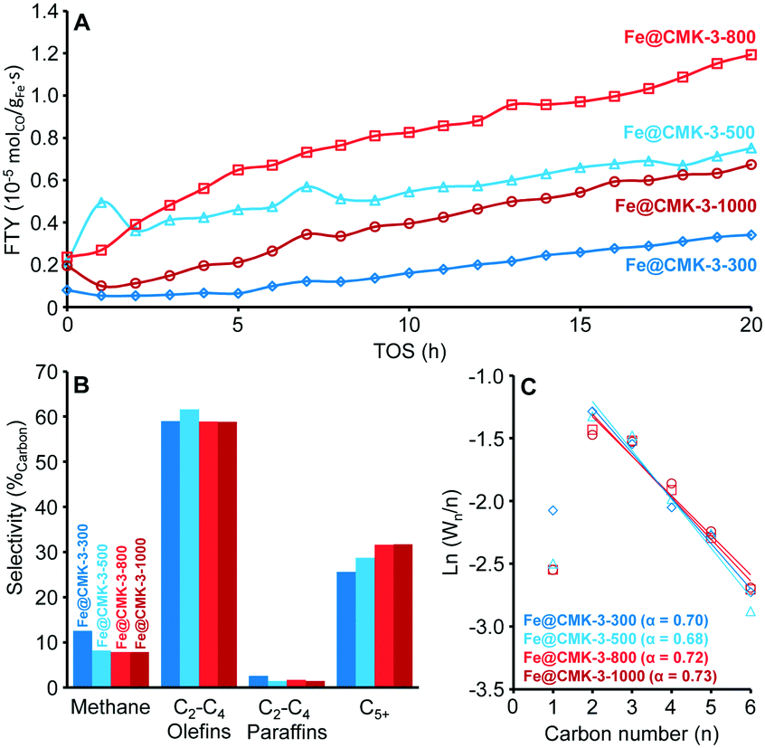 | ||
| Fig. 6 (A) Iron-weight based activity (FTY) over time on stream (TOS) for sodium/sulfur promoted Fe@CMK-3 catalysts under FTO conditions after calcination at different temperatures and activation at 350 °C, (B) product selectivity after TOS = 17 h based on hydrocarbons produced, and (C) corresponding ASF plots of the C1–C6 product fractions as well as chain growth probability (α) based on the C2–C6 products. Data obtained at GHSV = 3600 h−1, H2/CO = 1, T = 350 °C, p = 1 bar. | ||
The spent Fe@CMK-3-500 catalyst was analysed with TEM after activation at different temperatures and 17 or 20 h of TOS under FTO conditions at 1 bar (ESI,† Fig. S5). While the iron particles are still well dispersed and distributed over the pore system of CMK-3 after activation at 350 °C (and hence lower CO conversions), significant growth and migration to the external catalyst surface occurs if the catalyst is activated at 450 °C. Particle growth is the most obvious reason for catalyst deactivation whereas mechanical breakdown or carbon filament growth is not observed under such conditions.
Another reason for the change of catalytic activity during FTO operation might be the plugging of the CMK-3 pore structure with hydrocarbon products and/or carbon deposits. Nitrogen physisorption was applied for characterization of the spent catalysts Fe@CMK-3-300 and Fe@CMK-3-1000 after different activation treatments. The isotherm of the spent Fe@CMK-3-300 catalyst after activation at 350 °C and hence low CO conversion after 20 h of TOS is very similar to the fresh catalyst after calcination. In contrast, the amount of adsorbed nitrogen significantly decreases after activation at 450 °C and 17 h of FTO operation at higher activity (ESI,† Fig. S6). The total pore volume decreases from 0.35 cm3 g−1 for the calcined catalyst to 0.24 cm3 g−1 after FTO operation. The more narrow hysteresis loop indicates pore clogging during catalyst operation. The Fe@CMK-3-1000 catalysts show nearly similar nitrogen physisorption isotherms after FTO operation with activation at different temperatures. The total pore volume of the catalysts slightly decreased from 0.6 cm3 g−1 to 0.49 and 0.47 cm3 g−1 after activation at 350 and 450 °C, respectively. This is reasonable since both activation treatments lead to nearly similar catalytic activity and CO conversion. The pore structure of the spent catalysts after FTO at 1 bar was further characterized with small-angle X-ray scattering (ESI,† Fig. S7). A significant change in the pore structure can be observed for the Fe@CMK-3-300 catalyst after Fischer–Tropsch operation with activation at 450 °C, as indicated by the disappearance of the peak caused by the ordered mesopore system. This is likely caused by the plugging of the CMK-3 pore structure with FTO reaction products. In contrast, the signal caused by the ordered mesopore system is still observed for the Fe@CMK-3 catalyst activated at 350 °C due to the lower CO conversion. For the Fe@CMK-3-1000 catalyst, no significant changes of the pore structure are indicated by the SAXS measurements after FTO operation independent of the activation conditions in accordance with the nitrogen physisorption experiments.
Medium-pressure FTO measurements
The catalytic properties under industrially relevant conditions were characterized at a medium syngas pressure of 10 bar, H2/CO ratio of 2, 340 °C, and a GHSV of 9600 h−1. Under such conditions, initial CO conversions of up to 20% are achieved and the FTY of the catalysts calcined at low temperatures is significantly higher as compared to the low-pressure measurements (Fig. 7A and Table 2). However, the catalysts calcined at 800 and 1000 °C are significantly less active as compared to the Fe@CMK-3-300 and Fe@CMK-3-500 catalysts. Because rather quantitative iron carbidization is usually achieved under medium pressure,45 the activities of the catalysts follow the same trend as at 1 bar after activation at 450 °C and the lower activity of the samples calcined at high temperature is likely related to the encapsulation of the iron particles into graphite shells and therefore blocking of catalytically active sites. Interestingly, the activity of the catalyst calcined at 300 °C increases over the 140 h of TOS, whereas the FTY of the Fe@CMK-3-500 catalyst slightly decreases.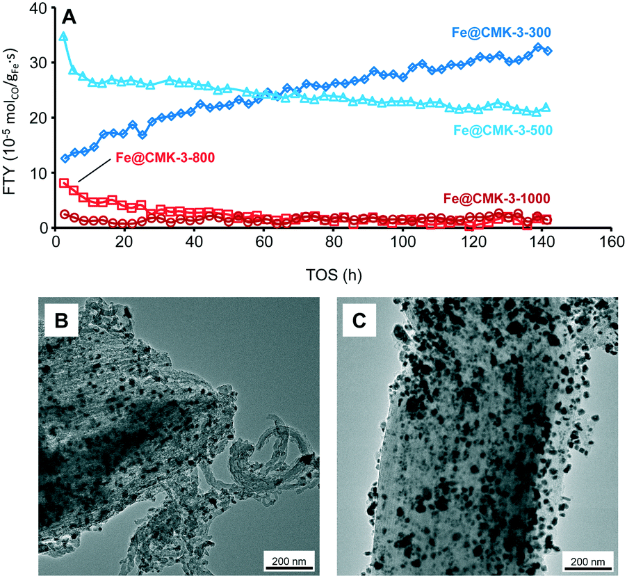 | ||
| Fig. 7 (A) FTY over TOS for sodium/sulfur promoted Fe@CMK-3 catalysts calcined at different temperatures under industrially relevant FTO conditions as well as TEM images of the (B) Fe@CMK-3-300 and (C) Fe@CMK-3-500 catalysts after 140 h TOS. Data obtained at GHSV = 9600 h−1, H2/CO = 2, T = 340 °C, p = 10 bar. | ||
| Catalyst | CO conversion (%) | FTY (10−5 molCO gFe−1 s−1) | Product selectivity (%C in Hydrocarbons) | |||
|---|---|---|---|---|---|---|
| CH4 | C2–C4 olefins | C2–C4 paraffins | C5+ | |||
| Fe@CMK-3-300 | 13.0 | 27.3 | 18.7 | 50.4 | 4.8 | 26.1 |
| Fe@CMK-3-500 | 14.8 | 22.9 | 13.4 | 54.6 | 4.9 | 27.1 |
At 10 bar syngas pressure, the methane selectivity in the formed hydrocarbons remains below 19%C. 50–55%C of the formed hydrocarbons are present as C2–C4 olefins. Due to the efficient promotion of the catalysts with sulfur, olefin/paraffin ratios higher than 10 are achieved due to the preferred chain termination by hydride abstraction instead of hydrogenation. As also observed at 1 bar, slightly more methane is formed by the Fe@CMK-3-300 catalyst as compared to Fe@CMK-3-500. For these catalysts, the C5+ selectivity of 26–27%C remains comparable to the low-pressure measurements. Even under industrially relevant conditions, all catalysts deviate from the ASF distribution in terms of lower C1 and C2 formation (ESI,† Fig. S8). The chain growth probability in the C3–C7 product area decreases with increasing calcination temperature, most likely due to the loss of sodium promoter at higher temperatures. For the catalysts calcined at low temperatures, CO2 selectivities of 40–45%C are measured after 100 h of TOS, resulting from the high water-gas-shift activity of the iron catalysts.
TEM images of the spent catalysts after 140 of TOS (Fig. 7B and C) show that part of the iron particles is present at the external surface of the CMK-3 particles. At the same time, iron nanoparticles are also still numerous within the CMK-3 (ESI,† Fig. S9). The ordered pore structure of the support is still intact after exposure to syngas at 10 bar. Interestingly, significant carbon filament growth occurs for the Fe@CMK-3-300 catalyst but not for the Fe@CMK-3-500 although the initial structure of the catalysts was nearly similar. After 140 h of TOS, the particles at the external surface grow to 20–50 nm in diameter and are present as iron–iron oxide core shell structures due to air exposure prior to TEM analysis.
Summary and conclusions
Ordered mesoporous CMK-3 carbon was used as support for iron-based Fischer–Tropsch to olefins catalysts with sodium and sulfur as promoters. The influence of the calcination and activation conditions on the catalysts structures and their catalytic properties was illuminated. With increasing the calcination temperature from 300 to 1000 °C, carbothermal reduction of the iron oxide particles to metallic iron and iron carbide occurs. At the same time, the metal particles tend to grow and get surrounded by a non-porous graphite shell. For FTO operation at 1 bar, the effect of the activation temperature on the catalytic properties was also studied. An increase of the activation temperature from 350 to 450 °C significantly increases the catalytic activity of the catalysts calcined at low temperatures. In contrast, the change is much smaller for the catalysts obtained at higher calcination temperatures because their activity is determined by the accessibility of the catalytically active sites instead of the presence of reduced iron species.In general, it has been shown that carbon support materials with a well-defined ordered pore structure are useful to study the interplay between synthesis and structure of iron-based FTO catalysts. They provide unique structural properties that facilitate the investigation and interpretation of structural differences on the one hand and allow for the use of specific analysis methods (e.g., SAXS) on the other hand. It has been shown that the interplay between calcination and activation conditions is crucial for the catalytic properties. Many current reports about the synthesis of carbon-supported Fischer–Tropsch catalysts argue with the beneficial effect of encapsulation of iron particles into graphite layers but it should be kept in mind that suchlike structures can negatively affect the catalytic activity by blocking active sites. The encapsulation of unshielded and small iron nanoparticles in a porous carbon matrix in combination with sodium/sulfur promoters is the way of choice towards FTO catalysts with high activity and stability at the same time. For porous carbon supports, the formation of such graphitic layers can be avoided by keeping the calcination temperature at 500 °C or below. Further optimization in terms of promoter levels is necessary for carbon-supported catalysts and will be part of future studies.
Acknowledgements
M. O. acknowledges financial support by the PostDoc program of the German Academic Exchange Service (Deutscher Akademischer Austauschdienst, DAAD). K. P. de J. gratefully acknowledges funding from the European Research Council, EU FP7 ERC Advanced Grant No. 338846. We thank Helen de Waard (Utrecht University, Faculty of Geosciences) for the ICP-OES measurements and Dr. Cedric Gommes (University of Liège, Department of Chemical Engineering) for helpful discussion.Notes and references
- U. Olsbye, S. Svelle, M. Bjrgen, P. Beato, T. V. W. Janssens, F. Joensen, S. Bordiga and K. P. Lillerud, Angew. Chem., Int. Ed., 2012, 51, 5810 CrossRef CAS PubMed.
- F. Jiao, J. Li, X. Pan, H. Li, M. Wei, Y. Pan, Z. Zhou, M. Li, S. Miao, J. Li, Y. Zhu, D. Xiao, T. He, J. Yang, F. Qi, Q. Fu and X. Bao, Science, 2016, 351, 1065 CrossRef CAS PubMed.
- K. Cheng, B. Gu, X. Liu, J. Kang, Q. Zhang and Y. Wang, Angew. Chem., Int. Ed., 2016, 55, 4725 CrossRef CAS PubMed.
- B. Sun, K. Xu, L. Nguyen, M. Qiao and F. F. Tao, ChemCatChem, 2012, 4, 1498 CrossRef CAS.
- H. M. T. Galvis and K. P. De Jong, ACS Catal., 2013, 3, 2130 CrossRef.
- R. Luque, A. R. de la Osa, J. M. Campelo, A. A. Romero, J. L. Valverde and P. Sanchez, Energy Environ. Sci., 2012, 5, 5186 CAS.
- X. Zhou, J. Ji, D. Wang, X. Duan, G. Qian, D. Chen and X. Zhou, Chem. Commun., 2015, 51, 8853 RSC.
- S. Y. Hong, D. H. Chun, J.-I. Yang, H. Jung, H.-T. Lee, S. Hong, S. Jang, J. T. Lim, C. S. Kim and J. C. Park, Nanoscale, 2015, 7, 16616 RSC.
- C. López and A. Corma, ChemCatChem, 2012, 4, 751 CrossRef.
- S. Abelló and D. Montané, ChemSusChem, 2011, 4, 1538 CrossRef PubMed.
- A. De Klerk, Energy Environ. Sci., 2011, 4, 1177 CAS.
- K. Cheng, V. V. Ordomsky, B. Legras, M. Virginie, S. Paul, Y. Wang and A. Y. Khodakov, Appl. Catal., A, 2015, 502, 204 CrossRef CAS.
- S. Li, A. Li, S. Krishnamoorthy and E. Iglesia, Catal. Lett., 2001, 77, 197 CrossRef CAS.
- Z. H. Chonco, A. Ferreira, L. Lodya, M. Claeys and E. Van Steen, J. Catal., 2013, 307, 283 CrossRef CAS.
- H. M. Torres Galvis, A. C. J. Koeken, J. H. Bitter, T. Davidian, M. Ruitenbeek, A. I. Dugulan and K. P. De Jong, Catal. Today, 2013, 215, 95 CrossRef CAS.
- H. M. Torres Galvis, J. H. Bitter, C. B. Khare, M. Ruitenbeek, A. I. Dugulan and K. P. de Jong, Science, 2012, 335, 835 CrossRef CAS PubMed.
- H. M. Torres Galvis, A. C. J. Koeken, J. H. Bitter, T. Davidian, M. Ruitenbeek, A. I. Dugulan and K. P. De Jong, J. Catal., 2013, 303, 22 CrossRef CAS.
- F. Rodríguez-Reinoso, Carbon, 1998, 36, 159 CrossRef.
- H. Xiong, L. L. Jewell and N. J. Coville, ACS Catal., 2015, 5, 2640 CrossRef CAS.
- J. H. Bitter, J. Mater. Chem., 2010, 20, 7312 RSC.
- Y. Cheng, J. Lin, K. Xu, H. Wang, X. Yao, Y. Pei, S. Yan, M. Qiao and B. Zong, ACS Catal., 2016, 6, 389 CrossRef CAS.
- V. P. Santos, T. A. Wezendonk, J. J. D. Jaén, A. I. Dugulan, M. A. Nasalevich, H.-U. Islam, A. Chojecki, S. Sartipi, X. Sun, A. A. Hakeem, A. C. J. Koeken, M. Ruitenbeek, T. Davidian, G. R. Meima, G. Sankar, F. Kapteijn, M. Makkee and J. Gascon, Nat. Commun., 2015, 6, 6451 CrossRef CAS PubMed.
- T. A. Wezendonk, V. P. Santos, M. A. Nasalevich, Q. S. E. Warringa, A. I. Dugulan, A. Chojecki, A. Koeken, M. Ruitenbeek, G. R. Meima, H.-U. Islam, G. Sankar, M. Makkee, F. Kapteijn and J. Gascon, ACS Catal., 2016, 6, 3236 CrossRef CAS.
- W. Chen, Z. Fan, X. Pan and X. Bao, J. Am. Chem. Soc., 2008, 130, 9414 CrossRef CAS PubMed.
- J. Tu, M. Ding, Q. Zhang, Y. Zhang, C. Wang, T. Wang, L. Ma and X. Li, ChemCatChem, 2015, 7, 2323 CrossRef CAS.
- C. Wang, P. Zhai, Z. Zhang, Y. Zhou, J. Ju, Z. Shi, D. Ma, R. P. S. Han and F. Huang, Part. Part. Syst. Charact., 2015, 32, 29 CrossRef CAS.
- H. J. Schulte, B. Graf, W. Xia and M. Muhler, ChemCatChem, 2012, 4, 350 CrossRef CAS.
- M. Casavola, J. Hermannsdörfer, N. de Jonge, A. I. Dugulan and K. P. de Jong, Adv. Funct. Mater., 2015, 25, 5309 CrossRef CAS.
- X. Chen, D. Deng, X. Pan, Y. Hu and X. Bao, Chem. Commun., 2015, 51, 217 RSC.
- A. Taguchi and F. Schüth, Microporous Mesoporous Mater., 2005, 77, 1 CrossRef CAS.
- Y. Yang, L. Jia, B. Hou, D. Li, J. Wang and Y. Sun, Catal. Sci. Technol., 2014, 4, 717 CAS.
- K.-S. Ha, G. Kwak, K.-W. Jun, J. Hwang and J. Lee, Chem. Commun., 2013, 49, 5141 RSC.
- M. Oschatz, W. S. Lamme, J. Xie, A. I. Dugulan and K. P. de Jong, ChemCatChem, 2016, 8, 2846 CrossRef CAS.
- D. Fu, W. Dai, X. Xu, W. Mao, J. Su, Z. Zhang, B. Shi, J. Smith, P. Li, J. Xu and Y.-F. Han, ChemCatChem, 2015, 7, 752 CrossRef CAS.
- A. C. J. Koeken, H. M. Torres Galvis, T. Davidian, M. Ruitenbeek and K. P. De Jong, Angew. Chem., Int. Ed., 2012, 51, 7190 CrossRef CAS PubMed.
- E. de Smit and B. M. Weckhuysen, Chem. Soc. Rev., 2008, 37, 2758 RSC.
- H. M. Torres Galvis, J. H. Bitter, T. Davidian, M. Ruitenbeek, A. I. Dugulan and K. P. de Jong, J. Am. Chem. Soc., 2012, 134, 16207 CrossRef CAS PubMed.
- K. Cheng, M. Virginie, V. V. Ordomsky, C. Cordier, P. A. Chernavskii, M. I. Ivantsov, S. Paul, Y. Wang and A. Y. Khodakov, J. Catal., 2015, 328, 139 CrossRef CAS.
- J.-S. Lee, S. H. Joo and R. Ryoo, J. Am. Chem. Soc., 2002, 124, 1156 CrossRef CAS PubMed.
- P. Munnik, P. E. de Jongh and K. P. de Jong, Chem. Rev., 2015, 115, 6687 CrossRef CAS PubMed.
- C. J. Gommes and B. Goderis, J. Appl. Crystallogr., 2010, 43, 352 CAS.
- C. J. Gommes, G. Prieto, J. Zecevic, M. Vanhalle, B. Goderis, K. P. de Jong and P. E. de Jongh, Angew. Chem., Int. Ed., 2015, 54, 11804 CrossRef CAS PubMed.
- C. J. Gommes, G. Prieto and P. E. de Jongh, J. Phys. Chem. C, 2016, 120, 1488 CAS.
- M. C. Mangarella, J. L. Ewbank, M. R. Dutzer, F. M. Alamgir and K. S. Walton, Carbon, 2014, 79, 74 CrossRef CAS.
- J. Xie, H. M. Torres Galvis, A. C. J. Koeken, A. Kirilin, A. I. Dugulan, M. Ruitenbeek and K. P. de Jong, ACS Catal., 2016, 6, 4017 CrossRef CAS PubMed.
Footnote |
| † Electronic supplementary information (ESI) available: Physisorption data of the pristine CMK-3 support, TEM images of fresh and spent catalysts, details of catalytic data at 1 and 10 bar, physisorption and SAXS data of the spent catalysts, Mössbauer spectra and corresponding fitting data. See DOI: 10.1039/c6cy01251e |
| This journal is © The Royal Society of Chemistry 2016 |