
 Open Access Article
 This Open Access Article is licensed under a
 Creative Commons Attribution 3.0 Unported Licence
An effective modular process for biodiesel manufacturing using heterogeneous catalysis
Alexandre C.
Dimian
* and
Gadi
Rothenberg
Van 't Hoff Institute for Molecular Sciences, University of Amsterdam, P.O. Box 94157, 1090GD Amsterdam, The Netherlands. E-mail: a.c.dimian@gmail.com; g.rothenberg@uva.nl
First published on 27th April 2016
Abstract
We present an innovative reaction set-up and process for biodiesel manufacturing by heterogeneous catalysis. This process has two key advantages over the state-of-the-art process: it enables a variable reaction time and easy catalyst switching/replacement. The process principle presented here is generic for liquid-phase reactions requiring long residence times, where conventional fixed-bed column reactors offer little flexibility. This is especially important when one switches between feedstocks or when the catalyst activity declines over time. Biodiesel manufacturing is a highly relevant example, because the reactor performance depends on the feedstock nature and composition. The concept is demonstrated in a scaled-down continuous laboratory reactor, keeping a similar reaction time and comparable heat and mass transfer to a large-scale process by optimising the reactor dimensions, fluid velocity and catalyst pellet size. We then provide the design of the large-scale process, which consists of serpentine-type plug flow reactors assembled as vertical tubes filled with catalysts. The reactor productivity can increase significantly by reducing the catalyst pellet size. A switching system allows connecting/bypassing the tubes and easy catalyst replacement. The reactor can be employed in a two-stage reaction technology, or in a one-stage reaction combined with membrane separation. Production capacity can be scaled-up simply by adding parallel modules. The versatility and ease of application make this catalytic process concept suitable for low-cost mobile biodiesel production plants.
Introduction
Mankind's short-term interest in biofuels and alternative energy sources might be affected by disorders in the spot price of crude oil, but in the long-term we will have to switch from fossil carbon sources to renewable ones. Biomass holds the key to the transition to a low-carbon economy, as it is widely available and renewable on a human timescale. Indeed, biorefineries will play an important role in any future scenario of sustainable energy management.1 Thus, developing new processes for converting biomass efficiently into fuels and chemicals should be a top priority.2Biodiesel is a case in point. Today, two main types of compatible diesel fuel are commercially produced in a large scale: fatty acid methyl esters (FAME) and hydroprocessed esters and fatty acids (HEFA). Following the US National Biodiesel Board and some experts,3 the term biodiesel refers primarily to FAME, made mostly by the transesterification of triacylglycerides (TAG) and/or by the esterification of fatty acids (FA). Biodiesel primary feedstocks can be vegetable oil crops, such as rapeseed (canola), sunflower, soy and palm (first generation), or preferably waste lipid materials and non-edible vegetable oils, such as jatropha, camelina and ricinus (second generation). Future resources with high potential are algal biomass and the fermentation of carbohydrate wastes to lipids by special yeasts (third generation).4
HEFA fuel can be made by the hydrogenation of all lipid feedstock types. Note that HEFA should be integrated into a petro-refinery environment to ensure the availability of cheap hydrogen, a fluid catalytic cracking (FCC) facility and suitable separation equipment. Since collecting waste oil in large amounts raises logistic problems and costs, the most economical feedstock for HEFA remains shipping vegetable oil from remote plantations (e.g. palm oil), raising questions about its overall sustainability. HEFA is designated as a “green biodiesel” by some commercial producers.
Besides bioethanol, biodiesel is one of the two top renewable fuels. Following the last report of the Renewable Energy Network for the 21st Century (REN21), the annual world biodiesel production rose to more than twelve times from 2004 to 2014 to about 30 billion litres, which represents a share of 23% from the global biofuels. HEFA was about 3% at 4 billion litres. Europe produced 11.5 billion litres (40%), while USA produced 4.7 billion litres (16%). Rapid growth is expected in the next years from South Asia, South America and African countries.5
The sustainability of biofuels is a moot point. Among the assessment criteria, the most important issues are the greenhouse gas (GHG) impact, food security, indirect land use change (ILUC), socio-economic development and energy independence. Regarding the second aspect, there is no clear evidence that the biofuel market threatens the food supply chain. For example, in Europe, the crops for biofuels, mostly biodiesel, use only 1% of the agricultural land.5 Moreover, reducing GHG with respect to fossil fuels is considered by most analysts as the key factor for sustainability. The GHG assessment performed by national and international agencies follows at present the well-to-wheel LCA procedures. The model usually includes emissions from feedstock cultivation (fuels and fertilizers), transportation, and the fuel production process.5–7 Results typically depend on the local conditions. For biodiesel, the GHG reduction varies between 30 and 90% (excluding ILUC).8 The upper level is attributed to waste and non-edible oils, the mid level to efficient energy crops, while the low level refers to some crops issued from non-sustainable farming. The most ambitious sustainability targets are applied in Europe following the Renewable Energy Directive (RED).6 The GHG threshold in 2015 for biofuels was set at 35% with respect to the reference value of 83.8 g of CO2-eq MJ−1, which should increase to 50% in 2017 and 60% in 2018. In USA, the EPA-RFS2 regulation sets the GHG reduction target at 20% for conventional renewable fuels, and at 50% for advanced renewable fuels.9 These rules shall stimulate the progress in technology and the advent of new sustainable feedstock sources.
Note that sustainable biodiesel requires less GHG from the manufacturing process too. Adopting the technology of heterogeneous catalysis, which offers substantial savings in equipment, energy, and materials, can greatly help in achieving this goal. Another step forward would be extending this approach to small (mobile) and medium-capacity plants via a new reactor technology, as we propose here.
Biodiesel production by homogeneous catalysis and batch processes dominates today's market. It uses a relatively simple technology, easily adaptable to different feedstocks, and suitable for small and medium-capacity plants. Among recent progress in technology, the most potent has been the employment of solid base catalysis.10 This can reduce substantially both the capital and operation costs, delivering high-purity glycerol as a bonus. The French company AXENS developed the Esterfip™ process based on a zinc aluminate catalyst.11–13 The preferred feedstock is vegetable oil with low free fatty acid (FFA) and water contents. This process was implemented in large-scale plants in France, Malaysia, Sweden and the US. Six plants were built up to 2012 with a total capacity topping 1.2 Mtpa. These plants use fixed-bed adiabatic tower reactors with the catalyst split into two sections, and provided with devices for ensuring a homogeneous mixture and plug-flow profile.13 The design and operation of such reactors is constrained by the nature and the quality of the feedstock. Catalyst robustness is a key issue here, since the process uses large amounts of catalyst. A long time-on-stream is needed, preferably over six months. Furthermore, compensation of the catalyst deactivation by raising the temperature is limited, due to the risk of glycerol decomposition.
Thus, the challenge of the catalytic process is dealing with diverse industrial-grade feeds and converting them efficiently into a product following strict quality specifications, as defined by EN14212 and ASTM D6751. In 2006, our group published the first example of biodiesel synthesis from FFA using heterogeneous catalysis,14 extending this later to various feeds and process options.15,16 Here we present a solid catalyst process combined with an innovative reactor design that offers flexible reaction times and easy catalyst change upon deactivation. Importantly, this system is modular, and therefore suited for smaller scale and mobile production plants. This makes it compatible with the requirements of the biorefinery concept, as it can valorise locally available resources with low investment and operation costs.
Solid catalyst technology
The manufacturing of biodiesel by heterogeneous catalysis has major economic benefits compared to the traditional homogeneous catalysis. As shown in Fig. 1, the main reason is the suppression of operations generating large amounts of wastewater (except during feedstock pretreatment), namely the catalyst removal by acid/base neutralisation reactions, washing of FAME and glycerol, as well as methanol recovery by distillation of aqueous solutions. There is no salt waste, and catalyst consumption drops dramatically. In the homogeneous process, glycerol has a maximum purity of 85% after expensive separations, while the heterogeneous process delivers glycerol that is >98% pure, a valuable product. In addition, the continuous operation is intrinsically more efficient than batchwise.17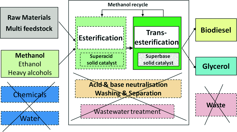 | ||
| Fig. 1 The advantage of biodiesel manufacturing by a heterogeneous base catalyst. | ||
Heterogeneous catalysis may be applied both to low and to high FFA oils. In the latter case, preliminary esterification with methanol is necessary, which can be performed by employing a solid acid catalyst, such as Amberlyst-type ion-exchange resins.3,17 The small amounts of water formed can be removed simply by adsorption. Higher FFA lipids, such as animal fat and industrial greases, can be treated in a reactive distillation device.18
Benchmark calculations performed at Yellowdiesel B.V19 using a factorial method based on the purchasing cost of basic equipment20 indicate that for a plant with a processing capacity of 100 ktpy, the capital expenses (CAPEX) can drop by 40–60% since less equipment and a more compact design are needed. In addition, the operating expenses (OPEX) can fall by 40–50% mainly by deleting energy intensive operations involving water, and also due to the significant savings in the catalyst cost. Note that the higher temperature in the reaction stage, around 200 °C, should not penalise the energy consumption if adequate heat integration measures are taken.17,20 These include feed preheating by a reactor effluent and employing thermal fluids instead of steam. Similar economic benefits were reported by comparing homogeneous and heterogeneous biodiesel processes by simulation with Hysys.21
Fig. 2 shows a conceptual flowsheet inspired by the original Esterfip™ process.11–13 Methanol and vegetable oil, which are pumped at higher pressure, heated up and mixed, enter the first adiabatic transesterification reactor (R-1). The preferred operation conditions are a pressure between 40 and 70 bar, a temperature from 200 to 220 °C, a liquid hourly space velocity (LHSV) of 0.5–1 h−1, and a MeOH![[thin space (1/6-em)]](https://www.rsc.org/images/entities/char_2009.gif) :oil weight ratio of 1:2. The catalyst used is extrudates of 3 mm diameter. After pressure reduction, the outlet mixture is flushed out to remove the excess methanol and to allow easy separation of glycerol by decantation, which is needed for shifting of the chemical equilibrium. The ester phase enters a second reaction stage (R-2) similar to the first step, so methanol make-up and feed preheating are needed. In the first stage, the conversion may increase up to 90–93%, while in the second stage, it may be up to 99.5%. The final FAME mixture is subjected to methanol removal by two-stage evaporation, followed by glycerol separation by decantation. The excess methanol is recycled after the distillation of glycerol and FAME streams.
:oil weight ratio of 1:2. The catalyst used is extrudates of 3 mm diameter. After pressure reduction, the outlet mixture is flushed out to remove the excess methanol and to allow easy separation of glycerol by decantation, which is needed for shifting of the chemical equilibrium. The ester phase enters a second reaction stage (R-2) similar to the first step, so methanol make-up and feed preheating are needed. In the first stage, the conversion may increase up to 90–93%, while in the second stage, it may be up to 99.5%. The final FAME mixture is subjected to methanol removal by two-stage evaporation, followed by glycerol separation by decantation. The excess methanol is recycled after the distillation of glycerol and FAME streams.
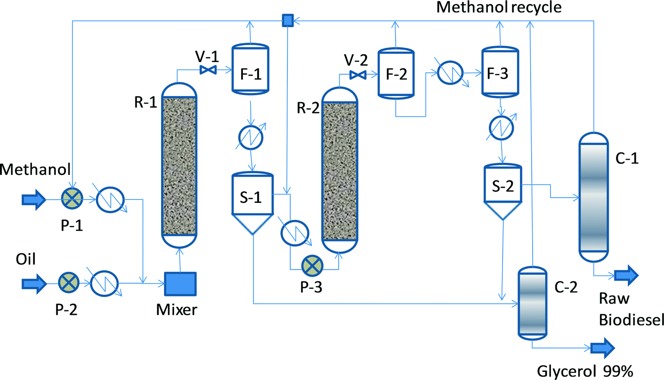 | ||
| Fig. 2 Conceptual flowsheet for FAME manufacturing by heterogeneous catalysis. | ||
Note that in the above process the purity specifications of the biodiesel, namely with respect to residual TAG, should be achieved almost completely after the reaction section. Thus, the reactor design should provide sufficient oversizing for dealing with feedstock variability, catalyst deactivation, and other disturbances. When using the zinc aluminate catalyst, the water content of the feedstock should be limited to 500 ppm, and the FFA acidity index should be lower than 10 mg of KOH per g of oil.11
A shortcut calculation brings a useful insight into the reactor design. Let us consider a production rate of 150 ktpa, 8000 hours of annual operation, 90% yield, and a 600 kg m−3 density for the oil/methanol mixture. It results in a reactor volume of 74.4 m3. This value will be confirmed later in this paper by more accurate computations based on detailed kinetics.26 If we assume a reactor diameter of 2.4 m, the height of the cylindrical part hosting the catalyst should be at least 16.5 meters. The fictive fluid velocity, based on the empty cross section, would be about 3.2 mm s−1 or 11.5 m h−1. In addition, the plug flow profile requires adequate internals for mixing and redistribution, as well as for catalyst handling. Designing such a unit in practice is further complicated by the uncertainty regarding the kinetic behaviour of the feedstock and by catalyst robustness.
The Esterfip™ catalyst was discovered by Stern et al.22 in 1999 and improved in subsequent patents.23,24 The generic formula is ZnAl2O4·xZnOyAl2O3 in which x and y are numbers in the range from 0 to 2. Recent developments described a spinel-type catalyst as robust and efficient because of very little zinc leaching.25,26 However, the robustness under industrial conditions was not disclosed.
The success of Esterfip™ led to intensive research in the field of solid base catalysts. Comprehensive reviews were published.27–29 Mixed metal oxide catalysts, namely hydrotalcites, showed good activity at higher temperature and reasonable reaction time.30–34 Note that dolomites, with a comparable structure to hydrotalcites, could be used as an abundant low-cost catalyst.10,35 Among the latest developments, one can cite the double-metal cyanide Fe–Zn catalyst developed by the Indian Pune Laboratory,36 which proved to be successful both for the esterification and transesterification of oils containing a significant amount of FFA. A process using this catalyst was implemented as the ENSEL® process37 by the American company Benefuel. Despite abundant research, the literature study indicates that the synthesis of an efficient and robust solid catalyst for the transesterification of TAG remains a considerable challenge.
Experimental: a miniplant for biodiesel manufacturing
When dealing with solid catalysts for liquid-phase reactions, batch micro-reactors are used in most academic research studies for preliminary investigation. The catalyst is usually employed as powder. This method focuses on chemistry by eliminating mass and heat transfer resistances. The time evolution of concentrations in a batch reactor mimics the concentration profiles along the length of an ideal plug flow reactor (PFR). However, batch experiments are not sufficient for industrial application. The investigation should use an experimental device offering hydrodynamic similarity close to the industrial implementation. Accordingly, the pellet size should be adapted to the internal and external mass and heat transfer. Appendix 1 presents a simple method for designing a laboratory PFR by employing similarity principles. It is important to note that the scale-down in terms of the diameter and length is very different. Typically the diameter ratio could be over 100:1, while the length ratio only up to 10:1.
With these elements in mind, we designed and built a miniplant for manufacturing commercial grade biodiesel by heterogeneous catalysis (see schematic in Fig. 3). The chemical reactor is a spiral coil from SS 316 of ID 6 mm and OD 9 mm, with lengths of 2.4 and 3.6 m, filled with 0.8 mm catalysts. A 1 m silica gel pre-column is used for feed drying. The reactor is hosted in an electrical oven (Heraeus; Germany) with an internal size of 60 × 55 × 55 cm. The electronically regulated temperature can rise up to 250 °C. Oil and methanol are fed through metering membrane pumps (LEWA; Germany) with a maximum flow rate of 250 ml h−1 and a pressure of 50 bar. The oil/methanol mixture is preheated and homogenised before the reaction by passing it through a static mixer. A central element of the plant is the backpressure device, which has to ensure a single liquid phase well below the saturation point (bubble point). For this reason, the pressure is set at a minimum 5 bar higher than the methanol vapour pressure, namely in the range of 35–50 bar, corresponding to reaction temperatures from 180–210 °C. The above set-up is capable of ensuring a variable reaction time, in general an LHSV of 0.5–2 h−1, by connecting several reaction coils in series, or by adjusting the feeds of reactants. Flushing the reactor with a methanol flow is used both for starting-up and shutting down the plant.
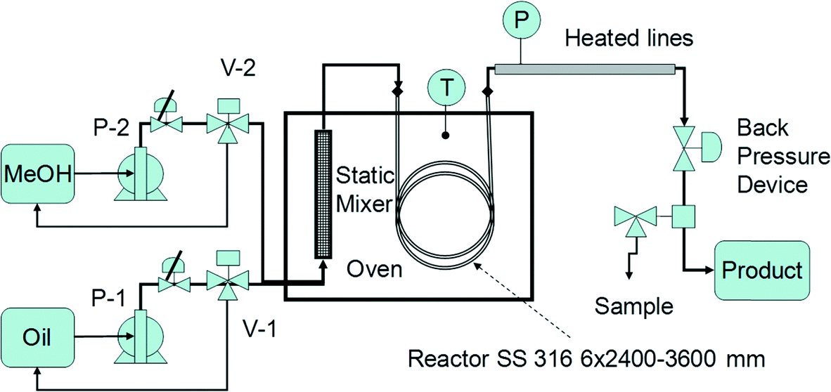 | ||
| Fig. 3 Schematic of a miniplant for continuous biodiesel manufacturing by heterogeneous catalysis. | ||
The analytical equipment was a Thermo Science GC apparatus with a PVT/SSL backflush injector and an FID equipped with a Restek-Stabilwax column, which allowed accurate identification of methyl esters from C14 to C22. In view of GC analysis, pure C14 was added in the feed as 10 vol% with respect to oil.
The above described miniplant was used for investigating potential industrial feedstocks. Pretreated feedstocks, such as rapeseed, jatropha and frying fat, were supplied graciously by the biodiesel producer Solarix B.V. Amsterdam, while sunflower, soya, and peanut were commercial vegetable oils. To prevent any influence of the impurities on the kinetic behaviour, the feedstock was additionally cleaned by treatment with a 40 wt% phosphoric acid solution, neutralised, decanted, washed with distilled water and dried under vacuum. The experiments reported here employed a MgAl hydrotalcite catalyst supplied by Eurosupport B.V. Netherlands as cylindrical pellets of 1.5 × 3 mm. The catalyst was crushed, sieved and flushed with nitrogen to get a uniform size of 0.8 mm free of fines. The hydrotalcite catalysts have, as a remarkable feature, a layered-type arrangement, which is advantageous for the internal diffusion of bulky TAG molecules, as well as for the extraction of the reaction products. The catalyst structure was characterised by employing a Thermo Fischer Scientific mercury porosimeter, and is reported elsewhere.38 The key results are: a bulk density of 1.04 g cm−3, a void volume of 680 mm3 g−1, an accessible porosity of 58%, an internal area of 90 m2 g−1, an average pore diameter of 25 nm, a median pore diameter of 63 nm, and a maximum pore diameter of 275 nm. For comparison, a catalyst used in the Esterfip process25 had a specific surface area of 160 m2 g−1 and mesopores ranging between 9 and 100 nm. The availability of very large pores favours the internal diffusion of the bulky TAG molecules, and supports complex surface reactions for converting TAG to FAME. In addition, the talcite catalysts can be produced from low-cost clay materials. The regeneration can take place by simple calcination at temperatures between 500 and 600 °C. The waste catalyst is a nontoxic material that can be used as a construction filler.
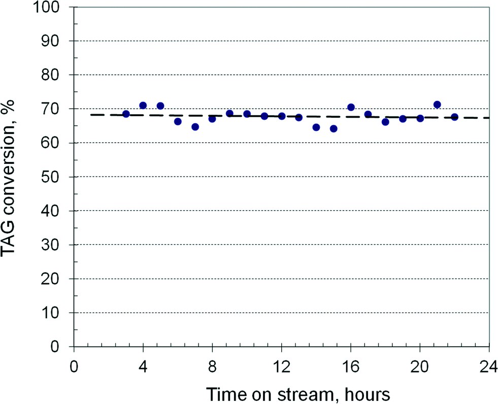
Fig. 4 shows the TAG conversion over a 24 h TOS in a reactor of 3600 mm length filled with 103 ml of catalyst at 190 °C and 37 bar using rapeseed oil as feed. The methanol/oil ratio is 0.55, with a combined feed of 175 ml h−1. It results in an LHSV of 1.72 h−1, or a residence time of 35 min, with a fictive velocity of 1.7 mm s−1. The conversion is practically constant around 68% indicating unchanging catalyst activity. After methanol evaporation and glycerol decantation, the transesterification can be continued in a second stage, where the conversion can be pushed to >90%, and then in a third run to over >98%. By decreasing the LHSV to about 1 h−1, the conversion in the first run can rise to about 90%, requiring only two transesterification stages. The catalyst activity remains nearly constant over several days with runs of 10 hours, the reactor being flushed at shut-down with methanol for a minimum of twice the residence time. However, at a longer operation time, the activity declines slowly. The catalyst can be regenerated by simple calcination in an electrical oven at 550 °C, recovering at least 90% of its activity. This behaviour in terms of activity and stability is close to the results reported recently with a hydrotalcite catalyst in a fixed-bed reactor over 55 h TOS.39
 | ||
| Fig. 4 Continuous transesterification run in a laboratory fixed-bed reactor. | ||
Results and discussion
The influence of feedstock on the reactor performance
The feedstock for biodiesel shows a large compositional variation. Table 1 illustrates a typical oil composition expressed as the amounts of saturated and non-saturated fatty acids. The data for jatropha correspond to South American crops.40 As indicated, saturated C16 and C18 fatty acids dominate in palm kernel oil, tallow and frying fats. Rapeseed is richer in mono-unsaturated (MUS) oleic acid. Peanut and soya oils have large amounts of poly-unsaturated acids (PUS) such as C18:1 and C18:2, but soya contains also a substantial amount of C18:3. Jatropha oil is richer in C18:2, together with substantial amounts of C16:0 and C18:1. Table 1 displays also the ratio R of unsaturated/saturated fatty acids, which varies from 0.16 for palm kernel oil to 13.3 for rapeseed oil. The spatial conformation of triglyceride molecules is very diverse, resulting from the shape of fatty acids. This can evolve from straight chains to more or less squeezed/bent shape molecules. Accordingly, the diffusion properties of triglyceride molecules through porous solid catalysts should be very different too.| Feedstock type | Fatty acid type composition (% weight) | ||||||
|---|---|---|---|---|---|---|---|
| C16:0 | C18:0 | C20+ | C18:1 | C18:2 | C18:3 | R | |
| Palm kernel oil | 80 | 6 | 0 | 12 | 2 | 0 | 0.16 |
| Frying fat | 50 | 7 | 0 | 35 | 8 | 0 | 0.75 |
| Pork tallow | 10 | 41 | 0 | 42 | 3 | 4 | 0.96 |
| Jatropha | 22 | 6 | 1 | 22 | 48 | 1 | 2.45 |
| Peanut oil | 10 | 4 | 5 | 40 | 41 | 0 | 4.26 |
| Soya oil | 10 | 4 | 0 | 25 | 51 | 10 | 6.14 |
| Rapeseed | 4 | 3 | 0 | 65 | 20 | 8 | 13.29 |
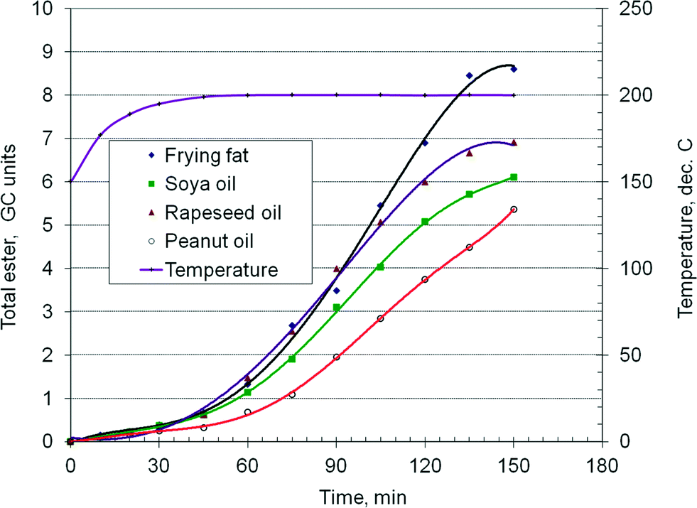
As demonstrated in a previous paper,38 when using a hydrotalcite catalyst, there is a relation between the chemical composition of the feedstock, namely the ratio of saturated to non-saturated fatty acids, and the kinetics of the transesterification reaction, with important consequences for the chemical reactor design. Fig. 5 presents the time–conversion curves of four typical feedstocks: frying fat, soya, peanut and rapeseed oils. The ordinate represents the total ester concentration in GC units. The experiments were conducted in batch mode in a high pressure stirred autoclave of 150 ml, at 190 °C and 40 bar. A typical experiment involves 100 ml of oil, 25 ml of methanol, 10 ml of tetradecane as internal standard and 14 g of catalyst. It can be observed that the kinetic behavior of the oils is notably different. The first 45 minutes is the heating period. The slope of the curves shows that the frying fat exhibits the fastest reaction rate, followed by the rapeseed oil, soybean and peanut oils, with the last one having a somewhat longer sluggish period. If the linear range of the isothermal data is only considered, it gives the relative reaction rate of frying fat/rapeseed/soy/peanut as 1.6/1.26/1.17/1.0. These results suggest that the chemical nature of the feedstock may have an influence on the kinetics of the transesterification reaction. Faster reaction rates should be expected for a higher content of saturated fatty acids, while the opposite should happen for unsaturated oils. Indeed, the behaviour of frying fat (R = 0.75) seems to confirm this assumption. However, the rapeseed oil (R = 13) reacts somewhat faster than the soy oil (R = 6), while the peanut oil (R = 4) is the slowest. Table 1 shows that the rapeseed oil has a higher C18:1 oleic TAG content, the soy oil has a higher C18:2 linoleic TAG content, while the peanut oil contains a notable amount of C20+ TAG. These results suggest that there are differences in the kinetics among the unsaturated TAG too.
 | ||
| Fig. 5 Comparative experiments in a batch reactor. | ||
The above kinetic behaviours may be explained by the steric hindrance effects on pore diffusion, as well as by interactions between the unsaturated bonds and the catalyst surface. The effective diffusion properties of the TAG depend strongly on the chain's shape. Thus, saturated TAG exhibiting “straight” chains, such as palmitic C16:0 and stearic C18:0, should diffuse easier inside the planar multi-layer structure. The cis-C18:1 oleic acid chains (Ω-9) show a “bent” shape and slower diffusion. The C18:2 linoleic (Ω-6) and C18:3 α-linolenic chains (Ω-3) show a “hook” shape that is even more likely to give steric hindrance. From the surface reaction viewpoint, the poly-unsaturated chains may be slowed down by the hydrogen–catalyst bonds. Very long C20+ chains could give even slower diffusion by bending the molecule to access the reaction site.
A more accurate description of the kinetic effects was obtained by examining the behaviour of the individual fatty acids. Fig. 6 displays the concentration vs. time curves of soya oil transesterification in a batch reactor as described before, by monitoring the formation rate of four groups of esters, namely palmitic plus stearic, oleic, linoleic and linolenic. The methanol/oil ratio was 0.5 w/w or about 15:1 mol mol−1. Due to a large excess of methanol, first order kinetics can be safely assumed and the following relation applies:
| kτ = −ln(1 − X/Xeq) | (1) |
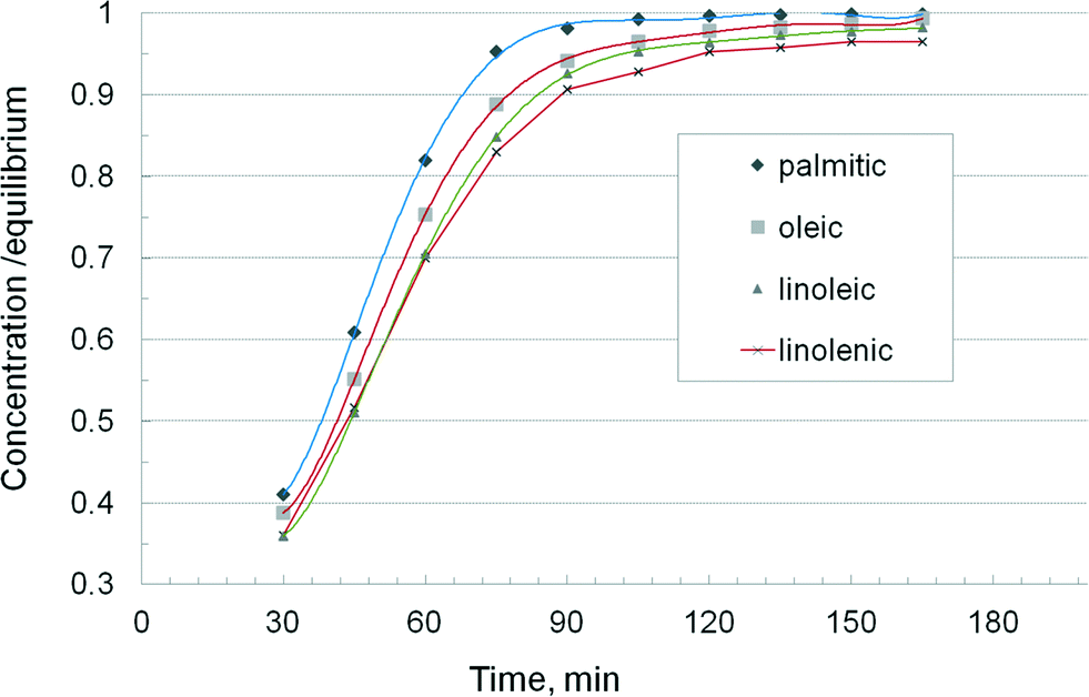 | ||
| Fig. 6 Kinetics of transesterification for individual triglycerides. | ||
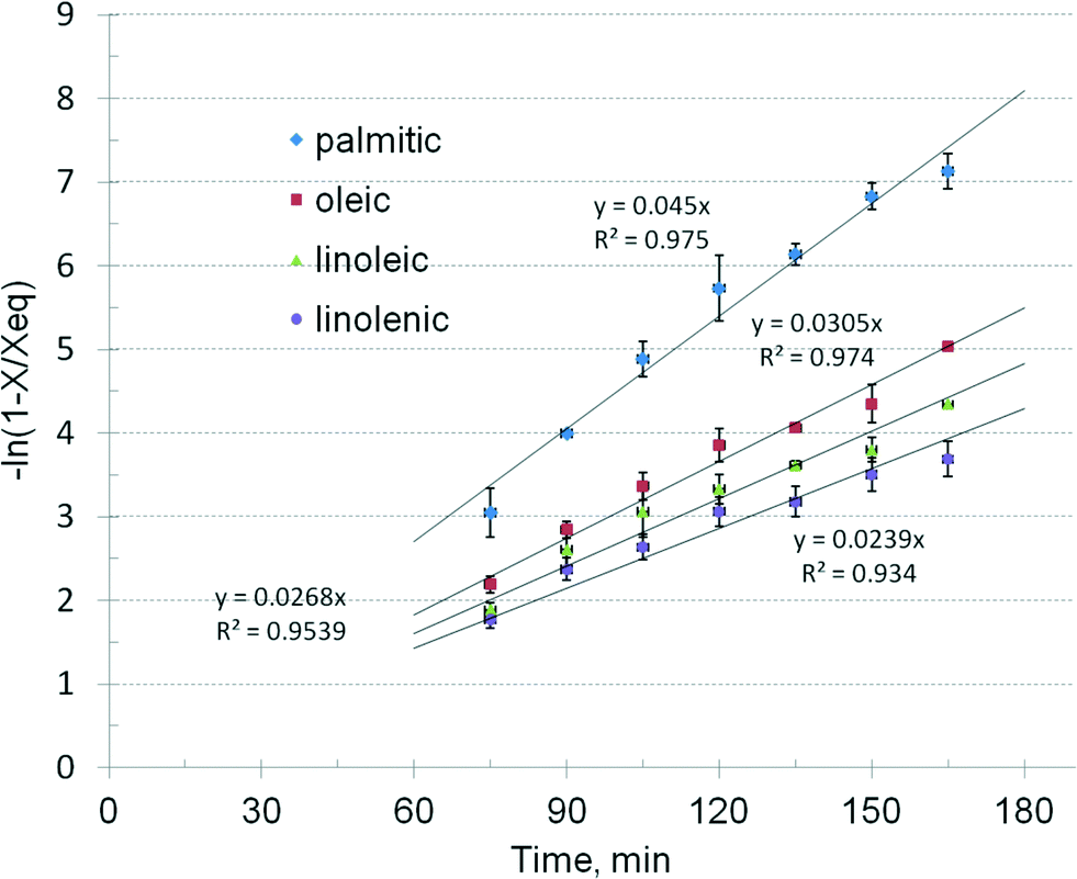 | ||
| Fig. 7 Linear regression of kinetic data for individual triglycerides. | ||
| C16:0 & C18:0 | C18:1 | C18:2 | C18:3 | |
|---|---|---|---|---|
| k, min−1 | 0.045 ± 0.0023 | 0.0305 ± 0.0012 | 0.0268 ± 0.0015 | 0.0239 ± 0.0014 |
| k ratio | 1 | 1.47 | 1.68 | 1.88 |
The results show that the catalytic reaction rate of different TAG depends on the type of fatty acid. Saturated chains such as palmitic and stearic TAG exhibit the highest rate. The oleic TAG reacts about 47% slower, showing that the double bond introduces a significant molecular hindering effect. It is followed by linoleic and linolenic TAG, with additional delays. The question arises if these differences in the reaction kinetics may have practical consequences for the design and operation of biodiesel processes, namely when using feedstock with a different TAG profile.
By using the composition given in Table 1 and the kinetic values from Table 2, average first order constants have been calculated, and then the reaction time for a given conversion was reconstructed. Fig. 8 presents the curves for industrially relevant feedstocks, such as rapeseed, soybean, jatropha and frying fat. Two reference curves were also traced for palmitic (C16:0) and linoleic (C18:2) TAG. The results show again a significant difference in the kinetics. Faster runs are obtained with essential saturated oils, such as kern palm oil and coconut oil, while unsaturated oils, such as rapeseed, soybeans and jatropha, show a slower kinetics, dominated by the presence of oleic and linolenic chains. Frying or tallow fats, having a comparable proportion of saturated and unsaturated TAG, show an intermediate kinetics. The differences between the kinetic behaviour widen with increasing conversion. Rapeseed and soya oils show similar kinetics, which can be explained by the compensating effect of more saturated TAG in the latter. Note that the above computations take into account only the key fatty acids, from C16 to C18. The presence of very large TAG molecules, ignored in this study, and of impurities, which may be trapped in the catalyst structure, might add supplementary slow-down effects on the kinetics of the reaction.
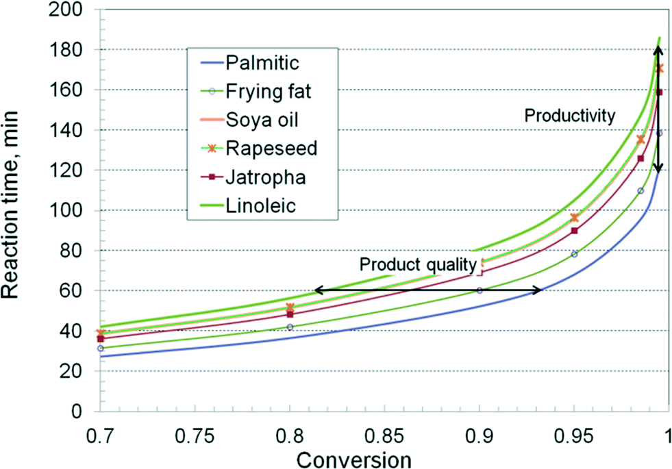 | ||
| Fig. 8 Relation between the chemical nature of the feedstock and the reaction kinetics. | ||
The results reveal two important technological aspects. The first one is about the inter-stage separation of glycerol. For the application of the two-stage technology, the TAG conversion in the first step should be around 90%. Fig. 8 indicates that the necessary time is 60 minutes for frying fat, but 75 minutes for the rapeseed oil. After a one hour–run, the conversion for the rapeseed oil would be only 84%, insufficient to get 98.5% in the second stage. A substantial increase of the reaction time, or a third stage, would be necessary. If the reactor has a limited oversizing capacity, this behaviour becomes problematic. The same troubles occur when the catalyst activity declines. The second aspect is related to productivity. Since a very high conversion is needed to follow quality specifications, this is achieved easier with saturated TAG. Again, when the conversion in the first stage is insufficient, a third or a fourth reaction stage is needed, and as a consequence, the productivity drops drastically.
From the above investigation, it is clear that the reactor design for biodiesel manufacturing by heterogeneous catalysis should provide sufficient flexibility both in ensuring an adaptable reaction time to the feedstock type, and for easier catalyst replacement when the activity falls, by leaching or by contamination. This is the subject of the next section.
An innovative reaction system for catalytic biodiesel manufacturing
Fig. 9 presents the innovative solution we proposed in a patent application.41 The variable reaction time device consists of a serpentine-type plug flow reactor, assembled as vertical tubular segments filled with a solid catalyst. A switching valve system (not shown) is employed for connecting or bypassing the reaction tubes, as well for easy catalyst replacement. The set-up makes use of static mixers. Heating & cooling elements are provided for mixture conditioning before and after the reaction. Energy saving is obtained by using counter-current coupling, such as feed-effluent heat exchangers (FEHE). A liquid thermal agent (Dowtherm, hot oil, etc.) is used as a heat carrier.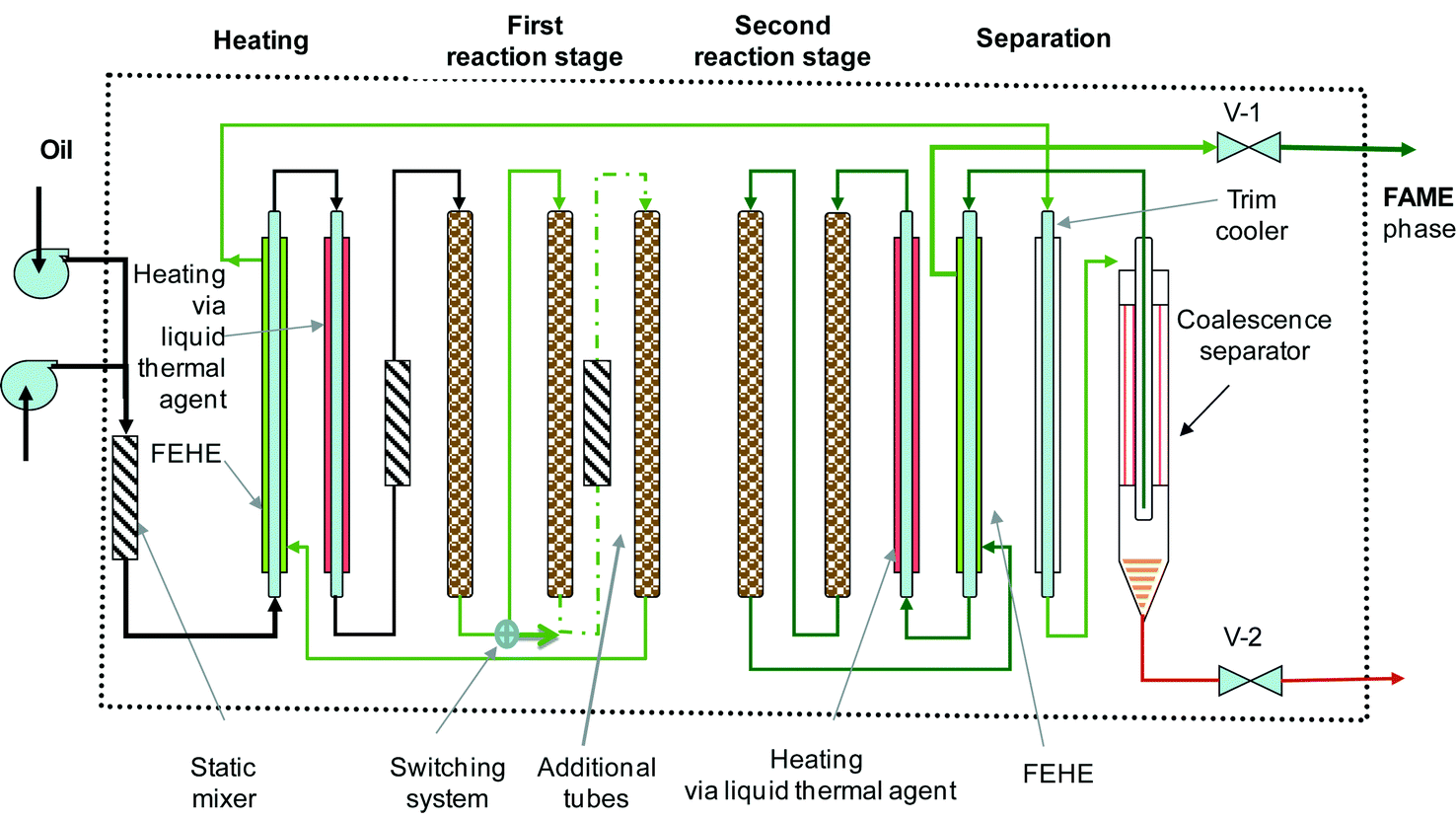 | ||
| Fig. 9 Compact reaction/separation system using a tubular segmented reactor for biodiesel manufacturing. | ||
The transesterification takes place in two stages with an intermediate glycerol removal step. The glycerol separator can be a gravity coalescence separator made up of hydrophobic/hydrophilic materials to accelerate the formation of larger drops,42 or a compact centrifugal device. The final conversion should be higher than 98.5%.
The operation conditions for the hydrotalcite catalyst are a temperature of 180–220 °C, a pressure of 35–70 bar, and an LHSV of 0.5–2 m3 m−3 catalyst h−1. The construction allows adjusting the residence time to the feedstock type and to the catalyst activity by varying the number of the active tubes. Moreover, the scale-up of the plant capacity can be done easily by assembling parallel “reaction boxes”.
Note that the above presented set-up is generic for liquid-phase reactions that need a larger volume, a longer residence time, and making use of a solid catalyst. Double-pipe heat exchangers can ensure effective heat transfer in the zones where this is needed, for re-boosting the chemical reaction.
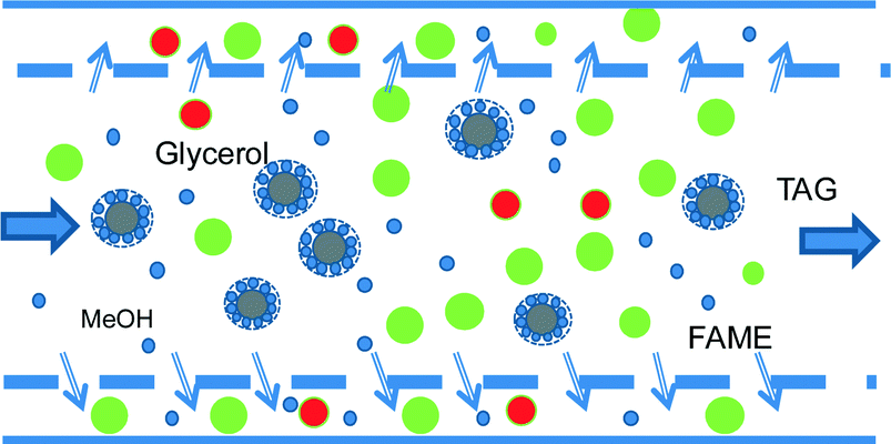
Another innovative solution makes use of only one-step transesterification in a variable reaction time device coupled with membrane separation, which ensures recycling both triglycerides and methanol. Commercially available ultrafiltration and nanofiltration membranes can easily separate small and large molecules under these conditions.43 In biodiesel manufacturing, there are significant differences between the molecules both in size and shape, as well as in the hydrophobic/hydrophilic character. For the relative order of magnitude of the molecule sizes, the kinetic diameter is about 0.4 nm for methanol and 0.6 nm for glycerol. The kinetic diameter of fatty acid alkyl esters depends on the length and character of the hydrocarbon chain, and is generally in the range of 0.8 to 1.5 nm. The size of triglyceride molecules is larger by almost an order of magnitude. However, there is another physical phenomenon that can be exploited for separation, as shown in Fig. 10. Under immiscibility conditions, an emulsion can form, in which the TAG molecules surrounded by methanol are segregated in large particles. This possibility was demonstrated experimentally by the transesterification of canola with methanol; oil droplets of 44 μm mean diameter were formed with a size distribution from 12 μm to 400 μm.44
 | ||
| Fig. 10 Separation of triglycerides by membrane microfiltration. | ||
Fig. 11 shows the conceptual flowsheet. After transesterification and cooling, the well-dispersed outlet mixture (pumping or static mixing device) is submitted to the first separation stage by microfiltration. The TAG molecules remain in the retentate, while FAME, glycerol and methanol pass through to the permeate. TAG are recycled to the catalytic reactor, a drain being provided to prevent accumulation of unreacted oil and impurities. For this separation, commercial ceramic or carbon membranes are suitable with pores in the range of 0.4 to 1.4 μm.44 After remixing, the permeate is subjected to a second membrane separation process, this time by ultrafiltration. FAME and glycerol are immiscible, but glycerol and methanol are miscible. In addition, the diffusion of glycerol through the membrane will be hindered by its higher viscosity. As a result, methanol goes in a large majority in the permeate and is recycled to the reaction, while the FAME/glycerol mixture remains in the retentate and is subjected to separation by decantation or centrifugation. This method may be feasible with ceramic membranes with pores of 0.2 μm, in analogy with experiments separating biodiesel, glycerol and ethanol.45
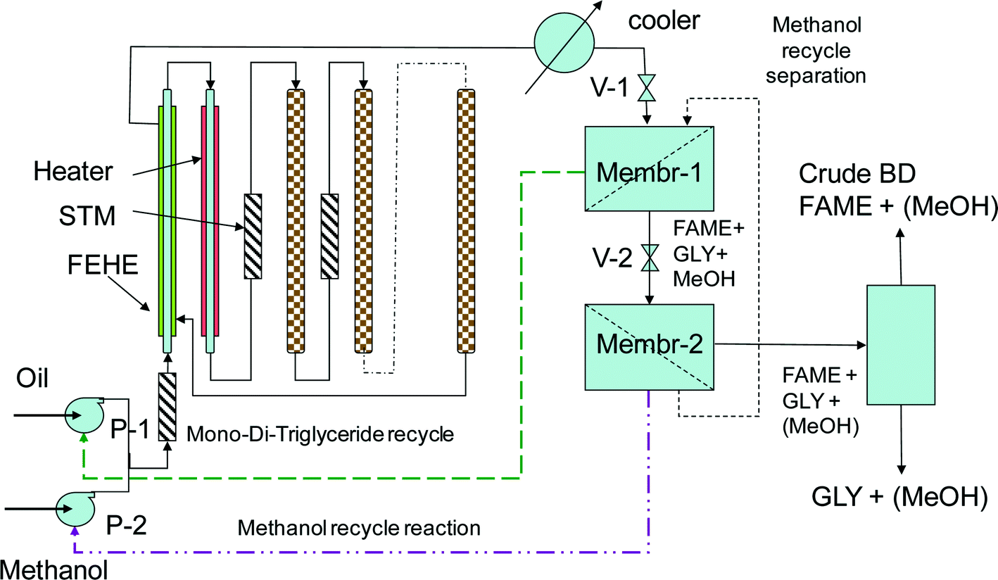 | ||
| Fig. 11 Single-stage reaction using a tubular segmented reactor and membrane separation for biodiesel manufacturing. | ||
As support for the viability of the above approach, we may associate recent research studies regarding membrane reactors for biodiesel working with homogeneous catalysis.46–48 More information on the process intensification aspects of biodiesel manufacturing can be found in a recent monograph.49
Putting in a nutshell, the advantages of this method are:
a. More flexibility in the reactor operation. The TAG conversion could be in a wide range between 70 and 90%, while high recovery of TAG and methanol in recycles is not required. This time the quality of biodiesel is decided in the separation section, not in the reaction steps, as previously described.
b. Important energy savings can be obtained by recycling most of the methanol in the liquid phase and not by distillation. Only a limited amount of methanol carried with FAME and glycerol need to be recovered by distillation. Conversely, a larger methanol/oil ratio could be employed for boosting the transesterification by internal recycling.
c. The problem of soap formation, with a very negative effect on the operation costs,50 can have an efficient solution.
d. Better specifications of the end-products are obtained.
e. The pressure differences that drive the membrane process are available from the initial stream pressure.
f. The design and operation parameters can be optimised on a wide scale as a function of the reaction parameters and membrane characteristics.
As an example, we present a comparative design of a chemical reaction system with an intermediate glycerol separation step for the Esterfip process employing a ZnAl2O4 catalyst. Table 3 shows the kinetic data adapted from Allain et al.26 considering an overall efficiency of 0.25 that is multiplied to the pre-exponential factors of the original rate equations. This is necessary since the industrial reactors employed extrudates of 3.0 mm while the lab reactor was filled with grains of 0.4 mm. Glycerol is completely removed after the first reaction step and no supplementary MeOH is added in the second stage. The final product is free from methanol and glycerol.
| Reaction | k 0, m6 kg of cat kmol−1 s−1 | E a, kJ kmol−1 | K eq | |
|---|---|---|---|---|
| 1 | TAG + MeOH ↔ DAG + FAME | 3.15 × 10 | 64600 |
51.2 |
| 2 | DAG + MeOH ↔ MAG + FAME | 2.22 × 10⁻³ | 31800 |
53.1 |
| 3 | MAG + MeOH ↔ GLY + FAME | 3.18 × 10⁻⁵ | 17000 |
12.2 |
A Matlab® simulation using a pseudo-homogeneous concentration-based model was constructed. The key assumptions are:
1) Plug-flow profile, no maldistribution of the reaction mixture and no radial dispersion due to a suitable hydraulic design and upward flow;13
2) Negligible external resistance to diffusion due to fast mass transfer compared with internal diffusion and reaction due to long residence time;
3) Negligible temperature gradients due to small heat of reaction;
4) Internal diffusion of the TAG and FAME molecules is a rate controlling process via the overall efficiency mentioned earlier.
These assumptions are supported by a comprehensive 2D simulation model of an industrial reactor.51 The key role of the internal diffusion on the kinetics is emphasized by the present study too. Thus this model allows getting useful insights into the catalytic reactor technology, such as the relation between the residence time, catalyst activity and final product specifications.
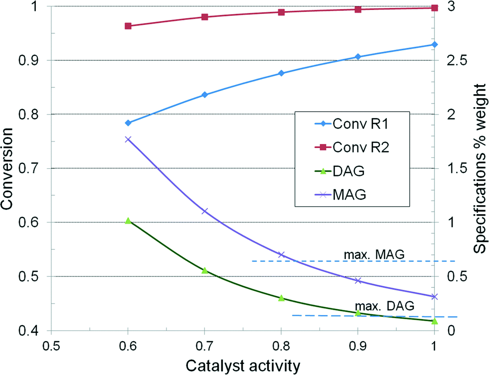
Following the EN14214 minimum specifications, the contents are as follows: ester content 96.5%, triglycerides TAG 0.2%, diglycerides DAG 0.2%, and monoglycerides MAG 0.7%. The reactors are identical with a diameter and length of 2.4 and 16 m, respectively, with a volume of 72.35 m3 each. The feed consists of 300 kmol h−1 methanol and 25 kmol h−1 trioleine, which gives a combined feed of 31745 kg h−1, at a molar ratio of 12 or 0.434 weight ratio. The temperature is set constant at 190 °C. If a mean density of 600 kg m−3 is considered, it gives an LHSV of 0.73 m3 m−3 catalyst h−1. The mean fluid linear velocity in the reactor is around 3.25 mm s−1, which should ensure a plug flow profile and an acceptable mass transfer rate.
Fig. 12 illustrates the dependence of reactor conversion as a function of catalyst activity, as well as the evolution of product specifications. In the base-case, the final product rate is 22260 kg h−1 and accordingly the productivity over the two reactors is 153.85 kg m−3 h−1 or 3692 kg m−3 per day. The conversion in the first reactor should be over 88% to ensure an in-specs final product. If it drops below 80%, then the product is off-specs. Since the reactor volume is fixed, restoring the specifications can be done only by raising the temperature, for example from 190–205 °C when the activity falls to 0.6, or by reducing proportionally the throughput. The rise of the reaction temperature is technologically constrained to 15–20 °C, which implies more energy consumption. Changing an exhausted catalyst needs plant shut-down and throwing away the whole load.
 | ||
| Fig. 12 Reactor conversion and specifications plotted vs. catalyst activity. | ||
But when a serpentine-type reactor is employed, additional tubes can be connected to compensate the fall in catalyst activity. By monitoring the activity at selected locations, it is possible to replace only the catalyst that really needs it.
The scale-up of the production rate can be simply achieved by a modular design. Moreover, when using tubes, smaller-sized catalysts can be employed, with the effect of increasing the reaction rate. For example, the pellet size can be reduced from 3 mm to 1 mm, which can double the reaction rate, as predicted by efficiency calculations using a pseudo-first reaction and Thiele modulus. Thus a productivity of 300 kg m−3 h−1 or 7200 kg m−3 per day can be achieved. The individual reactor volume for the same production can be reduced from 72.35 to about 40 m3. This volume can be hosted in a reaction box comprising 8 modules of 5 m3, each consisting of eight tubes of 0.5 m diameter and 3.2 m length. It can be seen that this reactor design has much more favorable conditions for operation, such as flexibility in feed and catalyst replacement.
The compact reaction/separation system described above is particularly interesting for designing mobile biodiesel plants. The hardware is split in sections, such as reaction, glycerol separation, methanol recovery, energy recovery, hot oil utility and catalyst maintenance. The production parts can be mounted on containers, which can be moved by trucks at the manufacturing locations. The storage tanks for raw materials, intermediates and products, implying large volumes and substantial investment, should remain on the field. The deactivated catalyst can be recharged locally with ready-to-use tubes. This solution is convenient from the viewpoint of seasonal harvesting too. As an example, a device composed of two-stage reaction boxes – each one built from four serpentines with 15 tubes of 0.25 m ID and 2.5 m length and loaded with 14.7 m3 of a highly productive catalyst of 300 kg m−3 h−1 – could deliver about 100 tpd of biodiesel.
Conclusions
The manufacturing of biodiesel by a solid base catalyst emerged as an advanced sustainable technology. Besides considerable reduction in the capital and operation costs, pure glycerol is attained as a valuable by-product. The classical chemical reactor for such a process is a tall fixed-bed large volume tower, whose design and operation is constrained by the influence of the feedstock on the reaction kinetics, as well as by the catalyst deactivation.An experimental study performed in a batch reactor and in a continuous micro-plant with several types of oils – rapeseed, jatropha, frying fat, soya, peanut – demonstrates that there are kinetic effects related to the feedstock nature. The catalyst was of hydrotalcite-type, which presents a layered structure favouring an easier diffusion of large molecules. Kinetic constants of individual fatty acid triglycerides were evaluated for saturated (palmitic and stearic) and unsaturated (oleic, linoleic and linolenic) TAG. Saturated triglycerides have a much faster reaction rate than their unsaturated counterparts. The explanation lies in the fact that the internal diffusion is slowed down by both steric and chemical bonding effects related to the chemical character of TAG molecules comprising the feedstock. It is worthy to note that recent papers published by French researchers using the Esterfip-type catalyst had arrived at the conclusion that the internal diffusion of triglycerides is an important factor limiting the global conversion.26,51
A continuous micro-plant was built in view of an industrial process development. A laboratory reactor has been designed to follow the key similarity criteria with an industrial reactor. The scale-down is very different in terms of the diameter and length. The lab reactor should be sufficiently long in order to ensure the same residence time, while keeping a suitable fluid velocity that preserves similar mass and heat transfer of the particle/fluid. Since the fluid velocity drops significantly in the lab device, size reduction of the pellets may be necessary too. The operation of the micro-plant with various raw materials demonstrated the ability of the hydrotalcite catalyst to handle various raw materials and produce quality biodiesel in a two-stage run with an LHSV of about 1 h−1.
The experience acquired inspired the design of an innovative set-up employing a solid catalyst that solves two shortcomings of tower-type reactors: variable reaction time and easy catalyst change. The device consists of a serpentine-type plug flow reactor, assembled as vertical tubular segments filled with catalysts. A switching valve system is used for connecting or bypassing the reaction tubes, and for catalyst replacement. The residence time can be adapted to the feedstock type and catalyst activity by varying the number of the active tubes. Moreover, the scale-up of the capacity can be done easily by assembling parallel “reaction boxes”. Another valuable advantage is the significant increase in the reaction rate that can be obtained by using smaller catalyst pellets and better mass transfer conditions. Further compactness could be obtained in just one reaction stage by using a membrane device for separation and recycling unreacted triglycerides and methanol.
The above solutions can be particularly interesting for building-up mobile biodiesel plants. The hardware module comprises reaction, glycerol separation, methanol recovery, and hot oil utility parts on containers all movable to the production location. This concept is suitable for biorefineries that above all should valorise local resources.
Appendix: design of a laboratory catalytic PFR device
The similarity condition regarding conversion and yield is the equality of liquid hourly space velocities, or of the residence times, in the industrial and experimental reactors. This is represented as LHSV1 = LHSV2, or: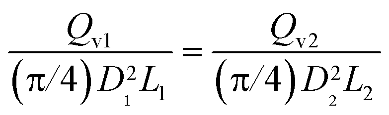 | (A-1) |
 | (A-2) |
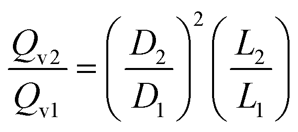
Accordingly, the scale-down of the fluid velocity is:
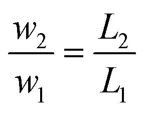 | (A-3) |
Typically, D1/D2 is over 100, while L1/L2 is below 10, and as a result, the fluid velocity could drop significantly in the lab reactor leading to low mass and heat transfer coefficients for the catalyst/fluid. To compensate this effect, reducing the pellet size is necessary. Let us consider the mass transfer. This can be described by a Froessling type equation, such as Sh = 2 + ReαpScβ, where the Sherwood number is Sh = kmdp/DA, the Reynolds particle number is Rep = wdp/ν, and the Schmidt number is Sc = ν/DA. The notations signify the following: km, the mass transfer coefficient (m/s); dp, the pellet equivalent diameter; DA, the external diffusion coefficient of species A; and ν, the fluid kinematic viscosity. It results into the following relation, which can be used for estimating the effect of the fluid velocity and the particle diameter on the rate of mass transfer:
| km = Cwαdα−1p ≅ C(w/dp)0.5 | (A-4) |
As a numerical example, we take the above industrial catalytic reactor. The production rate is 150000 tpy for 8000 hours of continuous operation. The LHSV is 0.7 h−1, while the methanol/oil feed ratio is 0.5. The yield of TAG to FAME is 90%. The industrial catalyst consists of pellets of 3 mm equivalent diameter. For the laboratory reactor, a tube of 6 mm ID is selected. The ratio of diameters is D1/D2 = 220/6 = 400. Assuming a fictive fluid velocity of 1 mm s−1, a tube length of 5.14 m would ensure the same LHSV as in the industrial reactor. The length ratio becomes L1/L2 = 16.5/5.14 = 3.2. The similarity of mass and heat conditions can be fulfilled if the pellet size is reduced to 0.94 mm. The combined oil and methanol flow for the laboratory reactor would be about 100 ml h−1.
Acknowledgements
This work is part of the Sustainable Chemistry Research Priority Area of the UvA, http://suschem.uva.nl.References
- Z. Strassberger, S. Tanase and G. Rothenberg, RSC Adv., 2014, 4, 25310–25318 RSC.
- R. Beerthuis, G. Rothenberg and N. R. Shiju, Green Chem., 2015, 17, 1341–1361 RSC.
- J. van Gerpen and G. Knothe, Basics of transesterification reaction, in The biodiesel handbook, 2005, AOCS Press Search PubMed.
- C. Perego and M. Ricci, Catal. Sci. Technol., 2012, 2, 1776–1786 CAS.
- REN21, Renewable 2015 Global status report, Available at http://www.ren21.net, Last accessed 5 April 2016 Search PubMed.
- European Biofuels Technology Platform (EBTP), Factsheets. Available at http://www.biofuelstp.eu. Last accessed 5 April 2015.
- A. Azapagic and H. Stichnote, Life cycle sustainability assessment of biofuels, in Handbook of biofuels production, Woodhead Publ., UK, 2011 Search PubMed.
- Wikipedia, Environmental impact of biodiesel. Available at https://en.wikipedia.org. Last accessed 4 April 2016.
- US EPA, Final renewable fuels standards for 2014 to, 2017, Available at https://www.epa.gov, Last accessed 5 April 2016 Search PubMed.
- A. F. Lee and K. Wilson, Catal. Today, 2014, 242, 3–18 CrossRef.
- L. Bournay, G. Hillion, P. Boucot, J. Chodorge, C. Bronner and A. Forestiere, U.S. Pat., 6878837, 2005 Search PubMed.
- L. Bourney, D. Casanave, B. Delfort, G. Hillion and J. A. Chodorge, Catal. Today, 2005, 106, 109–115 Search PubMed.
- M. Bloch, L. Bournay, D. Casanave, J. A. Chodorge, V. Coupard, G. Hillion and D. Lorne, Oil & Gas Science and Technology – Rev. IFP, 2008, 63, 405–417 CAS.
- A. A. Kiss, A. C. Dimian and G. Rothenberg, Adv. Synth. Catal., 2006, 348, 75–81 CrossRef CAS.
- A. A. Kiss, F. Omota, A. C. Dimian and G. Rothenberg, Top. Catal., 2006, 40, 141–150 CrossRef CAS.
- A. A. Kiss, A. C. Dimian and G. Rothenberg, Energy & Fuels, 2008, 22, 598–604 CrossRef CAS.
- A. C. Dimian and S. Bildea, Biodiesel Manufacturing, in Computer-Aided Design Case Studies, Wiley, 2008 Search PubMed.
- F. Omota, A. C. Dimian and A. Bliek, Chem. Eng. Sci., 2003, 58, 3175–3185 CrossRef CAS.
- A. C. Dimian, G. Rothenberg and R. Schut, Internal report Yellowdiesel B.V., The Netherlands, 2010 Search PubMed.
- A. C. Dimian, Integrated Design and Simulation of Chemical Processes, Elsevier, 2003, CACE-13 Search PubMed.
- A. West, D. Posarac and N. Ellis, Bioresour. Technol., 2008, 99, 6587–6601 CrossRef CAS PubMed.
- R. Stern, G. Hillion and J. J. Rouxel, US Pat., 5908946, 1999 Search PubMed.
- G. Hillion, S. Leporq, D. LePennec and B. Delfort, US Pat., 0234448, 2004; see also US Pat., 2005/0113588A1 Search PubMed.
- D. Bazer-Bachi, V. Coupard, S. Maury, V. Pugnet, I. Clemencon and A. A. Quoineaud, US pat., 0092730 A1 2011 Search PubMed.
- V. Pugnet, S. Maury, V. Coupard, A. Dandeu, A. Quoineaud, J. L. Bonneau and D. Tichit, Appl. Catal., 2010, 374, 71–78 CrossRef CAS.
- F. Allain, J. F. Portha, E. Girot, L. Falk, A. Dandeu and V. Coupard, Chem. Eng. J., 2016, 283, 6833–6845 CrossRef.
- M. Di Serio, R. Tesser, L. Pengmei and E. Santacesaria, Energy Fuels, 2008, 22, 207–217 CrossRef CAS.
- Y. C. Sharma, B. Singh and J. Korstad, Fuel, 2011, 90, 1309–1324 CrossRef CAS.
- A. F. Lee, J. A. Bennett, J. C. Manayil and K. Wilson, Chem. Soc. Rev., 2014, 43, 7887 RSC.
- D. G. Cantrell, L. J. Gillie, A. F. Lee and K. Wilson, Appl. Catal., A, 2005, 287, 183 CrossRef CAS.
- N. Barakos, S. Pasias and N. Papayannakos, Bioresour. Technol., 2008, 99, 5037–5042 CrossRef CAS PubMed.
- G. S. Macala, A. W. Robertson, C. L. Johnson, Z. B. Day, R. S. Lewis, M. White, A. V. Iretskii and P. C. Ford, Catal. Lett., 2008, 122, 205–209 CrossRef CAS.
- C. M. Silva, N. F. P. Ribeiro, M. Souza and D. Aranda, Fuel Process. Technol., 2010, 91, 205–210 CrossRef CAS.
- M. Di Serio, S. Mallardo, G. Carotenuto, R. Tesser and E. Santacesaria, Catal. Today, 2012, 54–58 CrossRef CAS.
- K. Wilson, C. Hardacre, A. F. Lee, J. Montero and L. Shellard, Green Chem., 2008, 10, 654–659 RSC.
- P. S. Sreeprasanth, R. Srivastava, D. Srinivas and P. Rattnassamy, Appl. Catal., A, 2006, 314, 148–159 CrossRef CAS.
- D. Srinivas and P. Rattnassamy, US Pat., 8124801, 2012 Search PubMed.
- A. C. Dimian, Z. Srokol, M. Mitelmeijer and G. Rothenberg, Top. Catal., 2010, 53, 1197–1201 CrossRef CAS.
- P. Kutálek, L. Čapek, L. Smoláková and D. Kubička, Fuel Process. Technol., 2014, 122, 176–181 CrossRef.
- N. Tapanes, D. A. G. Aranda, J. de Mosquito Carneiro and O. Ceva Antunes, Fuel, 2008, 87, 2286–2295 CrossRef.
- A. C. Dimian, G. Rothenberg and R. Schut, Euro Pat., EP 2457648 A1/WO 2012072574 A1, 2012 Search PubMed.
- V. Jordan and B. Gutsche, Chemosphere, 2001, 43, 99–105 CrossRef CAS PubMed.
- A. V. Gaikwad, V. Boffa, J. E. ten Elshof and G. Rothenberg, Angew. Chem., Int. Ed., 2008, 47, 5407–5410 CrossRef CAS PubMed.
- P. Cao, Y. André, M. A. Dubé, A. Y. Tremblay and M. Katie, Ind. Eng. Chem. Res., 2007, 46, 52–58 CrossRef CAS.
- M. C. Sérgi Gomes, N. C. Pereira and S. T. Davantel de Barros, J. Membr. Sci., 2010, 352, 271–276 CrossRef.
- P. Cao, M. A. Dubé and Y. T. André, Biomass Bioenergy, 2008, 32, 1028–1036 CrossRef CAS.
- P. Cao, M. A. Dubé and A. Y. Tremblay, Fuel, 2008, 87, 825–833 CrossRef CAS.
- M. A. Dubé, A. Y. Tremblay and J. Liu, Bioresour. Technol., 2007, 98, 639–647 CrossRef PubMed.
- A. A. Kiss, Process intensification technologies for biodiesel production, Springer Briefs in Applied Sciences and Technology, 2014 Search PubMed.
- I. M. Atadashi, M. K. Aroua and A. Abdul Aziz, Renewable Energy, 2011, 36, 437–443 CrossRef CAS.
- J. F. Portha, F. Allain, V. Coupard, A. Dandeu, E. Girot, E. Schaer and L. Falk, Chem. Eng. J., 2012, 207–208, 285–298 CrossRef CAS.
| This journal is © The Royal Society of Chemistry 2016 |