Continuous flow hydrogenation of nitroarenes, azides and alkenes using maghemite–Pd nanocomposites†
Anuj K.
Rathi
a,
Manoj B.
Gawande
*a,
Vaclav
Ranc
a,
Jiri
Pechousek
a,
Martin
Petr
a,
Klara
Cepe
a,
Rajender S.
Varma
b and
Radek
Zboril
*a
aRegional Centre of Advanced Technologies and Materials, Department of Physical Chemistry, Faculty of Science, Palacky University, Šlechtitelů 11, Olomouc, 783 71, Czech Republic. E-mail: manoj.gawande@upol.cz; radek.zboril@upol.cz
bSustainable Technology Division, National Risk Management Research Laboratory, US Environmental Protection Agency, 26 West Martin Luther King Drive, MS 443, Cincinnati, Ohio 45268, USA
First published on 7th September 2015
Abstract
Maghemite-supported ultra-fine Pd (1–3 nm) nanoparticles, prepared by a simple co-precipitation method, find application in the catalytic continuous flow hydrogenation of nitroarenes, azides, and alkenes wherein they play an important role in the reduction of various functional groups on the surface of maghemite with catalyst loading (~6 wt% Pd). The salient features of the protocol include expeditious formation of reduced products in high yields under near ambient conditions with recycling of the catalyst (up to 12 cycles) without any decrease in selectivity and yield.
Introduction
Aromatic amines and their derivatives are employed in various important organic intermediates for the production of dyes and polymers in the pharmaceutical industry, and are frequently obtained via the reduction of nitro compounds.1 The reduction of C–C double and triple bonds, and other functional groups utilizes various catalysts that include noble (Pt, Pd, Ru, and Rh)2 as well as non-noble metal (Co, Ni and Cu)3 catalysts under a variety of reaction conditions; each reported catalytic protocol has its own advantages and disadvantages. Keeping in mind the importance of amines and alkanes in commodity chemicals and pharmaceuticals, catalytic hydrogenation reactions have been investigated under a variety of energy input systems namely microwave irradiation, ultrasonication, and ball milling or using benign solvent-free and water-mediated protocols.4 However, despite these significant advancements, catalytic hydrogenation reactions can still benefit from sustainable improvements.Continuous flow reactions are receiving tremendous interest for applications in the development of selective processes because of their intrinsic advantages, when compared to conventional batch reactions; the ease of isolation or purification, reduction in waste emissions, safety, automation, and space-time-yield efficiency being prominent.5
The chemoselective and partial catalytic hydrogenation of functionalized hydrocarbons with multiple C![[double bond, length as m-dash]](https://www.rsc.org/images/entities/char_e001.gif) C and C
C and C![[triple bond, length as m-dash]](https://www.rsc.org/images/entities/char_e002.gif) C bonds is a very desirable process and prerequisite in the pharmaceutical and petrochemical industries.6 In general, the catalytic hydrogenation reaction (reduction of nitro compounds, C
C bonds is a very desirable process and prerequisite in the pharmaceutical and petrochemical industries.6 In general, the catalytic hydrogenation reaction (reduction of nitro compounds, C![[double bond, length as m-dash]](https://www.rsc.org/images/entities/char_e001.gif) C and C
C and C![[triple bond, length as m-dash]](https://www.rsc.org/images/entities/char_e002.gif) C bonds) often deploys various types of heterogeneous and noble metal-supported catalysts under continuous flow conditions.7 However, in most cases, catalysts cannot be reused and recycled or plagued by leaching of metals due to high pressure and related reaction parameters in the flow reactor.8 Consequently, it is prudent to design a stable, cost-effective, and reusable catalytic system for hydrogenation reactions.
C bonds) often deploys various types of heterogeneous and noble metal-supported catalysts under continuous flow conditions.7 However, in most cases, catalysts cannot be reused and recycled or plagued by leaching of metals due to high pressure and related reaction parameters in the flow reactor.8 Consequently, it is prudent to design a stable, cost-effective, and reusable catalytic system for hydrogenation reactions.
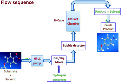
In recent years, there has been a remarkable rise in the exploitation of magnetic nanocomposites because of their preparation from inexpensive precursors, inert and stable nature and most importantly, their reusable and recyclable feature for several runs without impairment of catalytic activity and selectivity.9 It is not surprising, therefore, that there is an enormous demand for magnetically recyclable nanocatalysts in continuous flow processes.5c Herein, we describe hydrogenation reactions for the reduction of nitro, azide, and alkene functionalities under a continuous flow on recyclable maghemite decorated with Pd nanoparticles (Fig. 1).
Experimental
Materials and reagents
All commercial reagents were used as received unless otherwise mentioned. For analytical and preparative thin-layer chromatography (TLC), Merck, 0.2 mm and 0.5 mm Kieselgel GF 254 pre-coated were used, respectively. The spots were visualized with iodine and UV light. The reactions were performed on Thales Nano H-Cube continuous flow hydrogen reactors, utilising water electrolysis to generate hydrogen. The conversion and selectivity of the individual hydrogenation reactions were analyzed by GC employing chromatograph Agilent 6820 (Agilent, United States) equipped with a flame ionisation detector (FID) and chromatographic column DB5 (30 × 0.250 × 0.25). The following experimental parameters were applied: initial temperature 100 °C, increased to 250 °C at a rate of 10 °C min−1. The yield was determined using an internal standard.Synthesis of maghemite (γ-Fe2O3) nanoparticles
Magnetically separable maghemite was prepared by a chemical co-precipitation and dehydration method. Typically, FeSO4·7H2O (6.06 g, 21.79 mmol) and FeCl3·6H2O (11.75 g, 45.08 mmol) were dissolved in 100 mL of deionised water (previously degassed with nitrogen) under N2 atmosphere. The resulting mixture was stirred for 30 minutes and heated at 60 °C under vigorous stirring. When the temperature reached 60 °C, aqueous NH4OH (25 mL, 25–28% w/w) was added dropwise; the black precipitate was formed and heating continued for 2 hours under N2 atmosphere. The precipitate was magnetically separated and washed thoroughly with water until the supernatant liquor reached neutrality. The obtained material was dried in an oven at 100 °C for 12 hours.Preparation of maghemite–Pd nanocatalyst
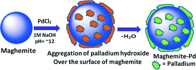
To a stirred mixture of palladium chloride (349 mg) and potassium chloride (1 g) in water (80 mL), maghemite (3 g) was added after 30 minutes. The resulting mixture was stirred at room temperature for 1 hour and the suspension was adjusted to pH 12–13 by slow addition of sodium hydroxide (1.0 M) in 45 minutes and stirring was further continued for 20 hours. The aqueous layer was decanted and the ensuing material was washed with distilled water (5 × 50 mL) and dried under vacuum at 60 °C for 12 hours to afford maghemite–Pd nanoparticles. The Pd content was found to be 3.92% as determined by ICP-MS.General procedure for the reduction of nitro compounds
The nitroarene/cyclic nitro compound (1 mmol) was dissolved in 5 mL of ethanol![[thin space (1/6-em)]](https://www.rsc.org/images/entities/char_2009.gif) :
:![[thin space (1/6-em)]](https://www.rsc.org/images/entities/char_2009.gif) ethyl acetate (1
ethyl acetate (1![[thin space (1/6-em)]](https://www.rsc.org/images/entities/char_2009.gif) :
:![[thin space (1/6-em)]](https://www.rsc.org/images/entities/char_2009.gif) 1) under sonication and the reaction mixture was passed through the 30 mm catalyst cartridge, (comprising 160 mg of maghemite–Pd (~6.2% Pd content) and 120 mg of crushed glass silica) at 30 °C under H2 pressure (gas flow rate 60 mL min−1) at a 500 uL min−1 flow rate. Progress of the reaction was monitored by TLC (thin layer chromatography). The volatiles were evaporated under reduced pressure and, in most cases, the obtained crude material was purified by column chromatography (silica 230–400/alumina; n-hexane
1) under sonication and the reaction mixture was passed through the 30 mm catalyst cartridge, (comprising 160 mg of maghemite–Pd (~6.2% Pd content) and 120 mg of crushed glass silica) at 30 °C under H2 pressure (gas flow rate 60 mL min−1) at a 500 uL min−1 flow rate. Progress of the reaction was monitored by TLC (thin layer chromatography). The volatiles were evaporated under reduced pressure and, in most cases, the obtained crude material was purified by column chromatography (silica 230–400/alumina; n-hexane![[thin space (1/6-em)]](https://www.rsc.org/images/entities/char_2009.gif) :
:![[thin space (1/6-em)]](https://www.rsc.org/images/entities/char_2009.gif) ethyl acetate/MeOH
ethyl acetate/MeOH![[thin space (1/6-em)]](https://www.rsc.org/images/entities/char_2009.gif) :
:![[thin space (1/6-em)]](https://www.rsc.org/images/entities/char_2009.gif) DCM mixture) and a highly polar compound was isolated by crystallization (Table 2, entries 5, 7 and 10).
DCM mixture) and a highly polar compound was isolated by crystallization (Table 2, entries 5, 7 and 10).
General procedure for the reduction of alkenes
Alkene (1 mmol) was dissolved in 5 mL ethanol under sonication and the reaction mixture was passed through the catalyst cartridge (same cartridge as described earlier) at 50 °C under H2 pressure (gas flow rate 60 mL min−1) at a 300 uL min−1 flow rate. The collected volatiles were evaporated under reduced pressure to obtain the corresponding products which are further analyzed by GC with the corresponding authentic sample to obtain the conversions and yields.Results and discussion
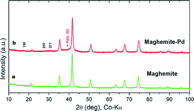
The maghemite–Pd nanocatalyst was prepared by the wet impregnation method followed by a dehydration process (Scheme 1).9g A transmission electron microscope (TEM) was employed to evaluate the size, distribution, and morphology of the synthesized maghemite–Pd nanocomposites. X-ray photoelectron spectroscopy (XPS) characterization was conducted to monitor the surface composition and valence states. Chemical analysis was carried out using the field-emission gun-scanning electron microscopy-electron dispersive spectrometry (FEG-SEM-EDS) and high-angle annular dark-field scanning transmission electron microscopy (HAADF-STEM) techniques to identify the various elements.The XRD patterns of the maghemite and maghemite–Pd nanocomposite are shown in Fig. 2. In both profiles, all the peaks correspond to the maghemite's (γ-Fe2O3) structure; the presence of reflections at (110), (210), and (211) supports the occurrence of maghemite with partially ordered vacancies (PDF card 01-089-5892). Furthermore, Rietveld analysis was performed on both XRD patterns to calculate the lattice parameter of maghemite (a = 8.355 Å) and the average crystalline domain size is calculated using the broadening of the most intense peaks, implying the crystallite sizes of the samples in nanometer dimensions (~15 nm). Palladium-related diffraction peaks are barely extractable from the XRD pattern of maghemite–Pd nanocomposite which can be attributed either to its low percentage or the much reduced size of the Pd particles (<3 nm).10
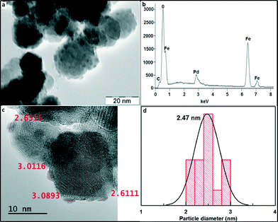
Fig. 3 shows the TEM image of the maghemite–Pd catalyst with a nearly spherical geometry of the maghemite support having a size in the range of 10–30 nm, thus corroborating the average size determination of maghemite from XRD. The maghemite nanoparticles are homogeneously covered by Pd nanoparticles – the fact explaining the absence of Pd peaks in the XRD pattern of maghemite–Pd nanocomposite. The measurement of the size of Pd NPs by HRTEM clearly indicates the presence of ultra-small Pd nanoparticles (1–3 nm) (Fig. 3c and d). Furthermore, the morphology of maghemite–Pd after 12 consecutive cycles was verified by TEM; no major visible changes in the morphology were observed (Fig. S1b, ESI†).
To explore the chemical nature of palladium in the maghemite–Pd sample, XPS analysis was performed for the freshly prepared maghemite–Pd and the reused catalyst after 12 reactions cycles (Fig. 4); the XPS spectra of both samples exhibit dominantly Pd(0) and PdO species without any significant change after recycling (Fig. 4). The most intense peaks of doublet in the maghemite–Pd sample at 335.50 eV and 340.76 eV are assignable to metallic Pd(0) and the second weaker set of peaks at 336.81 eV and 342.07 eV could be assigned to Pd(II) in an oxidized form such as PdO.11 Thus, the TEM data clearly manifest that the maghemite–Pd nanocatalyst is composed of globular maghemite (10–30 nm) nanoparticles. The palladium particles are predominantly in the form of metallic Pd with a minor presence of PdO.
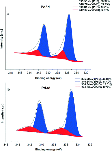 | ||
| Fig. 4 XPS spectrum of (a) maghemite–Pd nanocatalyst and (b) recycled maghemite–Pd after 12 reactions; positions of the metallic Pd(0) and PdO are denoted in blue and red, respectively. | ||
To distinguish chemical components of the nanocomposite and the chemical nature of the magnetic support (maghemite vs. magnetite), HAADF-STEM and Mössbauer spectroscopy were conducted. High-angle annular dark-field scanning transmission electron microscopy (Fig. 5) confirmed that Pd nanoparticles (green) functionalize the iron oxide surface very homogeneously.
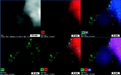 | ||
| Fig. 5 High-angle annular dark-field scanning transmission electron microscopy (HAADF-STEM) images showing elemental mapping of Pd, Fe, and O atoms. | ||
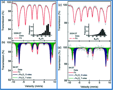
57Fe Mössbauer spectroscopy on maghemite–Pd was carried out to clarify the oxidation state of Fe ions in the synthesized and recycled samples as the XRD data cannot distinguish between maghemite and magnetite. The recorded room temperature/zero-field (300 K/0 T) and low temperature in-field Mössbauer spectra (5 K/5 T) are shown in Fig. 6 and the values of the Mössbauer hyperfine parameters, derived from the spectra fitting, are listed in Table S1, ESI.†
The room temperature Mössbauer spectra of the synthesized maghemite–Pd and the recovered maghemite–Pd samples show one asymmetrical sextet component (Fig. 6a and c). The profiles of the spectra are typical of the γ-Fe2O3 phase with iron cations solely in the Fe3+ oxidation state.12 The Mössbauer spectra were recorded at a low temperature (5 K) to facilitate the resolution of the Mössbauer resonant lines via application of an external magnetic field of 5 T. The Mössbauer spectra of both samples are well fitted with two sextets (Fig. 6b and d). The first sextet with a lower isomer shift (δ) and higher hyperfine magnetic field (Beff) corresponds to the Fe3+ ions in the tetrahedral sites (T-sites) of the spinel γ-Fe2O3 crystal structure while the second sextet with a higher δ and lower Beff is ascribable to the Fe3+ ions occupying the octahedral sites (O-sites) in the γ-Fe2O3 crystal structure.
For the synthesized sample, the spectral ratio between the T-sextet to O-sextet is very close to 0.6 (Fig. 6b) indicating a stoichiometric nature of maghemite with vacancies present only in the O-sites. However, after the reaction, for the recovered sample (Fig. 6d), the spectral ratio of T![[thin space (1/6-em)]](https://www.rsc.org/images/entities/char_2009.gif) :
:![[thin space (1/6-em)]](https://www.rsc.org/images/entities/char_2009.gif) O is below 0.5, which reflects a partially non-stoichiometric character of the maghemite particles, probably due to the occurrence of vacancies at the T sites. In summary, the in-field Mössbauer data confirm well the stoichiometric maghemite structure with no indications of Fe(II) ions. Similarly, after the sample recycling, there is no remarkable change in the structure/valence state of the magnetic support. This fact reflects, together with the previously discussed XPS data, the stability of maghemite–Pd nanocatalyst keeping its chemical nature/crystal structure after recycling. As per analysis, we observed that the hyperfine parameters slightly changed, which might be due to the small changes in the iron surroundings or palladium in the sample after the reaction.
O is below 0.5, which reflects a partially non-stoichiometric character of the maghemite particles, probably due to the occurrence of vacancies at the T sites. In summary, the in-field Mössbauer data confirm well the stoichiometric maghemite structure with no indications of Fe(II) ions. Similarly, after the sample recycling, there is no remarkable change in the structure/valence state of the magnetic support. This fact reflects, together with the previously discussed XPS data, the stability of maghemite–Pd nanocatalyst keeping its chemical nature/crystal structure after recycling. As per analysis, we observed that the hyperfine parameters slightly changed, which might be due to the small changes in the iron surroundings or palladium in the sample after the reaction.
The applicability of the maghemite–Pd nanocatalyst was evaluated in the reduction of nitroarenes using 4-methoxy nitrobenzene as the model substrate in ethanol at 30 °C (Table 1). First, the control reaction was conducted with only maghemite; in the absence of palladium, no product formation was observed (Table 1, entry 1).
| Entry | Catalyst | Temp. | Conversionb (%) | Isolated yield (%) |
|---|---|---|---|---|
| a Reaction conditions: 4-methoxy nitrobenzene (1 mmol), maghemite–Pd (wt%), EtOH (5 mL), flow rate (500 uL min−1), H2 (gas flow rate 60 mL min−1). b Conversion calculated on the basis of GC analysis. c H2 (30 mL per minute). tr = 0.75 min. | ||||
| 1 | Maghemite | 70°C | — | — |
| 2 | Maghemite–Pd (9%) | 70°C | >99 | 94 |
| 3 | Maghemite–Pd (7%) | 70°C | >99 | 95 |
| 4 | Maghemite–Pd (7%) | 30°C | >99 | 93 |
| 5 | Maghemite–Pd (6.2%) | 30°C | >99 | 94 |
| 6 | Maghemite–Pd (6.2%) | 30°C | >81 | 72c |
| 7 | Maghemite–Pd (3.9%) | 30°C | >65 | 53 |
The optimized reaction conditions were identified by conducting a series of experiments with different Pd loadings and variation of temperature. The results revealed that full conversion could be achieved with ~6.2 wt% of Pd loadings using hydrogen in a full mode (full H2 mode which corresponds to a gas flow rate of 60 mL min−1) at a 500 uL min−1 flow rate (Table 1, entries 2–5), while 30 mL min−1 hydrogen pressure showed 81% conversion (Table 1, entry 6). It was noticed that the low loading of catalyst (3.92%) showed only 65% conversion (Table 1, entry 7). These optimized reaction conditions were then applied to the reduction of a variety of substrates bearing additional and reducible functional groups (–CONH2, –SMe, –CN, –OH, –SO2NH2, –COOH etc.) attached to the aromatic ring (Table 2).
| Entry | Substrate | Product | Yieldb (%) |
|---|---|---|---|
a Reaction conditions: nitro compound (1 mmol), maghemite–Pd (6.2 wt%), EtOH![[thin space (1/6-em)]](https://www.rsc.org/images/entities/char_2009.gif) : :![[thin space (1/6-em)]](https://www.rsc.org/images/entities/char_2009.gif) EtOAc (5 mL, 1 EtOAc (5 mL, 1![[thin space (1/6-em)]](https://www.rsc.org/images/entities/char_2009.gif) : :![[thin space (1/6-em)]](https://www.rsc.org/images/entities/char_2009.gif) 1), temp 30 °C, flow rate (500 uL min−1), H2 (gas flow rate 60 mL min−1), tr = 0.75 min.
b Isolated yield.
c Isolated by crystallization.
d Isolated as hydrochloride salt.
e
N-Benzyl-4-nitroaniline (0.5 mmol), maghemite–Pd (6.2 wt%), EtOAc 1), temp 30 °C, flow rate (500 uL min−1), H2 (gas flow rate 60 mL min−1), tr = 0.75 min.
b Isolated yield.
c Isolated by crystallization.
d Isolated as hydrochloride salt.
e
N-Benzyl-4-nitroaniline (0.5 mmol), maghemite–Pd (6.2 wt%), EtOAc![[thin space (1/6-em)]](https://www.rsc.org/images/entities/char_2009.gif) : :![[thin space (1/6-em)]](https://www.rsc.org/images/entities/char_2009.gif) EtOH (12 mL, 5 EtOH (12 mL, 5![[thin space (1/6-em)]](https://www.rsc.org/images/entities/char_2009.gif) : :![[thin space (1/6-em)]](https://www.rsc.org/images/entities/char_2009.gif) 1), temp 70 °C, 300 uL min−1, tr = 1.25 min. 1), temp 70 °C, 300 uL min−1, tr = 1.25 min.
|
|||
| 1 |

|

|
94 |
| 2 |

|

|
94 |
| 3 |

|

|
94 |
| 4 |

|

|
92 |
| 5 |

|

|
98c |
| 6 |

|

|
93d |
| 7 |

|

|
95c |
| 8 |

|

|
95 |
| 9 |

|

|
87 |
| 10 |

|

|
88c |
| 11 |

|

|
93 |
| 12 |

|

|
95 |
| 13 |

|

|
86e |
In all cases, excellent yields of amine (86–98%) were obtained by just passing the solution of nitroarenes in ethanol![[thin space (1/6-em)]](https://www.rsc.org/images/entities/char_2009.gif) :
:![[thin space (1/6-em)]](https://www.rsc.org/images/entities/char_2009.gif) ethyl acetate (1
ethyl acetate (1![[thin space (1/6-em)]](https://www.rsc.org/images/entities/char_2009.gif) :
:![[thin space (1/6-em)]](https://www.rsc.org/images/entities/char_2009.gif) 1) through the catalyst cartridge (Table 2, entries 1–10 and 13), the only exceptions being 4-nitrobenzonitrile and 4-nitrobenzoic acid which afforded 87% and 88% isolated yields, respectively (Table 2, entries 9, 10). The use of ethyl acetate was found beneficial as it helps improve the solubility of nitroarenes. Among the acyclic compounds, nitrocyclopentane gave a high yield (93%) of cyclopentyl amine, with no detectable side products, although mechanistically, the formation of amine proceeds via the intermediacy of nitroso derivatives and hydroxylamine species;13 the formation of hydroxylamines during the catalytic hydrogenation is often implicated in the ensuing explosions.13 The azido functionality is often deployed in organic synthesis and usually serves as a latent amino group which can be converted into an amine via reduction. The optimized conditions were utilized for the reduction of 1-azido-4-methoxy benzene and 1-azido-4-methyl benzene, which afforded excellent yields of products of 93% and 95%, respectively (Table 2, entries 11 and 12). Similarly, the reduction of N-benzyl-4-nitroaniline gave debenzylated benzene-1-4-diamine in 86% yield (Table 2, entry 13).
1) through the catalyst cartridge (Table 2, entries 1–10 and 13), the only exceptions being 4-nitrobenzonitrile and 4-nitrobenzoic acid which afforded 87% and 88% isolated yields, respectively (Table 2, entries 9, 10). The use of ethyl acetate was found beneficial as it helps improve the solubility of nitroarenes. Among the acyclic compounds, nitrocyclopentane gave a high yield (93%) of cyclopentyl amine, with no detectable side products, although mechanistically, the formation of amine proceeds via the intermediacy of nitroso derivatives and hydroxylamine species;13 the formation of hydroxylamines during the catalytic hydrogenation is often implicated in the ensuing explosions.13 The azido functionality is often deployed in organic synthesis and usually serves as a latent amino group which can be converted into an amine via reduction. The optimized conditions were utilized for the reduction of 1-azido-4-methoxy benzene and 1-azido-4-methyl benzene, which afforded excellent yields of products of 93% and 95%, respectively (Table 2, entries 11 and 12). Similarly, the reduction of N-benzyl-4-nitroaniline gave debenzylated benzene-1-4-diamine in 86% yield (Table 2, entry 13).
The viability of the catalytic system was further explored for the reduction of several of substituted alkenes using a H2 gas flow rate of 60 mL min−1 (full mode) at 50 °C (Table 3). In this case, ethyl benzene, 3-amino ethyl benzene, 4-methoxy ethyl benzene and 1,2-diphenyl ethane were obtained in a nearly quantitative conversion, 4-fluro ethyl benzene and cyclooctene were obtained in >98% and >91% conversion, respectively. It was observed that when the flow rate is increased from 300 to 500 uL min−1, the reaction was incomplete and some unreacted starting material remained. Additionally, methyl cinnamate and methyl 3-(4-methoxyphenyl)acrylate underwent efficient hydrogenation with a flow rate of 300 uL min−1 at 70 °C (Table 3, entries 7 and 8).
| Entry | Substrate | Product | Conversionb (%) | Yieldc (%) |
|---|---|---|---|---|
| a Reaction conditions: substrate (1 mmol), maghemite–Pd (6.2 wt%), EtOH (5 mL), temp. 50 °C, flow rate 300 uL min−1, H2 (gas flow rate 60 mL min−1), tr = 0.75 min. b Conversions calculated on the basis of GC analysis. c Isolated yield. d Yields are determined by GC against internal integration. e Temp. 70 °C, isolated yields. | ||||
| 1 |

|

|
>99 | 95d |
| 2 |

|

|
>98 | 93d |
| 3 |

|

|
>99 | 96d |
| 4 |

|

|
>91 | 86d |
| 5 |

|

|
>99 | 94d |
| 6 |

|

|
>99 | 93d |
| 7 |

|

|
>99 | 94e |
| 8 |

|

|
>99 | 95e |
The salient beneficial feature of the reduction under flow conditions has been the recyclability of the catalyst. It is important to note that this magnetic support (maghemite) plays a crucial role in the successful reusability of the catalysts. Due to the presence of a hydroxyl group on the surface of the maghemite support, there is a sturdy interaction between maghemite and Pd NPs, which certainly results in the minimal leaching of Pd. The developed catalyst was reused and recycled for 12 times successfully with excellent conversion and yield without any reactivation, which are important performance metrics for cost-effective industrial processes (see Table S2, ESI†). The ICP-MS analysis indicates 0.000126, 0.000121, and 0.000113 Pd% leaching after the first, third and seventh reaction cycles.
The hydrogenation reactions, catalyzed by maghemite–Pd nanocomposites, in a continuous flow mode have several advantages relative to batch processes, where unique solid–gas–liquid triphasic reaction conditions prevail during the hydrogenation reactions.14 Most of the reported traditional catalysts are deployed under homogeneous conditions and are not reusable, making the protocol expensive.15 Also, the present catalytic protocol is comparable with reported methods used in continuous flow methods (Tables S3 and S4, ESI†). In contrast, maghemite–Pd nanocomposites could be easily retrieved and reused for several reaction cycles with barely observable leaching of Pd metal, which renders this catalytic protocol truly sustainable. Additionally, no hydrogen balloon/gas cylinder is used for the reactions, as in situ generated hydrogen gas from water certainly increases the safety aspects.16 We believe that several other hydrogenation reactions could be performed using this catalyst.
Conclusions
In summary, we have developed continuous flow hydrogenation protocols for the reduction of nitroarenes, azides, and alkenes catalyzed by ultra-fine (1–3 nm) Pd nanoparticles supported on a recyclable maghemite support. The corresponding products were obtained in good to excellent yields under continuous flow and without any requirements for filtration. The stability of the nanocatalyst was found to be impeccable with the added advantage that it could be used successively for 12 times without a major loss of its activity. The structure and morphology of the reused catalyst was confirmed by X-ray photoelectron spectroscopy and transmission electron microscopy analysis. Notably, a very negligible leaching of Pd metal was observed and the Pd species remained intact throughout the reaction cycles. The catalyst described in this work provides clear advantages in terms of environmental impact due to lower metal loading, and no requirements of other additives, which bode well for its adoption in industrial processes. The results obtained are of importance to the improvement of sustainable protocols for fine chemicals and, particularly for large-scale reactions.Acknowledgements
The authors thank Jana Straska for TEM and Martin Kuba for ICP-MS analysis. The authors acknowledge the support from the Ministry of Education, Youth and Sports of the Czech Republic (LO1305) and by the Operational Program Education for Competitiveness – European Social Fund (project CZ.1.07/2.3.00/30.0041 and CZ.1.07/2.4.00/31.0189) of the Ministry of Education, Youth and Sports of the Czech Republic. The work is also funded from the Palacky University Institutional support and IGA grant (Project no. IGA-PrF-2015-017).References
- M. Baghbanzadeh, T. N. Glasnov and C. O. Kappe, J. Flow Chem., 2013, 3, 109–113 CrossRef.
- (a) Y. Jang, S. Kim, S. W. Jun, B. H. Kim, S. Hwang, I. K. Song, B. M. Kim and T. Hyeon, Chem. Commun., 2011, 47, 3601–3603 RSC; (b) V. Pandarus, R. Ciriminna, F. Béland and M. Pagliaro, Adv. Synth. Catal., 2011, 353, 1306–1316 CrossRef CAS PubMed; (c) J. Li, X.-Y. Shi, Y.-Y. Bi, J.-F. Wei and Z.-G. Chen, ACS Catal., 2011, 1, 657–664 CrossRef CAS; (d) F.-X. Felpin and E. Fouquet, Chem. – Eur. J., 2010, 16, 12440–12445 CrossRef CAS PubMed.
- (a) G. Liang, H. Cheng, W. Li, L. He, Y. Yu and F. Zhao, Green Chem., 2012, 14, 2146–2149 RSC; (b) U. Sharma, P. Kumar, N. Kumar, V. Kumar and B. Singh, Adv. Synth. Catal., 2010, 352, 1834–1840 CrossRef CAS PubMed; (c) M. B. Gawande, H. Guo, A. K. Rathi, P. S. Branco, Y. Chen, R. S. Varma and D.-L. Peng, RSC Adv., 2013, 3, 1050–1054 RSC; (d) M. B. Gawande, A. K. Rathi, P. S. Branco, I. D. Nogueira, A. Velhinho, J. J. Shrikhande, U. U. Indulkar, R. V. Jayaram, C. A. A. Ghumman, N. Bundaleski and O. M. N. D. Teodoro, Chem. – Eur. J., 2012, 18, 12628–12632 CrossRef CAS PubMed.
- (a) T. Marimuthu and H. B. Friedrich, ChemCatChem, 2012, 4, 2090–2095 CrossRef CAS PubMed; (b) Y. Monguchi, Y. Fujita, S. Hashimoto, M. Ina, T. Takahashi, R. Ito, K. Nozaki, T. Maegawa and H. Sajiki, Tetrahedron, 2011, 67, 8628–8634 CrossRef CAS PubMed; (c) O. Verho, A. Nagendiran, E. V. Johnston, C.-W. Tai and J.-E. Baeckvall, ChemCatChem, 2013, 5, 612–618 CrossRef CAS PubMed; (d) Z. Sun, H. Zhang, G. An, G. Yang and Z. Liu, J. Mater. Chem., 2010, 20, 1947–1952 RSC; (e) M. K. Basu, F. F. Becker and B. K. Banik, Tetrahedron Lett., 2000, 41, 5603–5606 CrossRef CAS; (f) A. Stolle, T. Szuppa, S. E. S. Leonhardt and B. Ondruschka, Chem. Soc. Rev., 2011, 40, 2317–2329 RSC; (g) C.-H. Pelisson, A. Denicourt-Nowicki, C. Meriadec, J.-M. Greneche and A. Roucoux, ChemCatChem, 2015, 7, 309–315 CrossRef CAS PubMed.
- (a) F. Mastronardi, B. Gutmann and C. O. Kappe, Org. Lett., 2013, 15, 5590–5593 CrossRef CAS PubMed; (b) M. Damm, B. Gutmann and C. O. Kappe, ChemSusChem, 2013, 6, 978–982 CrossRef CAS PubMed; (c) D. Obermayer, A. M. Balu, A. A. Romero, W. Goessler, R. Luque and C. O. Kappe, Green Chem., 2013, 15, 1530–1537 RSC; (d) K. R. Knudsen, J. Holden, S. V. Ley and M. Ladlow, Adv. Synth. Catal., 2007, 349, 535–538 CrossRef CAS PubMed; (e) M. M. Moghaddam, B. Pieber, T. Glasnov and C. O. Kappe, ChemSusChem, 2014, 7, 3122–3131 CrossRef CAS PubMed; (f) T. Ouchi, C. Battilocchio, J. M. Hawkins and S. V. Ley, Org. Process Res. Dev., 2014, 18, 1560–1566 CrossRef CAS; (g) M. V. Rojo, L. Guetzoyan and I. R. Baxendale, Org. Biomol. Chem., 2015, 13, 1768–1777 RSC; (h) E. Alza, C. Rodriguez-Escrich, S. Sayalero, A. Bastero and M. A. Pericas, Chem. – Eur. J., 2009, 15, 10167–10172 CrossRef CAS PubMed; (i) C. Ayats, A. H. Henseler, E. Dibello and M. A. Pericas, ACS Catal., 2014, 4, 3027–3033 CrossRef CAS; (j) S. L. Bourne, P. Koos, M. O'Brien, B. Martin, B. Schenkel, I. R. Baxendale and S. V. Ley, Synlett, 2011, 2643–2647 CAS; (k) J. Izquierdo, C. Ayats, A. H. Henseler and M. A. Pericas, Org. Biomol. Chem., 2015, 13, 4204–4209 RSC; (l) C. B. Kelly, C. Lee and N. E. Leadbeater, Tetrahedron Lett., 2011, 52, 263–265 CrossRef CAS PubMed; (m) R. Martin-Rapun, S. Sayalero and M. A. Pericas, Green Chem., 2013, 15, 3295–3301 RSC.
- (a) A. Kawanishi, C. Miyamoto, Y. Yabe, M. Inai, T. Asakawa, Y. Hamashima, H. Sajiki and T. Kan, Organic Letters, 2013, 15, 1306–1309 CrossRef CAS PubMed; (b) M. Cano, A. M. Benito, W. K. Maser and E. P. Urriolabeitia, New J. Chem., 2013, 37, 1968–1972 RSC.
- (a) J. D. Lewis, S. Van de Vyver, A. J. Crisci, W. R. Gunther, V. K. Michaelis, R. G. Griffin and Y. Román-Leshkov, ChemSusChem, 2014, 7, 2255–2265 CrossRef CAS PubMed; (b) P. N. Liu, P. M. Gu, F. Wang and Y. Q. Tu, Org. Lett., 2004, 6, 169–172 CrossRef CAS PubMed; (c) M. Irfan, T. N. Glasnov and C. O. Kappe, ChemSusChem, 2011, 4, 300–316 CrossRef CAS PubMed.
- D. Cantillo and C. O. Kappe, ChemCatChem, 2014, 6, 3286–3305 CAS.
- (a) M. B. Gawande, P. S. Branco and R. S. Varma, Chem. Soc. Rev., 2013, 42, 3371–3393 RSC; (b) M. B. Gawande, R. Luque and R. Zboril, ChemCatChem, 2014, 6, 3312–3313 CAS; (c) M. B. Gawande, A. K. Rathi, J. Tucek, K. Safarova, N. Bundaleski, O. M. N. D. Teodoro, L. Kvitek, R. S. Varma and R. Zboril, Green Chem., 2014, 16, 4137–4143 RSC; (d) D. Wang and D. Astruc, Chem. Rev., 2014, 114, 6949–6985 CrossRef CAS PubMed; (e) R. B. Nasir Baig and R. S. Varma, Green Chem., 2013, 15, 398–417 RSC; (f) M. B. Gawande, Y. Monga, R. Zboril and R. K. Sharma, Coord. Chem. Rev., 2015, 288, 118–143 CrossRef CAS PubMed; (g) S. N. Shelke, S. R. Bankar, G. R. Mhaske, S. S. Kadam, D. K. Murade, S. B. Bhorkade, A. K. Rathi, N. Bundaleski, O. M. N. D. Teodoro, R. Zboril, R. S. Varma and M. B. Gawande, ACS Sustainable Chem. Eng., 2014, 2, 1699–1706 CrossRef CAS.
- S. Akbayrak, M. Kaya, M. Volkan and S. Özkar, Appl. Catal., B, 2014, 147, 387–393 CrossRef CAS PubMed.
- M. Liao, Q. Hu, J. Zheng, Y. Li, H. Zhou, C.-J. Zhong and B. H. Chen, Electrochim. Acta, 2013, 111, 504–509 CrossRef CAS PubMed.
- (a) R. Zboril, M. Mashlan and D. Petridis, Chem. Mater., 2002, 14, 969–982 CrossRef CAS; (b) J. Tucek, R. Zboril and D. Petridis, J. Nanosci. Nanotechnol., 2006, 6, 926–947 CrossRef CAS PubMed.
- D. Cantillo, M. M. Moghaddam and C. O. Kappe, J. Org. Chem., 2013, 78, 4530–4542 CrossRef CAS PubMed.
- M. Irfan, T. N. Glasnov and C. O. Kappe, ChemSusChem, 2011, 4, 300–316 CrossRef CAS PubMed.
- M. A. Mercadante, C. B. Kelly, C. Lee and N. E. Leadbeater, Org. Process Res. Dev., 2012, 16, 1064–1068 CrossRef CAS.
- R. V. Jones, L. Godorhazy, N. Varga, D. Szalay, L. Urge and F. Darvas, J. Comb. Chem., 2006, 8, 110–116 CrossRef CAS PubMed.
Footnote |
| † Electronic supplementary information (ESI) available: Materials and reagents used, description of characterization techniques employed, TEM images of fresh catalyst and reused catalyst, values of the Mössbauer hyperfine parameters derived from the spectra fitting, and conversion values after reusability. See DOI: 10.1039/c5cy00956a |
| This journal is © The Royal Society of Chemistry 2016 |

