
Harvest and utilization of chemical energy in wastes by microbial fuel cells
Min
Sun
ab,
Lin-Feng
Zhai
a,
Wen-Wei
Li
b and
Han-Qing
Yu
*b
aDepartment of Chemical Engineering, Hefei University of Technology, Hefei, 230009, China
bCAS Key Laboratory of Urban Pollutant Conversion, Department of Chemistry, University of Science & Technology of China, Hefei, 230026, China. E-mail: hqyu@ustc.edu.cn; Fax: +86-551-63601592
First published on 3rd March 2016
Abstract
Organic wastes are now increasingly viewed as a resource of energy that can be harvested by suitable biotechnologies. One promising technology is microbial fuel cells (MFC), which can generate electricity from the degradation of organic pollutants. While the environmental benefits of MFC in waste treatment have been recognized, their potential as an energy producer is not fully understood. Although progresses in material and engineering have greatly improved the power output from MFC, how to efficiently utilize the MFC's energy in real-world scenario remains a challenge. In this review, fundamental understandings on the energy-generating capacity of MFC from real waste treatment are provided and the challenges and opportunities are discussed. The limiting factors restricting the energy output and impairing the long-term reliability of MFC are also analyzed. Several energy storage and in situ utilization strategies for the management of MFC's energy are proposed, and future research needs for real-world application of this approach are explored.
 Min Sun | Min Sun received her PhD from the University of Science & Technology of China (USTC) under the supervision of Professor Han-Qing Yu in 2009. Her research has focused on mechanism elucidation and function exploration of microbial fuel cells (MFC). Dr Sun is currently an associate professor in the Department of Chemical Engineering, Hefei University of Technology (HFUT), China. She has published over 30 papers in peer-reviewed international journals. |
 Lin-Feng Zhai | Lin-Feng Zhai received his PhD from Hefei University of Technology, China, in 2007. He now works in the Department of Chemical Engineering at Hefei University of Technology (HFUT) as an associate professor. His research expertise is on renewable energy and environmental electrochemistry. He has published more than 20 papers in peer-reviewed international journals. |
 Wen-Wei Li | Wen-Wei Li is an associate professor from the Department of Chemistry, the University of Science & Technology of China (USTC). He received his PhD from the Chinese Academy of Sciences in 2008. After a postdoctoral training at USTC, he joined the faculty at this university in 2010. His research expertise is renewable energy, bioelectrochemistry and environmental biotechnology. He has published more than 60 peer-reviewed international papers and 5 invited book chapters. |
 Han-Qing Yu | Han-Qing Yu is currently a professor in the Department of Chemistry, USTC. He received his PhD from Tongji University, China in 1994. After that, he worked as a Marie Curie postdoctoral fellow at the University of Newcastle upon Tyne, a research fellow at the Nanyang Technological University, and a research assistant professor at the Hong Kong University. He is now an Associate Editor of Water Research and an editorial board member of eight international journals. His research interests include contaminant biodegradation and nanomaterials for environmental application. He has published more than 400 international peer-reviewed papers and 4 invited book chapters. |
1. Introduction
Renewable energy sources as sustainable and carbon-neutral alternatives to fossil fuels are highly desirable to alleviate the global energy crisis and environmental deterioration. According to the prediction of the European Renewable Energy Council, approximately half of the global energy supply will come from renewable energy by 2040.1 Various wastes are potentially a huge renewable energy reservoir due to their abundant availability and rich organic matter contents. Within the last decades, waste management has changed from being a sector primarily focusing on treatment and final disposal to a potential factory of energy and resources.2Bioelectrochemical systems (BESs) are receiving tremendous attention for the energy-efficient treatment of wastes. Microbial fuel cell (MFC) is one typical form of BES that directly converts chemical energy in wastes into electric energy by taking advantage of the synergy between microbial metabolism and a solid electron acceptor. In an MFC, microorganisms oxidize biodegradable organics at the anode, releasing electrons and protons. The bacteria that can extracellularly transfer electrons from organics to the anode electrode are called exoelectrogens.3 Electrons flow via an external circuit to the cathode and react with protons migrating inside the cell and electron acceptor molecules (Fig. 1). Many oxidants including oxygen (O2),4 ferricyanide,4,5 permanganate,6 dichromate7 and persulfate8 can be used as electron acceptors. Especially, O2 is the most commonly used due to its abundance and easy availability in air, low cost and non-toxicity.9
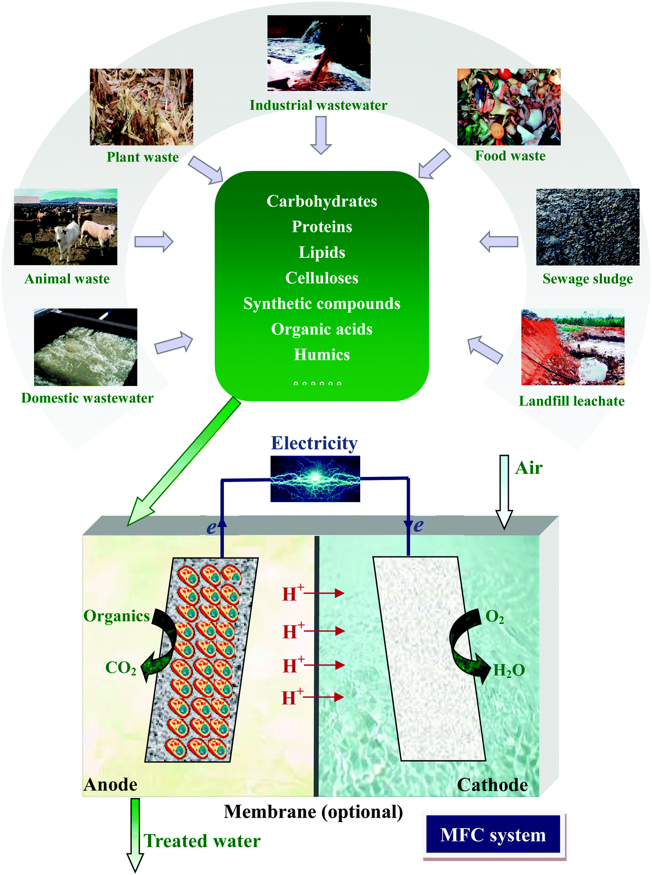 | ||
| Fig. 1 Electricity generation from wastes by MFC. | ||
MFC could be utilized as a potential alternative to conventional anaerobic digestion. In anaerobic digestion, energy is recovered in the form of methane (CH4) and/or hydrogen (H2), but more than 65% energy loss occurs in the process of biogas combustion and conversion into electricity.10 Moreover, the large quantity of undesirable impurities, such as hydrogen sulfide, in biogas should be removed in order to maintain an efficient operation of electric generator. In comparison, MFC allows a direct transformation of chemical energy (organic matters in waste) into electricity, theoretically affording less energy loss than the multi-step energy transformation needed by anaerobic digestion. MFC does not require gas treatment because the off-gas is mainly composed of carbon dioxide (CO2) with no useful energy content. Notably, biogenic CO2 generated from MFC is considered as environmentally neutral and of negligible contribution to global warming.11 This is a potential advantage over anaerobic digestion, whose off-gas CH4 contributes to major greenhouse gas emission from biological waste treatment.12 In addition, considerable environmental benefits can be achieved by the displacement of fossil-fuel based electricity with bioelectricity.13
MFC is operated in a way similar to a chemical fuel cell, except that it uses microorganisms as a catalyst at the anode. This endows it extra advantages. Unlike chemical fuel cells that utilize only limited types of chemicals as their fuel, MFC is able to produce electricity from an enormous range of low-grade wastes. In addition, chemical fuel cells are usually operated at high temperatures (500–1000 °C) and strong acidic or alkaline pH, posing rigid requirements on the reactor materials and adding operational costs.14 Yet the mild operational conditions with ambient temperature and neutral pH make MFC more reliable and safer.
MFC is a promising technology to combat the existing energy demand and pollution problem. While the environmental benefits of MFC have been recognized to suit a sustainable pattern of waste treatment, its potential as an energy producer has not been well addressed yet. Even though advances in material and engineering have greatly improved the power output from MFC, most of the achievements are obtained with synthetic cultures and pure substrates, rather than real wastes, i.e., complex mixtures of organic matters.15,16 For MFCs used to treat real wastes the primary goal is usually not to achieve a high power output, but to improve organic removal. As a result, the potential of MFC to recover electric energy from real wastes remains not clearly recognized. The successful demonstration of energy self-sufficient MFC necessitates the full exploitation of MFC's energy to harness real waste treatment.17 Traditionally, MFC is operated with an external resistor, and the maximum power obtained at its optimum external resistance is used to represent its energy-generating capacity. However, in order to harvest actual energy from MFC, the resistor has to be replaced with devices that can capture and store energy. Thus, the maximum power output of MFC can hardly be achieved because of the suboptimal external resistance in practical operation. While tremendous efforts have been devoted to boost the energy-generating capacity of MFC, how to effectively harvest and utilize the energy should be given more attention.
In this review, advances of MFC in the production of electric power from real wastes and the management of MFC energy for practical applications are overviewed. With a critical analysis of the opportunities and challenges of MFC towards the energy harvesting from real wastes, this review aims to identity the possible approaches for the virtual utilization of MFC energy, analyze the factors constraining the energy output of MFC, and prospects for energy storage and in situ utilization strategies to bring the MFC technology into real-world application.
2. Energy-generating capacity of MFC
A series of parameters for evaluating the overall energy-generating capacity of MFC have been recommended.3,18–20 The most widely used parameters are current density and power density, which principally tell how much electricity is produced from MFC. Since electricity generation is usually coupled with waste treatment in MFC, it is necessary to assess the MFC performance in terms of electric energy recovery from waste. Thus, normalized energy recovery (NER), coulombic efficiency (CE) and energy-conversion efficiency (ECE) should also be taken into consideration.2.1 Current density and power density
Current density is a commonly used parameter to describe “electricity generation” performance in MFC. It represents the current in terms of unit electrode surface area or reactor volume. Usually current is normalized by the geometric surface area of anode, whereas cathode surface area is sometimes used when the cathode reaction is the rate-limiting step. Thus, the current density is calculated as:| IAn = I/AAn | (1) |
| ICat = I/ACat | (2) |
Similarly, the anodic chamber volume is used to calculate the volumetric current density:
| IV = I/VR | (3) |
Power density is another widely used parameter to evaluate the power output of MFC. Power density is expressed as the power (P, W) provided by per unit surface area of electrode or volume of reactor. When the external resistance is equal to the internal resistance of an MFC, the maximum power density (Pmax) can be achieved.
2.2 NER
Compared to the power output, energy output (E, J) in kW h is more appropriate to describe the energy generation of MFC in water and wastewater sectors.18,19To convert energy from J to kW h, the following equation is used:
| 1 kW h = 3.6 × 10⁶J | (4) |
| NER = E/VW | (5) |
| NER = E/ΔCOD | (6) |
2.3 CE and ECE
CE is a parameter to evaluate the conversion from chemical energy to electrical charge. CE is defined as: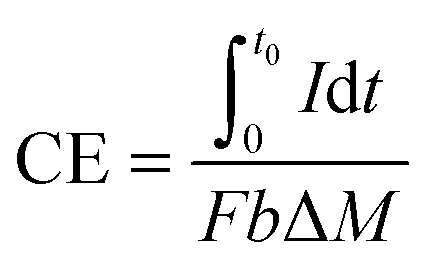 | (7) |
![[thin space (1/6-em)]](https://www.rsc.org/images/entities/char_2009.gif) 485 C per e−1).
485 C per e−1).
For complex wastes, it is more convenient to use COD as a measure of substrate concentration, and the CE thus becomes:
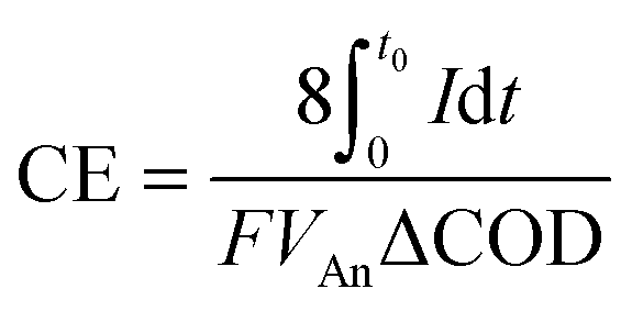 | (8) |
CE is related to electrical current, but a high current does not necessarily result in a great power output. Thus, ECE is proposed to represent the fraction of energy in a fuel cell that is captured as electricity:20
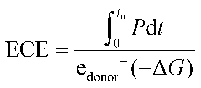 | (9) |
So far, current density and power density have been extensively used in MFC-related studies. However, these two parameters reflect the power output of MFC only, but give no information about the correlation between energy production and waste removal. NER seems to be more appropriate to predict the energy performance of MFC with respect to waste treatment, because it provides energy information that is associated with the waste characteristics.19 Nevertheless, power density is still essential for calculating the value of NER, and a higher power output generally results in a greater NER. CE and ECE are criteria directly related to the waste-to-electricity conversion. CE represents the amount of electrons delivered from wastes in the form of current, and ECE suggests the energetic efficiency that is dependent upon both voltage and current.21 While ECE precisely describes the percentage of electric energy converted from wastes, it does not apply to wastes with unknown compositions, because it is hard to estimate their Gibbs free energy. In this case, NER can be used as an alternative to assess the energy recovery from wastes. Of course, multiple parameters should be comprehensively compared to get a thorough understanding of the energy performance of MFC, and both the power output and energy recovery efficiency should be taken into consideration in efforts to improve the energy-generating capacity of MFC.
3. Energy harvesting from various wastes by MFC
Waste treatment is usually energy and cost intensive.10,22 MFC is an emerging technology that promises direct production of electricity in waste treatment. Various chemicals ranging from small molecular organics to polymers can be used to fuel MFC, making it an ideal technology to extract energy from a variety of wastes.3.1 Domestic wastewater
Modern water management is driving innovations in domestic wastewater treatment technologies with a focus on reducing energy demand and recovering energy, water and other resources. In conventional process of aerobic wastewater treatment combined with anaerobic sludge digestion, a large portion of the energy contained in dissolved organic fraction is not recovered but removed. In comparison, MFC allows a direct energy capture from dissolved organic component in the form of electricity with little offsetting energy expenditure. Especially, MFC has distinct advantages over anaerobic digestion in treating low-strength domestic wastewater.23 The possibility of implementing energy self-sufficient MFC for domestic wastewater treatment has been envisaged based on the performance of liter-scale reactors.17 In a 200 liter MFC stack (effective volume of 100 liter) fed with domestic wastewater, the highest power output of 114 mW was obtained, which is sufficient to drive a direct current (DC) pump (Fig. 2).24 Another 250 liter stackable pilot-scale MFC produced a net power of 0.47 W m−3, while the operation energy cost was only half of that in conventional aerobic treatment.25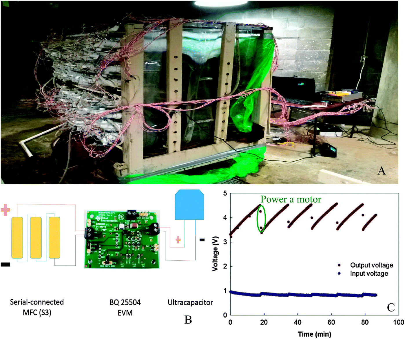 | ||
| Fig. 2 (A) Prototype of a 200 liter MFC stack fed with domestic wastewater; (B) schematic of charging/discharging circuit connection; and (C) charging and discharging of the ultracapacitors to drive a DC motor. When the voltage of the ultracapacitors reaches 4.5 V, they are discharged by powering the motor. When the voltage is lower than 3.5 V, ultracapacitors are disconnected from the motor and charged by the MFC stack until the voltage is 4.5 V (adapted with permission from ref. 24. Copyright 2015 Elsevier Ltd). | ||
3.2 Food wastes
Food processing wastes and food debris are attractive feedstocks for bioenergy production because of the high moisture content, rich organic content and high carbon to nitrogen ratio that favor biodegradation.26 Various food wastes, including canteen based food waste,27 molasses wastewater,28 starch processing wastewater,29 brewery wastewater,30,31 palm oil mill wastewater32,33 and dairy wastewater,34 have been tested as MFC fuels. Wastewaters containing high percentages of easily degradable carbohydrates, such as dairy wastewaters, brewery wastewaters and molasses, are usually more favorable for electricity generation than those rich in celluloses and lipids. An annular single-chamber MFC fed with dairy wastewater was reported to produce as high as 20.2 W m−3 power density along with CE of 26.9%.35 Food waste-fueled MFCs have a great potential for an energy self-sufficient operation in scaled up systems. A 100 liter stackable pilot-scale reactor fed with brewery wastewater in a continuous flow mode produced a total energy of 0.097 kW h m−3, which could be used to power a pumping system (0.027 kW h m−3) for self-sustained feeding (Fig. 3).31 | ||
| Fig. 3 (A) Schematic diagram; (B) photo of the 90 liter stackable baffled MFC fed with brewery wastewater; (C) electrical energy allocation controlled by a float switch. When the liquid level in the head tank falls 1 mm below the height at which the switch is installed, the capacitors are discharged through the pump. When the liquid level rises to the height at which the switch is installed, the energy is harvested by the 5 Ω resistor; and (D) changes of operating voltage across pump and resistance. The maximum voltage on the pump is 4.2 V, which is sufficient to meet the energy requirement for pumping (adapted with permission from ref. 31. Copyright 2015 Elsevier Ltd). | ||
Despite the high energy content of food wastes, their low ion conductivity is a constraint for MFC operation. Generally, power generation of MFCs can be facilitated by a high conductivity of up to 20 ms cm−1,2 whereas most food wastewaters have conductivities typically below 6 ms cm−1.36 Amendment of 100 mM NaCl to the food waste leachate enabled an increase of Pmax from 366 to 1000 mW m−3 because of the increased solution conductivity.37 Food wastes rich in soluble COD sometimes need to be diluted to avoid microbial inhibition, for which low-strength wastewaters such as domestic wastewater is preferred as a dilution medium.38
3.3 Landfill leachate
Landfill leachate generated from the disposal of municipal solid wastes contains a wide range of biodegradable organic matters, xenobiotic organic compounds, sulfide, ammonia and heavy metals. The abundance of organic carbon in landfill leachate makes it a desirable feedstock for MFC. However, the high COD loading and large amounts of poorly biodegradable organics and inhibitory compounds limit the energy production.39,40 So far, power densities of the MFCs fed with landfill leachate were usually less than 1 W m−3, and the CEs were lower than 20%.41–48 In an upflow air-cathode membrane-free MFC, 12.8 W m−3 electricity was produced from landfill leachate, but the CE was 1.2% only.49 Excessively high COD concentration in landfill leachate can decrease the CE, even though it leads to an increased power output. In an MFC fed with young landfill leachate, increasing the COD loading from 1 to 50 g L−1 significantly decreased the CE from 57% to 1%.46 Therefore, when landfill leachate is used to fuel MFCs, a proper dilution is strongly recommended to increase the CE and prevent the depression of power output by inadequate organic loading.3.4 Complex industrial wastes
Recalcitrant compounds comprise a much greater proportion of the total carbon pool than the labile ones. A wide variety of recalcitrant chemicals, such as petroleum hydrocarbons,50,51 chlorinated compounds,52,53 nitrogenous compounds,54 heterocyclic compounds55–57 and polymers,58,59 have been tested as MFC feedstock, but only a few studies used real-field wastes. MFCs exhibited high COD removal efficiencies for the treatment of paper recycling and pharmaceutical wastewater, whereas the power densities were lower than 1 mW m−2.60,61 In comparison, much higher power densities of 8 W m−3 and 822.3 W m−3 were obtained for dye wastewater and steroidal drug industrial effluent, respectively.62,63The use of an electrode as an electron acceptor in soils or sediments is attractive, as the microbes responsible for degradation will co-localize with the contaminants at the anode. Once in position the electrode can provide a continuous long-term electron sink for the biodegradation of harmful environmental contaminants. Microbial electrochemical remediation of petroleum-contaminated soil by an MFC has been demonstrated. Hydrocarbon degradation efficiency was improved from 2% in the open-circuit control to 24% in the MFC with Pmax of 2162 mW m−3.64 The MFC constructed on a hexachlorobenzene-contaminated topsoil also showed a high pesticide removal efficiency of 71.2% with Pmax of 77.5 mW m−2.65
3.5 Sewage sludge
Sludge disposal expenses may account for up to 50% of the total cost for sewage treatment, and hence is a headache for many municipal wastewater treatment plants. Notably, a large amount of energy in wastewater enters into sludge after aerobic treatment process. Thus, sludge is a potential energy source to be exploited.66 To date, the maximum power output of MFCs that use sewage sludge as fuel is 4.2 W m−3 for an abiotic cathode system67 and 13.2 W m−3 for a biocathode one.68 Sewage sludge is mostly present in the form of insoluble particulates, whereas microorganisms in MFCs prefer soluble and easily biodegradable organic matters. As a result, sludge pretreatments with ultrasonication, heating, alkalination or pre-fermentation are recommended to disintegrate the insoluble materials and thus enhance energy recovery efficiency.69,70 Despite the limited electricity generation, MFC is still an attractive technology for energy recovery from sewage sludge because CH4 can be simultaneously produced in the anodic chamber. A two-stage MFC system for sludge treatment achieved a total energy production (sum of electric energy and biogas energy) as high as 23.22 kW h m−3 at a hydraulic retention time of 14 days, which is comparable with that in an anaerobic digester.183.6 Animal wastes
Modern livestock agriculture has drastically increased the production of animal wastes. Manure and urine contain abundant organic matters, and thus can be used as substrates for MFC. Reported power densities of animal waste-fueled MFCs were highly diverse, ranging from several hundred milliwatts to several watts per cubic meter reactor volume. An MFC powered by dairy manure obtained a Pmax of 15.1 W m−3 using a biocathode,71 and 16.3 W m−3 in a cassette-electrode configuration.72 However, in a 4 liter MFC of loop configuration fed with piggery wastewater, the Pmax was 1.416 W m−3 only.73 The power density is affected by the solid and moisture contents in animal wastes. A continuous increase in the solid content from 2% to 10% led to an initial rise and subsequent sharp decrease in power density.71 In another study, animal wastes with moisture contents of 80, 70 and 60% achieved Pmax of 349 ± 39, 36 ± 9 and 12 ± 2 mW m−2, respectively.74 An unfavorable feature of animal wastes is the high concentration of ammonia, which severely inhibits the exoelectrogenic activity.75 Nitrate and nitrite transformed from ammonia also reduce the energy recovery efficiency by competing with the electrode for electrons.73,763.7 Plant wastes
The abundance and renewability of lignocellulosic materials from plant wastes render them a promising feedstock for cost-effective energy production. The feasibility of MFC to use agricultural wastes, including corn stover,77,78 wheat straw,79,80 rice straw,81 bean residue and ground coffee,82 and aquatic plants such as Canna indica,83 as substrates has been evaluated. Lignocellulosic biomass contains abundant cellulose, hemicellulose and lignins, which cannot be directly utilized by exoelectrogens and have to be converted to monosaccharides or other low-molecular-weight compounds first. Therefore, hydrolysis and fermentation of lignocellulosic biomass are needed before it can be used for electricity generation.84 The power output of MFC is generally restricted by the low biodegradability of lignocellulosic materials. As shown in Fig. 4, lignocellulosic materials contain polysaccharides in the form of cellulose and hemicelluloses, which are closely associated with lignin. It is difficult for microorganisms to access cellulose and hemicelluloses unless lignin is modified or removed. Thus, pretreatment aiming at breaking down the rigid structure of lignocellulose is necessary to improve their microbial accessibility.85 Usually the pretreatment gives a carbohydrate-rich liquid hydrolysate by hydrolyzing cellulose and hemicelluloses.77 By using Oscillatoria annae to converting the lignocellulose to glucose, a three-compartment MFC achieved very high Pmax of 8.78 and 6.73 W m−3, with sugarcane bagasse and corn cob as substrates, respectively.86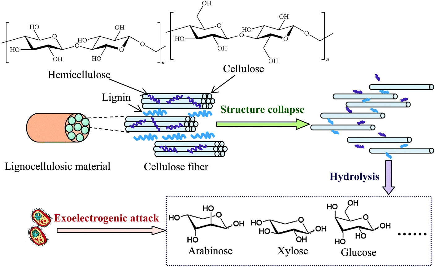 | ||
| Fig. 4 Enhancement of pretreatment on exoelectrogenic accessibility to lignocellulosic materials. | ||
It is difficult to compare performances of MFCs in literature due to the different operational conditions, reactor configurations, types of electrodes and membranes and microorganisms involved. Yet, the potential of MFC to recover electric energy from real wastes can be approximately estimated. As shown in Table 1, the energy-generating capacities of MFCs vary significantly, depending on the composition, strength and solution chemistry of wastes. Differing from single substrate incubation, microbial degradation of complex substrates in real wastes features an energy-intensive process with intricate combination of sequential and parallel substrate degradation routes. As a result, simple wastes rich in biodegradable organics usually yield more energy than those containing complex substrates, refractory compounds or insoluble components.20 Electron losses to competitive electron acceptors such as nitrate, nitrite and sulfate can impair energy recovery from wastes. Compounds that inhibit the exoelectrogenic activity should be removed or converted because they can reduce the power output of MFC.
| Type of waste | Reactor configuration | Reactor volume (L) | Maximum power density | Maximum CE (%, based on COD) | Ref. | |
|---|---|---|---|---|---|---|
| Normalized by anode volume (W m−3) | Normalized by anode area (W m−2) | |||||
| Urban wastewater | Two-chamber MFC | 1 | 0.025 | 87 | ||
| Domestic wastewater | Membrane electrode assembly MFC | 3.5 | 2 | 0.9 | 88 | |
| Domestic wastewater | Multi-anode/cathode MFC | 20 | 1.500 | 89 | ||
| Domestic wastewater | MFC stacks (parallel connected) | 1.872 (156 mL per unit) | 248 | 77.8 | 90 | |
| MFC stacks (series connected) | 228 | 12.4 | ||||
| Palm oil mill effluent | Upflow membrane-less MFC | 2.36 | 0.0446 | 32 | ||
| Ultrasonically pretreated palm oil mill effluent | Two-chamber MFC | 4 | 18.33 | 18.96 | 91 | |
| Brewery wastewater | Serpentine-type MFC stack | 10 (250 mL per unit) | 6.0 | 7.6 | 92 | |
| Brewery wastewater | Baffled MFC | 100 | 0.181 | 19.1 | 31 | |
| Sugar refinery wastewater | Single-chamber MFC | 1 | 1.495 | 5.37 | 93 | |
| Protein food industry wastewater | Two-chamber MFC | 1.5 | 0.2303 | 15 | 94 | |
| Cassava mill wastewater | Single-chamber MFC | 30 | 1.800 | 20 | 95 | |
| Acidogenic food waste leachate | Two-chamber MFC | 3 | 15.14 | 66.4 | 96 | |
| Landfill leachate | Single-chamber MFC | 1 | 0.0018 | 41 | ||
| Landfill leachate | Two-chamber MFC | 1 | 0.00135 | 42 | ||
| Landfill leachate | Single-chamber circle MFC | 1.89 | Insignificant | 5.2 | 48 | |
| 1 | 0.844 | 41 | ||||
| Landfill leachate | Membrane-less MFC | 3.5 | 2.71 | 97 | ||
| Sewage sludge | Two-chamber MFC | 1 | 45.34 | 0.04534 | 98 | |
| Sewage sludge | Membrane-less | 1 | 2 | 0.29 | 99 | |
| Primary sludge | Tubular MFC | 1.8 | 6.4 | 7.2 | 18 | |
| Digested sludge | 3.2 | 2.6 | ||||
| Primary sludge | Two tubular MFCs (series connected) | 1.8 |
8.5 (MFC1)
10.7 (MFC2) |
2(MFC1)
4(MFC2) |
||
| Thermo-chemical pretreated dairy waste activated sludge | Two-chamber MFC | 1.35 | 0.715 | 9 | 100 | |
| Animal carcass wastewater | Up-flow tubular air-cathode MFC | 1.2 | 2.19 | 0.25 | 101 | |
| Swine wastewater | MFC stacks (parallel connected) | 1.475 (295 mL per unit) | 175.7 | 0.1 | 102 | |
| Cattle manure solid waste | Twin-compartment MFC | 1.8 | 0.3 | 0.093 | 103 | |
| Cattle dung | Two-chamber MFC | 15 | 0.22 | 2.79 | 104 | |
| Piggery wastewater | Loop configuration MFC | 5 | 0.0014 | 73 | ||
| Chemical wastewater | Two-chamber MFC | 1.5 | 2.02 | 105 | ||
| Mixture of domestic wastewater and real textile wastewater | Membrane-less cross-linked MFCs | 4 (2 L per unit) | 750 | 36 | 106 | |
| Bermuda-grass straw | Two-chamber MFC | 2 | 0.00000309 | 107 | ||
| Avena L. straw | Soil MFC | 0.0108 | 108 | |||
| Acorus calamus leaves | Sediment MFC | 0.195 | 109 | |||
| Wheat straw | 0.167 | |||||
Acknowledging that many real wastes may not be suitable for directly fueling MFC from an energy production perspective, there are opportunities to lift the energy-generating capacity of waste-fed MFCs through improving the biodegradability of wastes and eliminating inhibitory and competitive compounds by pretreatment. Currently the average NER of MFCs fed with domestic wastewater is 0.04 kW h m−3 wastewater or 0.17 kW h kg−1 COD, and industrial wastewater results in a value of 0.10 kW h m−3 wastewater or 0.04 kW h kg−1 COD.19 This NER level is quite low compared to the value of 0.34–0.49 kW h m−3 wastewater or 0.69–0.98 kW h kg−1 COD obtained by the conventional anaerobic digestion approach.10 However, till date the highest NER observed in the MFCs is above 2.0 kW h m−3 wastewater or 1.95 kW h kg−1 COD.19 It is anticipated real waste-fed MFCs might achieve such an NER target after appropriate pretreatment to facilitate the waste degradation in MFCs. In addition to the energy recovery efficiency, the power output of MFCs with real wastes also remains to be promoted. The power density of MFC should achieve 1 kW m−3 to be competitive to anaerobic digestion,110 while most real waste-fueled MFCs have power densities below 10 W m−3 (Table 1). Nevertheless, it is desirable to improve such power density to hundreds of watts via pretreatment, in the light of the highest power density of 200 W m−3 obtained in a 4 liter MFC with acetate as the substrate.111,112
4. Factors constraining energy output of MFC
4.1 Thermodynamic limitation and energy losses
Progresses in reactor architecture, material and operation optimization of MFC have remarkably relieved physical and chemical constraints of MFC systems. However, the true power generation potential of MFC is still limited by the thermodynamic barrier and the high energy losses. Unlike chemical fuel cells, large power production cannot be easily achieved by simply connecting MFCs in series or parallel due to their nonlinear nature.113–115 Up to now, the highest power density of a single liter-scale MFC is reported to be 200 W m−3,111,112 which is several orders of magnitude lower than those achieved by many other energy conversion technologies (Fig. 5a).116 Even if the power of MFC is proportionally improved to the reactor volume, the maximum power output of a 1000 m3 MFC will be no more than 0.2 MW, which is still insufficient to meet local power needs as a stationary power supply (Fig. 5b).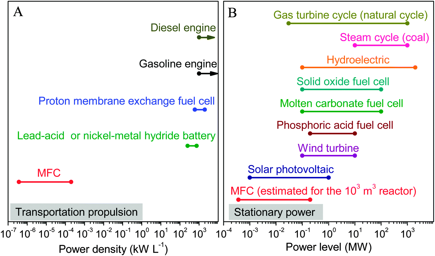 | ||
| Fig. 5 Comparison of: (A) power density; and (B) power level between MFC and other energy conversion devices in transportation propulsion and stationary power sectors (data are obtained from ref. 111, 112 and 116). | ||
 | ||
| Fig. 6 Schematic of the electron transfer process at the anode of MFC with sequential energy losses. | ||
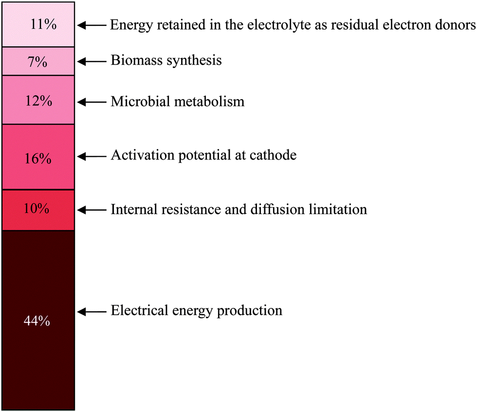 | ||
| Fig. 7 Energy recovery in a glucose-fed microbial battery with an Ag2O/Ag solid-state cathode (adapted with permission from ref. 120. Copyright 2013 PNAS). | ||
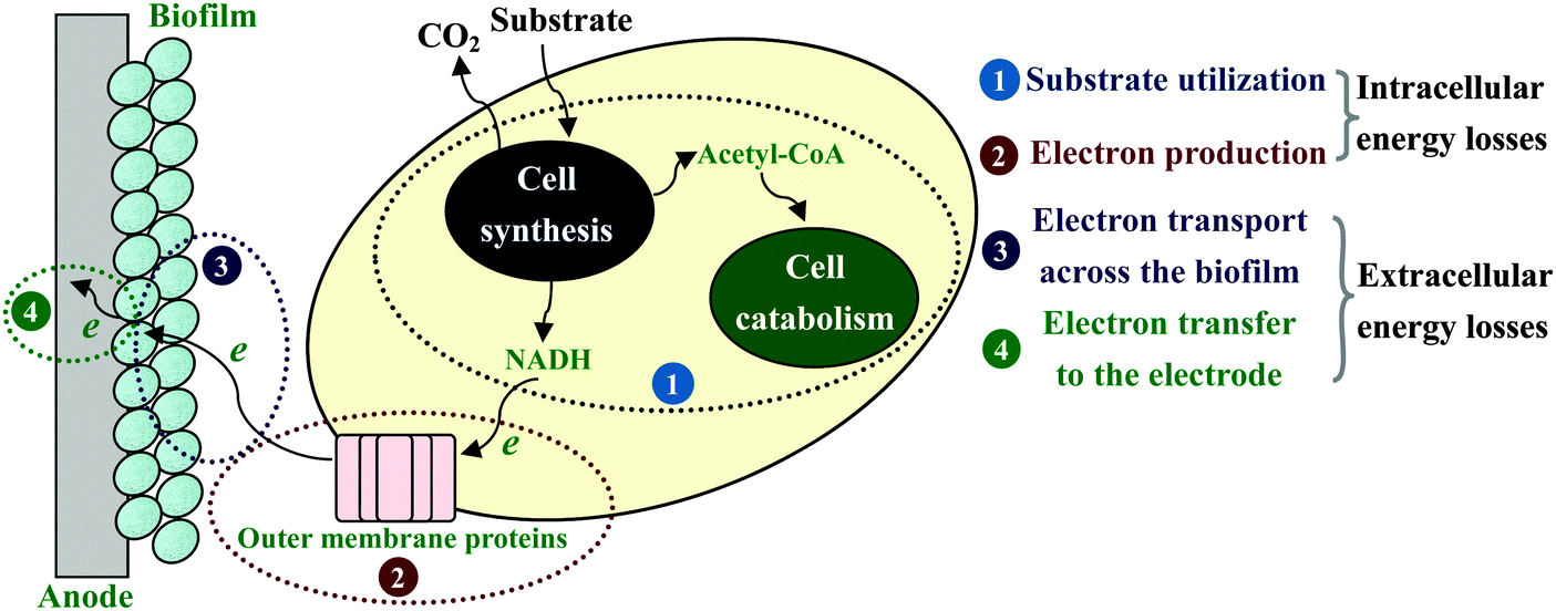
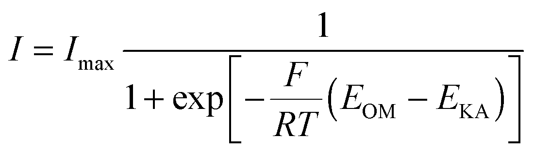
Electrochemical reactions at the electrode surface require activation energy for the electron transfer either from the electron donor to the anode or from the cathode to the electron acceptor. Energy losses at the anode of MFC are different from those for a chemical fuel cell, because the formation of the anode-biofilm creates a unique environment. First, microbial metabolism involves energy loss. Microbes must capture energy from the potential difference between their electron donor and terminal electron carrier to support their growth and maintenance. Second, biofilm has its own ohmic resistance for electron conduction from microbial cells to the anode surface, and mass transport within biofilm also consumes energy.20 Both the intracellular and extracellular energy losses in substrate consumption and electron transfer within anode biofilm have been identified.117 As shown in Fig. 6, two kinetic processes are involved in the intracellular energy losses from substrate to the outer-membrane proteins. At first, substrate oxidation produces intracellular reducing power, which takes the form of electron carriers such as NADH. Then, the electron carrier is oxidized by transferring electrons to outer-membrane proteins. The relationship between the substrate utilization and the current generation fits the Monod equation (eqn (10)), and the Nernst–Monod equation (eqn (11)) could be used to describe the electron transport from reduced intracellular carrier to outer-membrane proteins:121
 | (10) |
 | (11) |
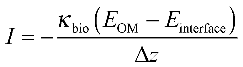
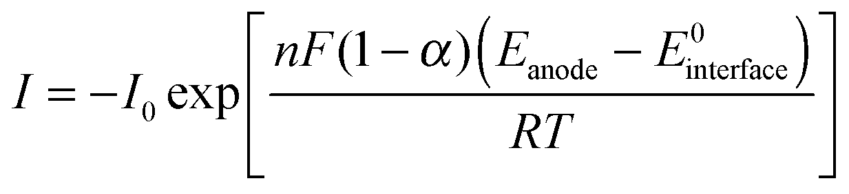
The extracellular energy losses also involve two kinetic processes: one is the electron transport from outer-membrane proteins to the anode surface through the conductive biofilm matrix; another is the electron transport from the biofilm to anode electrode. The electron transfer within the biofilm is restricted by the biofilm conductivity as described by Ohm's law (eqn (12)), and the electron transfer at the electrode interface is modeled by the Butler–Volmer equation (eqn (13)):
 | (12) |
 | (13) |
From eqn (10)–(13), the factors restricting current generation at the anode (i.e., causing energy losses in electron transfer from substrate to anode electrode) could be identified. So far, most efforts in MFC improvement have focused on engineering better fuel cell architecture and/or materials with the implicit assumption that energy loss at the anode biofilm is of negligible impact on the energy-generating capacity of MFC. In fact, there may be large opportunities to improve power production by overcoming the biological limitations.122 A study on Geobacter sulfurreducens showed a direct correlation between biofilm conductivity and current density, clearly suggesting that the energy loss at the anode biofilm is an important factor limiting the power output of MFC.123 In particular, for the real-waste fueled MFCs the minimization of anodic losses is as important as minimization of cathodic losses, because of the interplay between the anode and cathode electrodes.124 It should be noted that substrate losses to other electron sinks, such as methanogenesis, nitrate- and sulfate-reductions, H2 scavenging and aerobic microbial growth, can significantly reduce the energy recovery efficiency of MFC in practical waste treatments.125
At the cathode electrons are transferred to terminal electron acceptor. This process is currently recognized as the bottleneck confining the energy output of MFC (Fig. 8).126 In analogy to other chemical and biological fuel cells, the cathode activation loss is mainly due to the high energy barrier for O2 reduction.127 The O2 electro-reduction is a complex process involving several electrons and many possible pathways. In the past decades great efforts have been made to improve catalyst efficiency and reaction kinetics, whereas the overpotential for cathodic O2 reduction is still substantial. Particularly, the activation energy for O2 reduction is positively correlated to the electrode potential according to ab initio molecular dynamics based on a four-step pathway (eqn (14)–(17), Pt atom is used to coordinate with O2, HO2˙, H2O2 and HO˙) (Fig. 9A).128
| Pt–O2 + H+ + e− → Pt–OOH | (14) |
| Pt–OOH + H+ + e− → Pt–OHOH | (15) |
| Pt–OHOH + H+ + e− → Pt–OH + H2O | (16) |
| Pt–OH + H+ + e− → Pt–OH2 | (17) |
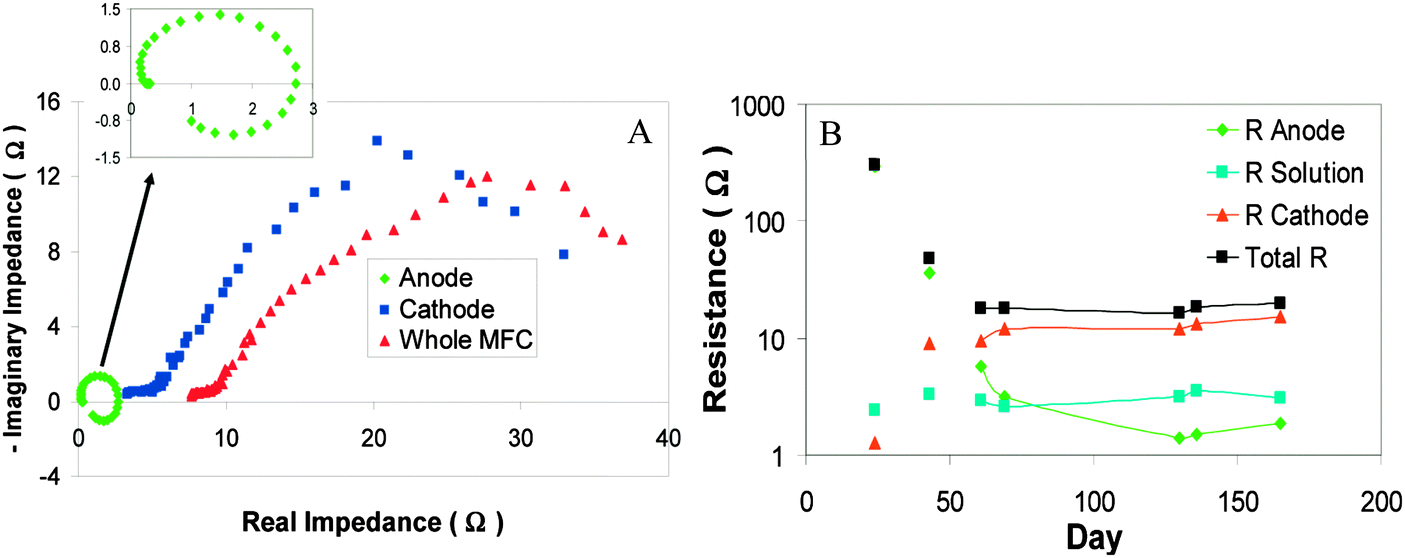 | ||
| Fig. 8 (A) Nyquist plots showing a significant contribution of cathode impedance to the total impedance of MFC; and (B) behaviors of anode, cathode and solution membrane impedance over time during the enrichment of exoelectrogens in the MFC (Reprinted with permission from ref. 126. Copyright 2010 American Chemical Society). | ||
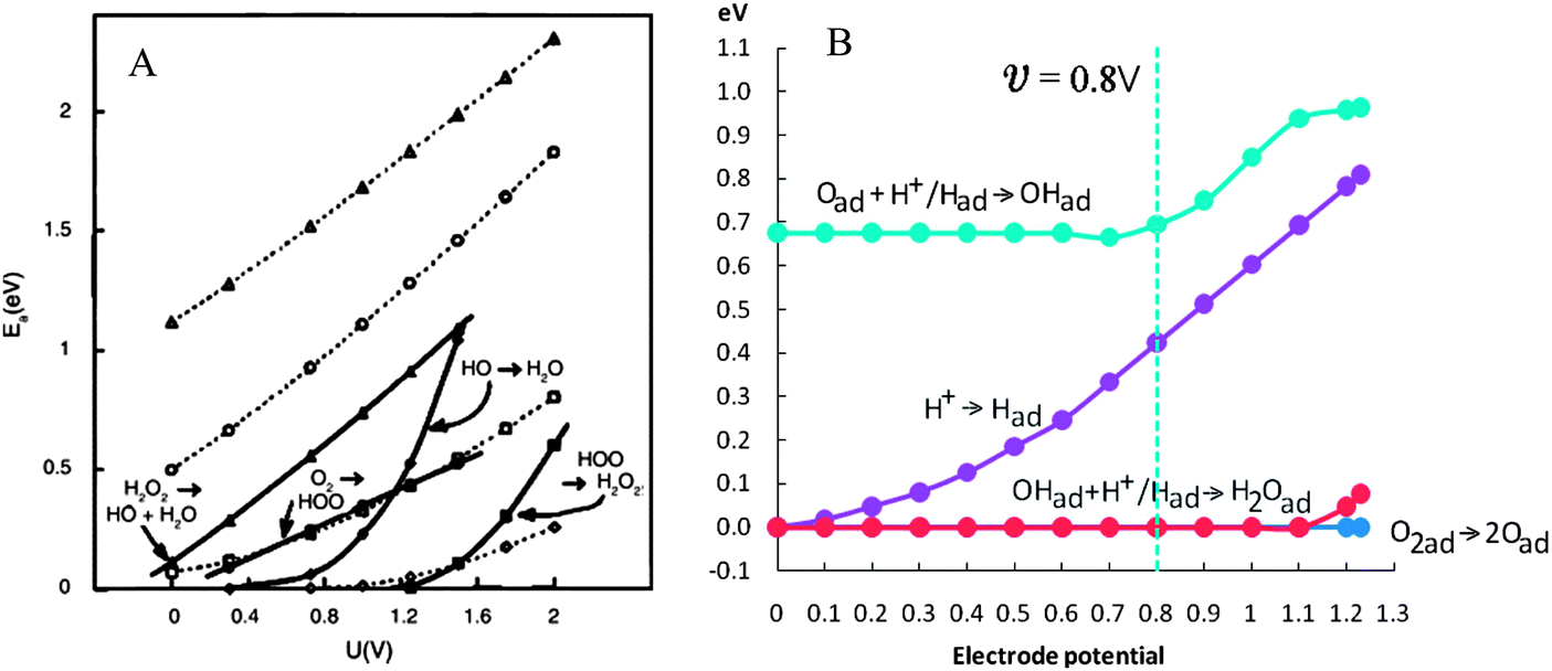 | ||
| Fig. 9 (A) Activation energy for the four steps of O2 reduction as a function of electrode potential. Heavy lines connect points with species undergoing reduction bonded to a platinum atom. Dotted lines connect points with no bonding to the platinum. The same key applies to both sets of curves; and (B) energy barriers for the O2 reduction calculated by density functional theory (Reprinted with permission from ref. 128 and 129. Copyright 2000 The Electrochemical Society, Inc. and 2012 American Chemical Society). | ||
Similar results are obtained from density functional theory calculations for O2 reduction following another reaction cycle on the Pt(111) surface (eqn (18)–(21)). The energy barrier increases monotonically with increasing electrode potential (Fig. 9B).129
| H+ + e− → Pt–H | (18) |
| O2gas → Pt–O2 → 2Pt–O | (19) |
| Pt–O + (H+ + e−)/Pt–H → Pt–OH | (20) |
| Pt–OH + (H+ + e−)/Pt–H → Pt–OH2 | (21) |
Therefore, in the presence or absence of catalyst, more activation energy is required to obtain a high cathode potential. Even worse, many chemical catalysts suffer from much poorer catalytic performance in MFC than in chemical fuel cells due to the suboptimal operational conditions, resulting in more energy lost at the cathode.130 In addition, mass transport limitation in the cathode compartment is typically more severe than that in the anode compartment because of the low solubility of O2 in water.131 For a biocathode, bacterial growth and mass transfer within the biofilm also contribute to the energy losses.
The separating membrane between the anode and cathode assures a high selectivity for protons and environmental stability for bacteria growth, but it also causes substantial energy loss. Membrane resistance originating from the low accessibility of liquid electrolytes onto the membrane surface is identified as the primary internal resistance of MFC. In electricity generation processes, electron transfer through the circuit is accompanied by ion diffusion across the membrane to maintain electroneutrality. Insufficient ion transport through the membrane not only causes an increase in membrane resistance, but also leads to pH-splitting problem, i.e., acidification of the anodic side and alkalization of the cathodic side.132,133 In general, anion exchange membranes suffer from less energy loss caused by pH-gradient than cation exchange membranes, but are more prone to substrate permeability and deformation.134,135 Compared with ion exchange membranes, size-selective separators, such as microporous filtration membranes, porous fabrics, glass fiber and nylon mesh, usually show higher ion transport ability and lower internal resistance.93,134,136–138 However, the CE is concomitantly reduced as a result of the increased substrate and O2 permeations through the separator pores. While the development of MFC separator seems to be confronted with a dilemma between charge transfer and mass permeation,139 several emerging approaches show a potential to alleviate such a problem. Proton conductance across ion exchange membranes can be facilitated by introducing hydrophilic material into membrane structure, thus raising both the power output and CE of MFC.140,141 Separator electrode assembly configuration with porous separator and electrode bound together is found to prevent substrate and O2 permeations through the porous separator, leading to an increased CE.142,143 Osmotic MFCs with forward osmosis membrane exhibit promising electricity generation by making use of water flux to accelerate ion transport and keep O2 out of anode.144,145 Forcing electrolyte to flow continuously from the anode chamber to the cathode chamber is also effective to promote proton flow while limiting O2 diffusion in a two-chamber MFC.146 At the present stage, the poor separator performance is still a major barrier limiting the energy output from MFC, and there is much to be done to reduce the separator-induced energy loss.
Electrolyte resistance coming from ionic flow through the electrolyte determines the energy loss associated with mass and charge transport in solution. Such an energy loss can be reduced by increasing solution conductivity, while the susceptibility of bacteria to the added electrolytes should be taken into consideration. In comparison, reducing the electrode spacing can decrease the mass diffusion distance and is a more feasible option to reduce the electrolyte resistance.111,147,148
4.2 Instability of power output
Stable power output is an essential requirement for an electricity generator. However, the poor longevity of MFC severely restricts its potential as a direct power supplier. As shown in Fig. 10, MFCs after long-term operation, especially those fueled with real wastes, inevitably suffer from performance deterioration with severe fluctuations in the power output.149 To date, some attempts have been made to resolve this problem, but truly effective and practical countermeasures are still lacking.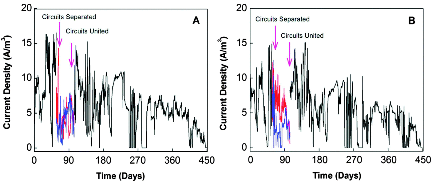 | ||
| Fig. 10 Current profiles of 4 liter tubular MFCs installed in a municipal wastewater treatment facility: (A) with activated carbon powder as catalyst at cathode; and (B) with both the activated carbon powder and Pt as catalyst at cathode (Reprinted with permission from ref. 149. Copyright 2013 American Chemical Society). | ||
 | ||
| Fig. 11 Internal factors responsible for performance decline of MFC. | ||
The O2 reduction reaction catalyzed by chemical catalysts (usually Pt) is the most dominant cathodic reaction in MFC. The unlimited availability and high standard redox potential of O2 in air make it an ideal electron acceptor, but chemical catalysts for O2 reduction suffer from performance decay during long-term operation. Power output was found to drop by 21% when a biofilm was formed on the Pt-catalyzed carbon cloth cathode, and removal of the cathode biofilm completely restored the power output to its original level (Fig. 12A).164 Here, the formation of a cathode biofilm blocked the proton transfer to the catalysts.165,166 However, in addition to biofilm, other factors can also cause cathode deterioration. Pores in the cathode could be clogged over time, resulting in raised O2 diffusion resistance.167 Owing to the accumulation of alkali salt and low air humidity at the cathode side, a 10 liter MFC stack treating brewery wastewater exhibited a 60% decrease in Pmax during the incubation period from 30 to 180 days (Fig. 12B).92 Biocathodes seem to be more stable than chemical ones in the over 400 day operation of MFCs.168 However, in practical waste treatment, biocathodes may suffer from more severe deterioration because of microbial susceptibility.
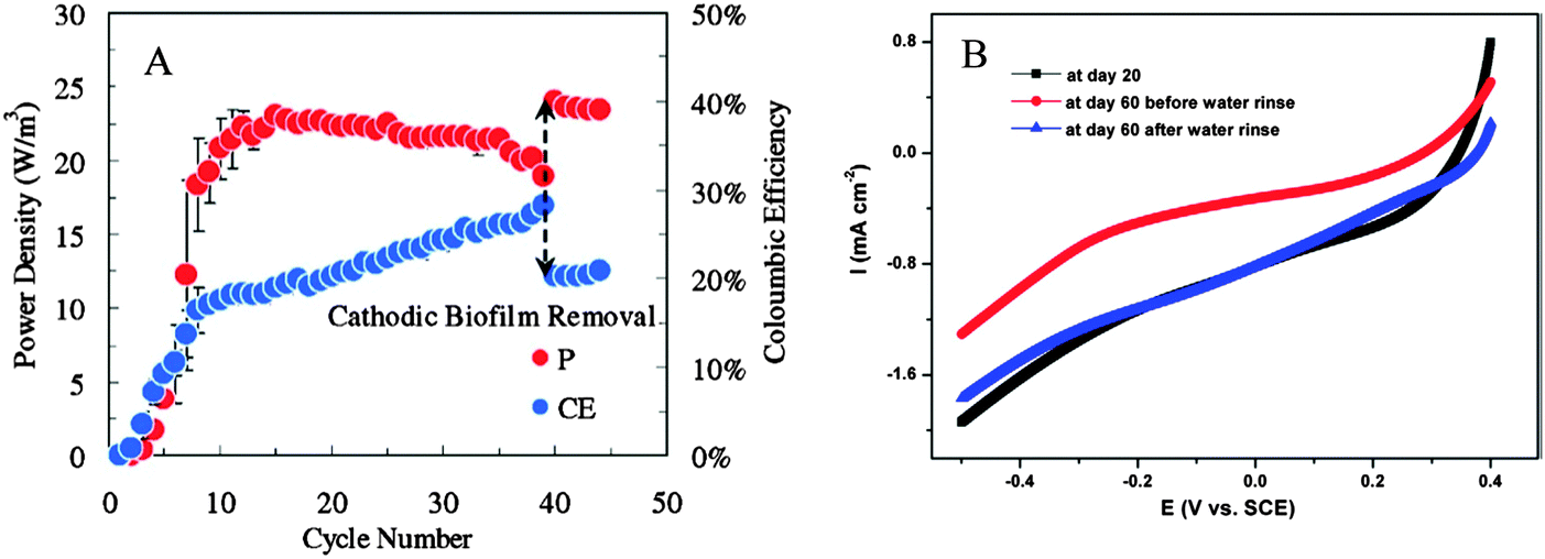 | ||
| Fig. 12 (A) Power density (P) and coulombic efficiency (CE) of MFC influenced by the growth of cathode biofilm; and (B) linear sweep voltammetry of cathode showing the performance deterioration due to cathode clogging by alkali salts from day 20 to day 60. The current is retrieved after the salt is removed by water rinse (Reprinted with permission from ref. 92 and 164. Copyright 2012 Elsevier Ltd and 2009 American Chemical Society). | ||
The inevitable membrane fouling during long-term operation of MFC can significantly deteriorate its power generation performance. Accumulation of high-valent ions in membrane pores would block ion transport channels and raise electrical resistance. It was found that, after 400 day operation, the power density of a two-chamber MFC dropped by 26.6% due to the hindrance of ion transport by cations inside the membrane.169 Biofouling due to the formation of biofilm on the membrane surface can significantly deteriorate the membrane performance. The fouling layer, which consisted of microorganisms encased in extracellular polymers and inorganic salt precipitations, was found to lower the ion exchange capacity, conductivity and cation diffusion coefficient of a proton exchange membrane (Fig. 13). As a result, the internal resistance of MFC was remarkably increased by 20% and the open circuit voltage was reduced by 9.9%, leading to a 32.3% decline in Pmax.170
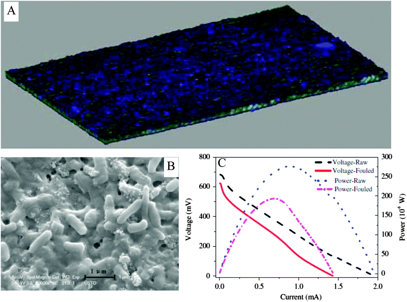 | ||
| Fig. 13 (A) Reconstructed three-dimensional image of the fouling layer on the proton exchange membrane after 90 day operation of MFC; (B) bacteria in the fouling layer; and (C) decreases in power and voltage of the MFC due to biofouling (adapted with permission from ref. 170. Copyright 2012 Elsevier Ltd). | ||
The use of real wastes as fuel and mixed microorganisms as catalysts brings about inherent constraints to the energy conversion in MFCs. Although higher electricity-generating ability of exoelectrogens may be expected in the future, currently the power output of individual MFC is still too low to compete with other energy conversion devices. In addition, the unavoidable performance deterioration over time and power fluctuation of MFC increase the difficulty in achieving reliable power supply. In the light of experiences from other renewable sources such as wind and marine current energy, introduction of an energy storage device into circuit is assumed to be a good solution to boost the power output, mitigate the power fluctuation and improve the power quality of MFC.183,184
5. Energy capture and storage with MFC
At present the direct power output of MFC or MFC stacks is not sufficient and stable enough to support continuous operation of any commonly used electric appliance. Thus, how to virtually utilize the MFC energy for real-world application remains a main challenge. To harvest usable MFC energy, it is necessary to integrate devices that can capture and store energy and boost the power output of MFC. Power converter-based energy storage devices have been recently explored to replace external resistors that are utilized to deliver the power output of MFC.185 The electronic circuit can operate as an equivalent external resistor, but energy generated from MFC can be harvested in storage instead of being dissipated as heat.186–1885.1 Energy storage technologies for MFC
At present, electrochemical capacitors are predominantly applied to deposit MFC energy for driving low power-consumption instruments.24,31,188–193 An electrochemical capacitor is a typical energy storage device composed of two conductive terminals separated by a dielectric material. The charge-storage of a capacitor is completed predominately by utilizing a double-layer charging effect, but pseudo-capacitance also partially contributes to this process. Now capacitors capable of quickly absorbing or liberating a high amount of energy during hundreds of thousands of cycles without the release of heat and hazardous substances have been developed. The main advantage of a capacitor lies in its efficacy to smooth high-frequency power fluctuations, thus improving power quality.184Through alternate charging and discharging, the outputs of current, voltage and power from MFC can be multiplied. Since capacitors stop charging when the voltage reaches the open circuit voltage value, MFC stacks and multiple capacitors are used to boost the power output. By charging an array of parallel-connected capacitors from four MFCs and then discharging them in series, the output voltage was found to increase from 0.7 to 2.5 V, meanwhile peak power was improved by 2.6 times with negligible energy loss in the circuit.194 When a capacitor was integrated with an MFC anode by using a capacitive electrode, exoelectrogens growing on the capacitive electrode can directly transfer the produced electrons to the electrode for storage.195–197 Such an electrode design is able to improve the power output of MFC, while the energy storage capacity remains to be improved in comparison to an external capacitor.
A superconducting magnetic energy storage system stores energy in the magnetic field created by a flow of direct current in a superconducting coil (inductor). It is the only known technology to store electrical energy as current circulating through a coil that is made from a superconducting material and is able to circulate indefinitely. Once the superconducting coil is charged, the current will not decay and the magnetic energy can be stored. The magnetic energy storage system can harvest 67% energy from MFC.198 Although the implementation of magnetic energy storage device is costly, the minimal amount of energy loss and high quality of power output make it an attractive option for the MFC energy storage.199
5.2 Capacitor-based power management system
The use of a capacitor cannot produce a continuous power output, but it does allow an intermittent supply of higher power. This is acceptable, especially for some environmental monitoring sensors that are operated in an intermittent mode. In such a case, a capacitor is usually used together with a charge pump, a boost converter and load, constituting a power management system (Fig. 14). The charge pump draws a low current from the MFC to charge the capacitor, while the boost converter is used to lift the output voltage of the capacitor to the voltage level of the load.200 The power management system has been proven useful to assist benthic MFCs as a long-term power source for remote sensors.189–192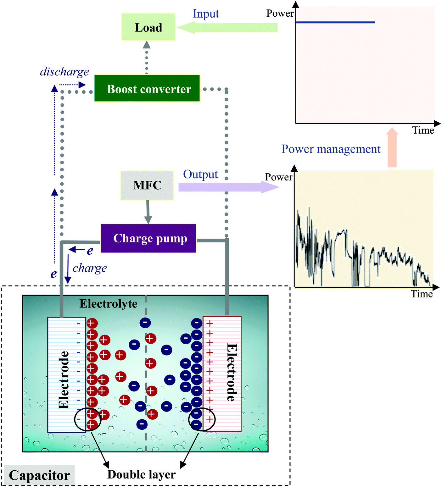 | ||
| Fig. 14 Capacitor-based power management system for energy harvesting from MFC. | ||
Another application pattern of the circuitry is the self-sustainable MFC stack. An MFC stack made from 40 identical 20 mL units of single-chamber 3D-printed MFCs was developed to perform its daily regime of feeding, hydration, self-sensing and reporting by using its own power.188 Electricity generated from this MFC stack was used to continuously run a microcontroller for self monitoring and reporting the voltage of the stack and environmental temperature every 10 min. It was also used to simultaneously charge a 12.5 F supercapacitor pack to power the anolyte feeding of the stack at 48 h intervals and catholyte hydration at 12 h intervals. When the MFC stacks are scaled up their power output is able to run electric devices such as DC pumps. The power of an MFC stack composed of 24 tubular MFCs with a 2 liter working volume was charged into 25 F ultracapacitors through a battery management evaluation module (EVM) board (Fig. 2).24 The output voltage of the ultracapacitors was stabilized at 3.5–4.5 V to power the DC pump while the input voltage was only 1 V. A self-powered active-feeding pattern has been demonstrated by a 100 liter brewery wastewater-fed MFC stack with five capacitor-based circuits charged in parallel and discharged in series (Fig. 3).31 Notably, the energy consumption for pumping was less than half of the total energy produced by the MFC, thus enabling extended functionality with excess energy. Recently, a 6 liter MFC was constructed which harvested 0.27 kW h m−3 energy from synthetic wastewater with COD of 1000 mg L−1. By using a circuit made up of 3.3 F capacitors and relays controlled by a programmable microcontroller, the generated energy was used to power both the pumping system for MFC (at energy consumption of 0.014 kW h m−3) and another intermittent aeration system for a biological filter (at energy consumption of 0.22 kW h m−3).201 By virtue of a power management system, more durable power is conceivable from large-scale MFC stacks to drive electric appliances in waste treatment plants.
To date almost all reported power management systems for MFC energy harvest have been focused on DC output to power small electronic devices. However, general electrical appliances in waste treatment require alternating current (AC) power to operate, which raises the need to develop energy management systems that are able to conduct DC–AC power conversion for large-scale MFCs. A DC–AC converter that can generate alternating voltage in any desired frequency at ≥95% efficiency was recently developed.202 However, how to incorporate such a converter with a capacitor remains a challenge.
The circuit with a resistor connected between anode and cathode indicates the amount of power that can be continuously supplied by an MFC, but it does not capture any usable energy. When an MFC is connected with a capacitor as an energy storage device, traditional evaluation criterions based on the circuit with an external resistor are no longer suitable. Alternatively, the circuit should be evaluated in terms of energy harvested by a capacitor.203 Specifically, information on the capacitor value, the charging potential allowing maximum energy harvest and the charging frequency achieving a desired charging potential will be important for the system performance evaluation.
Presently, studies on power management systems for MFC is in its infancy. There are a variety of electrical energy storage technologies, including capacitor energy storage, superconducting magnetic energy storage, battery energy storage, flywheel energy storage, pumped hydro-energy storage and compressed air energy storage, available for energy systems at different power scales. Capacitors are presently the most suitable candidate for energy storage with a consideration of the present power level of MFC, yet their performance as a long-term energy storage device for large-scale MFCs is still to be evaluated. Other energy storage technologies should also be tried to adapt to the development of MFC and to fulfill diverse application demands.
6. In situ utilization of energy generated in MFC
Since the power output of individual MFC cannot continuously drive common electronics, in situ utilization of the electrical energy generated from MFC has to be considered. There have been several systems developed so far using the MFC platform with different functions or system constructions (Fig. 15).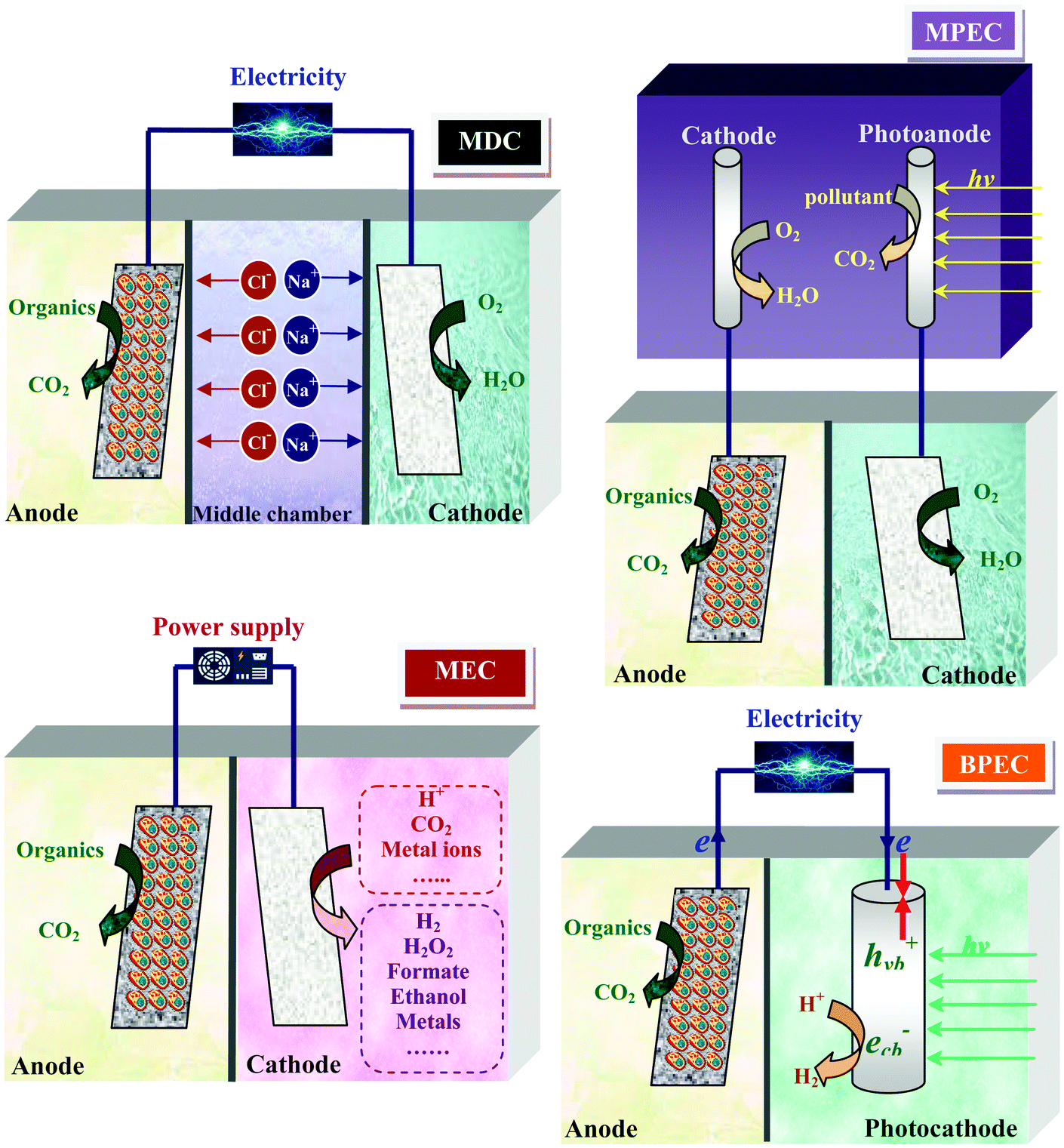 | ||
| Fig. 15 Principles for the in situ utilization of power generated in MFC for various applications. | ||
6.1 Microbial electrolysis cell (MEC)
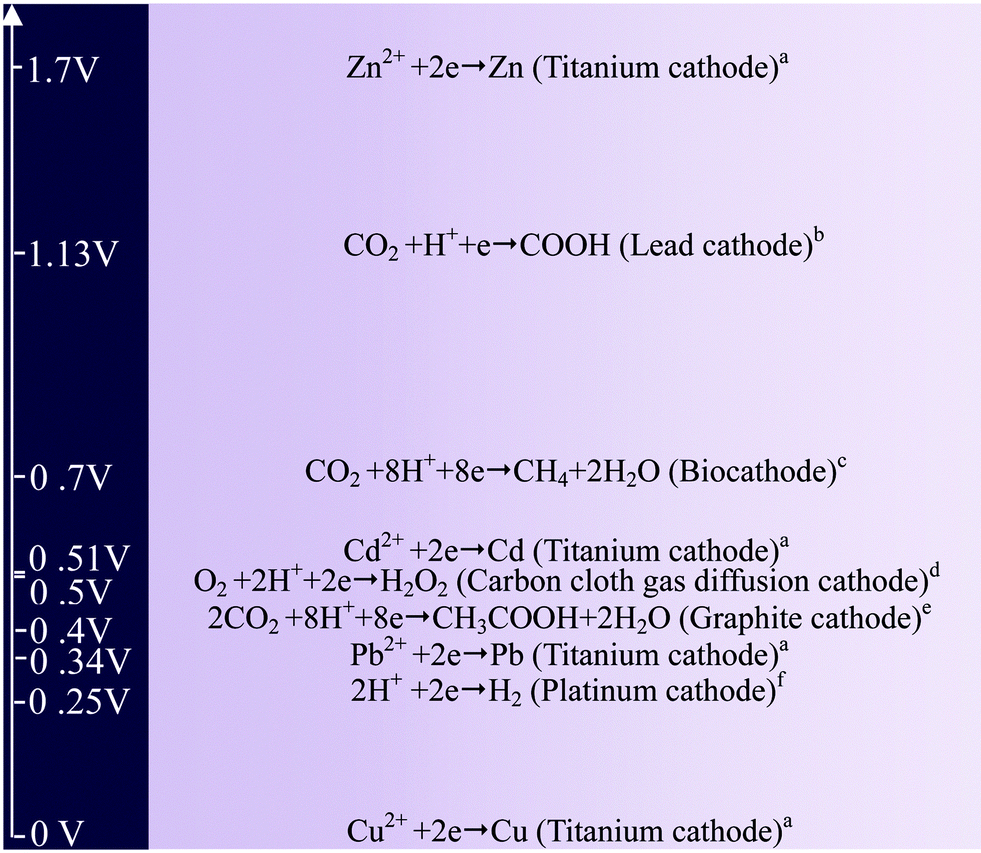
MFC can be operated in a “microbial electrolysis cell” (MEC) mode, in which power originated from the anode is invested to drive thermodynamically unfavorable reactions at the cathode. A typical application is the use of an external voltage higher than 0.25 V on top of the MFC potential to initiate H2 evolution at the cathode through reduction of protons.204,205 Such a voltage is much lower than that used in traditional water electrolysis (1.8–2.0 V). Notably, an MFC can be connected with an MEC to satisfy extra power demand. In an MEC-MFC-coupled system, bioenergies from the anodes of MFC and MEC were integrated to overcome the thermodynamic barrier from protons to H2, thus realizing H2 harvesting from wastes.114,206Similar strategies can be used to produce other chemicals in the cathode chamber. Fig. 16 illustrates the external voltages applied to trigger the synthesis of various chemicals at the cathode reported in literature. The production of CH4 and organic acids such as formic acid and acetate was achieved in a process which utilized the electrons from the anode to reduce CO2.207–209 The feasibility of producing cathodic hydrogen peroxide (H2O2) through a two-electron pathway of O2 reduction combined with the microbial oxidation of organics at the anode was also demonstrated.210 Under an external voltage of 0.5 V, this system was capable of producing H2O2 from acetate with an efficiency of 83%. Since H2O2 generated at the cathode is apt to self-decompose in water, it is proposed to be in situ utilized to degrade biorefractory pollutants under the catalysis of ferrous iron.211 The energy of an MFC can also be utilized for metal recovery from waste streams. Metals with high reduction potentials are directly recovered at the cathode and those with low reduction potentials are recovered with the aid of an external power supply. To recover Cu, Pb, Cd and Zn from wastewater, external voltages of 0, 0.34, 0.51 and 1.7 V were required, with corresponding energy consumptions of 0, 3.8, 7.7 and 283.9 kW h kg−1 metal, respectively.212
 | ||
| Fig. 16 External voltages applied for the production of various chemicals (data are obtained from ref. 212a, 209b, 207c, 210d, 208e and 204f). | ||
6.2 Microbial desalination cell (MDC)
The concept of an MDC is established by making use of the chemical energy stored in organic matter to create a potential gradient across the anode and cathode to drive desalination.213 A typical MDC unit consists of an anode chamber responsible for organic degradation and electricity production, a middle chamber for ion separation and a cathode chamber for completing the electric loop (Fig. 15). In contrast to other water desalination techniques that require power input, the MDC technology is advantageous for extracting pure water from seawater and meanwhile gaining net energy from wastewaters. For example, a liter-scale upflow MDC produced an energy of 1.8 kW h, accompanied by reducing 90% of salinity from 1 m3 of seawater. In comparison, the recovery of 50% water in a reverse osmosis system consumed 2.2 kW h energy.2146.3 MFC-assisted photoelectrocatalytic (MPEC) system and bio-photoelectrochemical cell (BPEC)
Photocatalytic oxidation is a promising process for degrading organic pollutants, but it suffers from recombination of photogenerated electrons and holes, which severely depresses the photocatalytic efficiency. This problem was resolved by connecting a photocatalytic system with an MFC to supply external anodic bias.215 Notably, pollutant degradation rate in this integrated system was twice the sum of the rates by individual photocatalytic and electrochemical methods, indicating that the MFC and photocatalytic system were enhanced by each other.Bioelectricity generated at an anode can also be used to assist H2 evolution at a photocathode. A self-bias BPEC with an MoS3-modified silicon nanowire photocathode was constructed to realize spontaneous H2 production and electricity generation under visible light illumination.216 In such a system, photogenerated holes in the valence band of the semiconductor cathode were trapped by electrons coming from the bioanode, while the photo-excited electrons were combined with protons to form H2. In this way, recombination of the electrons and holes generated under illumination were effectively retarded, resulting in favorable H2 production.
The functions of MFC have been extensively expanded in the above systems, which share microbial oxidation reaction at the anode while harnessing electron flow to satisfy various purposes. The advantage of these systems is that the electrical energy generated at the anode is in situ utilized with a minimum energy loss. However, it should be noted that such an in situ utilization strategy requires an integration of MFC with other energy-consuming processes, which may introduce additional impacts on the anode and cathode reactions. For example, electron flow in the MPEC is different from that in a single MFC. In addition to protons, the cations and anions also migrate in the MDC. In an MEC system, some aggressive cathode products such as H2O2 and H2 are generated, which may lead to the deactivation of chemical catalysts. Therefore, energy generation and consumption inside the system should be appropriately coordinated to maximize the synergies.
7. Challenges and perspectives
In the context of wastewater treatment, it has long been hypothesized that MFC offers the advantage of energy self-sufficiency, instead of energy consumption.217 The main energy consumers in MFC operation are pumps for feeding, mixing and recirculation. According to the state-of-the-art practice in domestic wastewater treatment, an MFC consumes about 0.024 kW h m−3 wastewater for reactor feeding and mixing, but produces 0.026 kW h m−3 wastewater of electricity.149 For food wastes, to sustain the pump system of a brewery wastewater-fueled MFC, a total energy of 0.027 kW h m−3 wastewater was required, which was only 27.8% of the total energy produced.31 Therefore, a net-positive energy balance in practical waste treatment is conceivable if the energy potential in waste could be better exploited by MFC. This requires effective measures to reduce energy loss inside MFC, suitable pretreatment to liberate biodegradable substrates from waste, and integration of energy management systems to boost and stabilize power generation from MFC.The potential energy stored in different wastewaters ranges from 4.92 to 7.97 kW h kg−1 COD,218 but currently MFCs recover less than 1.0 kW h kg−1 COD energy in real wastewasters.19 Thus, there is room for MFC to improve energy recovery from wastes. In order to lessen energy loss to the anode biofilm, genetic engineering is highly recommended to construct exoelectrogen strains with superior electron conductivity;219 the optimal biofilm thickness to allow efficient electron transfer and substrate access should be pursued; novel electrode design, such as 3D macroporous electrodes, is needed to provide a scaffold for microbial colonization while avoiding cell clogging.163 In addition, O2 reduction efficiency at the cathode is expected to be promoted by developing novel alloys or biomimetic catalysts with high activity, selectivity, and durability under the operating conditions of MFC.220,221 Development of composite membranes and forward osmosis membranes is encouraged with a high ionic conductivity, low mass permeability, and less susceptibility to biological and chemical foulings.140,141,144,145 At present, the estimated cost of an MFC system is 800 times higher than that of an anaerobic system, attributed mainly to the high costs of electrode and separator materials.222 In the future development of electrodes and separators, low-cost materials should be pursued to reduce the economic barrier of MFC in waste treatment facilities.
Acknowledging that the power output of MFC is too low to directly drive commonly used electronics at the present time, tremendous efforts have been devoted to advancing the reactor assembly, material, and operation of MFC. However, in practical waste treatments the chemical composition of the feedstock has an even more important influence on the MFC performance than the reactor itself. Complex substrates in real wastes usually result in lower electricity generation than simple ones because of more complicated degradation pathways and hence more energy losses.17 Also, the frequent presence of competitive electron acceptors in wastes further lowers the energy recovery efficiency of MFC. Therefore, in the design and operation of MFC, priority should be given to the conversion of carbon-diverse wastes to substrates favored by exoelectrogens and the mitigation of electron losses due to undesirable electron acceptors. This would need a multi-stage approach. It has been well established that running MFC systems in series or implementing anaerobic pretreatment can increase microbial accessibility to practical wastes and lower the competitiveness of other electron acceptors such as nitrate.41,47,223 For some wastes rich in biorefractory components, pretreatment with costly chemicals or physiochemical methods are necessary to enhance the biodegradability of wastes, but the energy content of wastes is simultaneously reduced in the pretreatment. Hence, pretreatment should be carefully controlled to supply biofavorable substrates at a minimum energy expense and economic cost. For example, a 3.6 liter two-stage MFC system fed by untreated primary sludge at a hydraulic retention time of 14 day produced total energy of 23.22 kW h m−3 anode liquid volume over 120 day operation. Thus, the NER was approximately 2.71 kW h m−3 sludge, which is equal to 0.05–0.11 kW h per kg total suspended solids (TSS) based on the TSS of sludge varying from 23.8 to 58.4 g L−1.18 Yet, the energy consumption of ultrasonic, ozone and thermal (at 90 °C) pretreatments for solubilizing sewage sludge could be as high as 2.60–2.80, 4.49–5.13 and 40.32–45.52 kW h kg−1 TSS, respectively.224 While various pretreatment methods have been used in MFC studies, the economic issue is given little attention. To select and optimize pretreatment methods for MFC, it is time to perform comprehensive evaluation on the operation expenses of pretreatment, the costs associated with energy loss in pretreatment, and the revenue benefits from the enhanced biodegradability of wastes.
Despite the potential of MFC in generating electricity from real wastes, how to take advantage of the MFC energy is a key challenge. It should be admitted currently the energy capacity of individual MFC is not sufficiently high to support continuous operation of electric appliances. Even though the power output can be somewhat improved by using MFC stacks, the performance deterioration and fluctuation occurring during long-term operation remain a significant barrier limiting application. Therefore, effective energy management systems are urgently required to raise the power quality from MFC. Although many commercial energy management systems are already available, systems tailored for MFC are yet to be developed. Specifically, energy management systems capable of generating AC power should be pursued to favor the use of MFC energy for a wide range of electrical appliances. Supercapacitors are anticipated to be viable candidates for MFC energy storage due to their high energy capacity, flexible design and excellent ability to stabilize the power supply. Capacity-based energy management systems have been reported by several groups, yet the charging and discharging processes are not well controlled. Charging and discharging potential and frequency, as well as capacitor value, are selected manually by trial and error within the operable range, which makes it difficult to fully extract energy from MFC. Regulation of charging and discharging processes adaptable to MFC power output is a primary task to ensure reliable energy storage and liberation.
Scaling up MFC to a practical level is essential to its technological and economic viability. However, even at field-scale MFC cannot meet the power generation requirements as an independent electric energy supply. Nevertheless, it may be integrated into a hybrid energy system and be used as a supplement to the conventional power generation facilities. A hybrid energy system usually combines renewable and conventional energy sources to reduce economic and environmental costs of fuel-based power supplies.225 Hybrid systems based on wind or solar energy have shown a good potential in real-world applications,226,227 which inspires us that MFC-based hybrid energy systems might be a feasible way for the field-scale MFC. The concept of hybrid energy systems is also promising to provide more reliable power from small-scale MFCs for some low power-consumption niches. A multi-source system that manages energies from MFC and an acoustic piezoelectric harvester has been designed to meet the demand of perpetual energy supply for underwater wireless sensor networks.228 In another study, a hybrid dielectric elastomer generator-MFC energy harvester was applied to EcoBot.229 The EcoBot operation was characterized by dormant periods for energy storage from MFC, followed by the activation of the EcoBot using stored energy. Also, a dielectric elastomer generator, driven by wind or water, was used as an alternate energy harvester to prolong active periods of EcoBot. The MFC-based hybrid energy system could be a new frontier in MFC research to put this technology into practice. Since the operating characteristic is distinct for each energy resource, MFC and other energy resources should be compatible in a hybrid system. Energy management systems with functions of energy storage, control and distribution need to be integrated with the hybrid system to assure the quality and reliability of the energy output.
Although the level of MFC power output can be lifted by using an energy storage device, energy loss inevitably occurs in each charging and discharging process. In comparison, the in situ utilization strategy enables the electric energy generated from MFC to be directly and more efficiently exploited. The experience at our laboratory on MEC, MPCE and BPEC studies demonstrates that there are numerous possibilities to harness electron flow from MFC to facilitate reduction-based processes. Particularly, MEC-based microbial electrosynthesis represents a great opportunity for chemical production. The microbial electrosynthesis in its nature allows on site transformation of wastes at the anode to expected products at the cathode via electricity. One notable merit of MEC is that the drawback derived from unstable energy output of anode can be compensated by adjusting the intensity of an external power supply. To forward this technology efforts are needed to seek for high product specificity. Therefore, bio-catalyzed electrochemical reactions occurring in MFC provide inherent advantages to utilize chemical energy in real wastes for diverse applications. Strategies for in situ utilization of the MFC power should be explored when extending the application scope of MFC, and integration of MFC with other technologies at low-energy demand should be encouraged.
Acknowledgements
The authors wish to thank the Natural Science Foundation of China (51478157, 51522812, 21477120 and 21590812), the Program for New Century Excellent Talents in University (NCET-13-0767), the Provincial Natural Science Foundation (1508085ME75) and the Program for Changjiang Scholars and Innovative Research Team in University of the Ministry of Education of China for partial support of this work.References
- I. Kralova and J. Sjoblom, J. Dispersion Sci. Technol., 2010, 31, 409–425 CrossRef CAS.
- B. E. Logan and K. Rabaey, Science, 2012, 337, 686–690 CrossRef CAS PubMed.
- B. E. Logan, Microbial Fuel Cells, John Wiley & Sons, New York, 2008 Search PubMed.
- S. E. Oh and B. E. Logan, Appl. Microbiol. Biotechnol., 2006, 70, 162–169 CrossRef CAS PubMed.
- D. H. Park and J. G. Zeikus, Biotechnol. Bioeng., 2003, 81, 348–355 CrossRef CAS PubMed.
- S. You, Q. Zhao, J. Zhang, J. Jiang and S. Zhao, J. Power Sources, 2006, 162, 1409–1415 CrossRef CAS.
- S. Pandit, A. Sengupta, S. Kale and D. Das, Bioresour. Technol., 2011, 102, 2736–2744 CrossRef CAS PubMed.
- J. Li, Q. Fu, Q. Liao, X. Zhu, D. Ye and X. Tian, J. Power Sources, 2009, 194, 269–274 CrossRef CAS.
- B. E. Logan, B. Hamelers, R. Rozendal, U. Schroder, J. Keller, S. Freguia, P. Aelterman, W. Verstraete and K. Rabaey, Environ. Sci. Technol., 2006, 40, 5181–5192 CrossRef CAS PubMed.
- P. L. McCarty, J. Bae and J. Kim, Environ. Sci. Technol., 2011, 45, 7100–7106 CrossRef CAS PubMed.
- IPCC (2006) IPCC Guidelines for National Greenhouse Gas Inventories, prepared by the National Greenhouse Gas Inventories Programme, Institute for Global Environmental Strategies (IGES), Tokyo, Japan, 2007.
- L. Yerushalmi, O. Ashrafi and F. Haghighat, Water Sci. Technol., 2013, 67, 1159–1164 CrossRef CAS PubMed.
- J. M. Foley, R. A. Rozendal, C. K. Hertle, P. A. Lant and K. Rabaey, Environ. Sci. Technol., 2010, 44, 3629–3637 CrossRef CAS PubMed.
- A. B. Stambouli, Renewable Sustainable Energy Rev., 2011, 15, 4507–4520 CrossRef CAS.
- A. Rinaldi, B. Mecheri, V. Garavaglia, S. Licoccia, P. D. Nardo and E. Traversa, Energy Environ. Sci., 2008, 1, 417–429 CAS.
- V. B. Oliveira, M. Simoes, L. F. Melo and A. M. F. R. Pinto, Biochem. Eng. J., 2013, 73, 53–64 CrossRef CAS.
- O. Lefebvre, A. Uzabiaga, I. S. Chang, B. H. Kim and H. Y. Ng, Appl. Microbiol. Biotechnol., 2011, 89, 259–270 CrossRef CAS PubMed.
- Z. Ge, F. Zhang, J. Grimaud, J. Hurst and Z. He, Bioresour. Technol., 2013, 136, 509–514 CrossRef CAS PubMed.
- Z. Ge, J. Li, L. Xiao, Y. Tong and Z. He, Environ. Sci. Technol. Lett., 2014, 1, 137–141 CrossRef CAS.
- H. S. Lee, P. Parameswaran, A. Kato-Marcus, C. I. Torres and B. E. Rittmann, Water Res., 2008, 42, 1501–1510 CrossRef CAS PubMed.
- K. Rabaey and W. Verstraete, Trends Biotechnol., 2005, 23, 291–298 CrossRef CAS PubMed.
- E. S. Heidrich, T. P. Curtis and J. Dolfing, Environ. Sci. Technol., 2011, 45, 827–832 CrossRef CAS PubMed.
- G. Lettinga, A. Deman, A. R. M. Vanderlast, W. Wiegant, K. Vanknippenberg, J. Frijns and J. C. L. Vanbuuren, Water Sci. Technol., 1993, 27, 67–73 CAS.
- Z. Ge, L. Wu, F. Zhang and Z. He, J. Power Sources, 2015, 297, 260–264 CrossRef CAS.
- Y. Feng, W. He, J. Liu, X. Wang, Y. Qu and N. Ren, Bioresour. Technol., 2014, 156, 132–138 CrossRef CAS PubMed.
- N. H. M. Yasin, T. Mumtaz, M. A. Hassan and N. A. A. Rahman, J. Environ. Manage., 2013, 130, 375–385 CrossRef CAS PubMed.
- R. K. Goud, S. Babu and V. S. Mohan, Int. J. Hydrogen Energy, 2011, 36, 6210–6218 CrossRef CAS.
- S. Sevda, X. Dominguez-Benetton, K. Vanbroekhoven, H. D. Wever, T. R. Sreekrishnan and D. Pant, Appl. Energy, 2013, 105, 194–206 CrossRef CAS.
- N. Lu, S. Zhou, L. Zhuang, J. Zhang and J. Ni, Biochem. Eng. J., 2009, 43, 246–251 CrossRef CAS.
- Y. Feng, X. Wang, B. E. Logan and H. Lee, Appl. Microbiol. Biotechnol., 2008, 78, 873–880 CrossRef CAS PubMed.
- Y. Dong, Y. Qu, W. He, Y. Du, J. Liu, X. Han and Y. Feng, Bioresour. Technol., 2015, 195, 66–72 CrossRef CAS PubMed.
- J. Cheng, X. Zhu, J. Ni and A. Borthwick, Bioresour. Technol., 2010, 101, 2729–2734 CrossRef CAS PubMed.
- E. Baranitharan, M. R. Khan, A. Yousuf, W. F. A. Teo, G. Y. A. Tan and C. K. Cheng, Fuel, 2015, 143, 72–79 CrossRef CAS.
- S. V. Mohan, G. Mohanakrishna, G. Velvizhi, L. V. Babu and P. N. Sarma, Biochem. Eng. J., 2010, 51, 32–39 CrossRef.
- M. M. Mardanpour, M. N. Esfahany, T. Behzad and R. Sedaqatvand, Biosens. Bioelectron., 2012, 38, 264–269 CrossRef PubMed.
- S. Berchmans, A. Palaniappan and R. Karthikeyan, Electrical energy from winderies – A new approach using microbial fuel cells, in Food industry wastes: Assessment and recuperation of commodities, ed. M. Kosseva and C. Webb, Elsevier Inc., 2013, p. 253 Search PubMed.
- X. M. Li, K. Y. Cheng and J. W. C. Wong, Bioresour. Technol., 2013, 149, 452–458 CrossRef CAS PubMed.
- E. Blanchet, E. Desmond, B. Erable, A. Bridier, T. Bouchez and A. Bergel, Bioresour. Technol., 2015, 185, 106–115 CrossRef CAS PubMed.
- P. Kjeldsen, M. A. Barlaz, A. P. Rooker, A. Baun, A. Ledin and T. H. Christensen, Crit. Rev. Environ. Sci. Technol., 2002, 32, 297–336 CrossRef CAS.
- L. Koshy, E. Paris, S. Ling, T. Jones and K. Berube, Sci. Total Environ., 2007, 384, 171–181 CrossRef CAS PubMed.
- A. Galvez, J. Greenman and I. Ieropoulos, Bioresour. Technol., 2009, 100, 5085–5091 CrossRef CAS PubMed.
- J. Greenman, A. Galvez, L. Giusti and I. Ieropoulos, Enzyme Microb. Technol., 2009, 44, 112–119 CrossRef CAS.
- S. Puig, M. Serra, M. Coma, M. Cabre, M. D. Balaguer and J. Colprim, J. Hazard. Mater., 2011, 185, 763–767 CrossRef CAS PubMed.
- K. Ganesh and J. R. Jambeck, Bioresour. Technol., 2013, 139, 383–387 CrossRef CAS PubMed.
- Y. Lee, L. Martin, P. Grasel, K. Tawfiq. and G. Chen, Environ. Technol., 2013, 34, 2727–2736 CrossRef CAS PubMed.
- B. Ozkaya, A. Y. Cetinkaya, M. Cakmakci, D. Karadag and E. Sahinkaya, Bioprocess Biosyst. Eng., 2013, 36, 399–405 CrossRef CAS PubMed.
- A. E. Tugtas, P. Cavdar and B. Calli, Bioresour. Technol., 2013, 128, 266–272 CrossRef CAS PubMed.
- L. Damiano, J. R. Jambeck and D. B. Ringelberg, Appl. Biochem. Biotechnol., 2014, 173, 472–485 CrossRef CAS PubMed.
- J. N. Zhang, Q. L. Zhao, S. J. You, J. Q. Jiang and N. Q. Ren, Water Sci. Technol., 2008, 57, 1017–1021 CrossRef CAS PubMed.
- J. M. Morris, S. Jin, B. Crimi and A. Pruden, Chem. Eng. J., 2009, 146, 161–167 CrossRef CAS.
- C. W. Lin, C. H. Wu, Y. H. Chiu and S. L. Tsai, Fuel, 2014, 125, 30–35 CrossRef CAS.
- L. Huang, L. Gao, N. Wang, X. Quan, B. E. Logan and G. Chen, Biotechnol. Bioeng., 2012, 9999, 1–11 Search PubMed.
- L. Huang, Y. Sun, Y. Liu and N. Wang, Procedia Environ. Sci., 2013, 18, 534–539 CrossRef CAS.
- J. Li, G. Liu, R. Zhang, Y. Luo, C. Zhang and M. Li, Bioresour. Technol., 2010, 101, 4013–4020 CrossRef CAS PubMed.
- C. Zhang, M. Li, G. Liu, H. Luo and R. Zhang, J. Hazard. Mater., 2009, 172, 465–471 CrossRef CAS PubMed.
- Y. Luo, R. Zhang, G. Liu, J. Li, M. Li and C. Zhang, J. Hazard. Mater., 2010, 176, 759–764 CrossRef CAS PubMed.
- Q. Wen, F. Kong, H. Zheng, J. Yin, D. Cao, Y. Ren and G. Wang, J. Power Sources, 2011, 196, 2567–2572 CrossRef CAS.
- T. Catal, S. Xu, K. Li, H. Bermek and H. Liu, Biosens. Bioelectron., 2008, 24, 849–854 CrossRef CAS PubMed.
- Y. Z. Cui, J. Zhang, M. Sun and L. F. Zhai, Appl. Microbiol. Biotechnol., 2015, 99, 947–956 CrossRef CAS PubMed.
- L. Huang and B. E. Logan, Appl. Microbiol. Biotechnol., 2008, 80, 349–355 CrossRef CAS PubMed.
- G. Velvizhi and S. V. Mohan, Int. J. Hydrogen Energy, 2012, 37, 5969–5978 CrossRef CAS.
- S. Kalathil, J. Lee and M. H. Cho, Bioresour. Technol., 2012, 119, 22–27 CrossRef CAS PubMed.
- R. Liu, C. Gao, Y. G. Zhao, A. Wang, S. Lu, M. Wang, F. Maqbool and Q. Huang, Bioresour. Technol., 2012, 123, 86–91 CrossRef CAS PubMed.
- J. M. Morris and S. Jin, J. Hazard. Mater., 2012, 213–214, 474–477 CrossRef CAS PubMed.
- X. Cao, H. Song, C. Yu and X. Li, Bioresour. Technol., 2015, 189, 87–93 CrossRef CAS PubMed.
- Y. Cao and A. Pawlowski, Renewable Sustainable Energy Rev., 2012, 16, 1657–1665 CrossRef CAS.
- A. N. Ghadge, D. A. Jadhav, H. Pradhan and M. M. Ghangrekar, Bioresour. Technol., 2015, 182, 22225–22231 Search PubMed.
- G. Zhang, Q. Zhao, Y. Jiao, K. Wang, D. J. Lee and N. Ren, Water Res., 2012, 46, 43–52 CrossRef CAS PubMed.
- C. Abourached, K. L. Lesnik and H. Liu, Bioresour. Technol., 2014, 166, 229–334 CrossRef CAS PubMed.
- S. E. Oh, J. Y. Yoon, A. Gurung and D. J. Kim, Bioresour. Technol., 2014, 165, 21–26 CrossRef CAS PubMed.
- G. Zhang, Q. Zhao, Y. Jiao, K. Wang, D. J. Lee and N. Ren, Biosens. Bioelectron., 2012, 31, 537–543 CrossRef CAS PubMed.
- K. Inoue, T. Ito, Y. Kawano, A. Iguchi, M. Miyahara, Y. Suzuki and K. Watanabe, J. Biosci. Bioeng., 2013, 116, 610–615 CrossRef CAS PubMed.
- J. H. Ryu, H. L. Lee, Y. P. Lee, T. S. Kim, M. K. Kim, D. T. N. Anh, H. T. Tran and D. H. Ahn, Process Biochem., 2013, 48, 1080–1085 CrossRef CAS.
- X. Wang, J. Tang, J. Cui, Q. Liu, J. P. Giesy and M. Hecker, Int. J. Electrochem. Sci., 2014, 9, 3144–3157 Search PubMed.
- J. Y. Nam, H. W. Kim and H. S. Shin, J. Power Sources, 2010, 195, 6428–6433 CrossRef CAS.
- B. Min, J. Kim, S. Oh, J. M. Regan and B. E. Logan, Water Res., 2005, 39, 4961–4968 CrossRef CAS PubMed.
- Y. Zuo, P. Maness and B. E. Logan, Energy Fuels, 2006, 20, 1716–1721 CrossRef CAS.
- X. Wang, Y. Feng, H. Wang, Y. Qu, Y. Yu, N. Ren, N. Li, E. Wang, H. Lee and B. E. Logan, Environ. Sci. Technol., 2009, 43, 6088–6093 CrossRef CAS PubMed.
- Y. Zhang, B. Min, L. Huang and I. Angelidaki, Appl. Environ. Microbiol., 2009, 75, 3389–3395 CrossRef CAS PubMed.
- A. Thygesen, F. W. Poulsen, I. Angelidaki, B. Min and A. B. Bjerre, Biomass Bioenergy, 2011, 35, 4732–4739 CrossRef CAS.
- S. H. A. Hassan, S. M. F. G. El-Rab, M. Rahimnejad, M. Ghasemi, J.-H. Joo, Y. Sik-Ok, I. S. Kim and S. E. Oh, Int. J. Hydrogen Energy, 2014, 39, 9490–9496 CrossRef CAS.
- C. T. Wang, F. Y. Liao and K. S. Liu, Int. J. Hydrogen Energy, 2013, 38, 11124–11130 CrossRef CAS.
- G. L. Zang, G. P. Sheng, Z. H. Tong, X. W. Liu, S. X. Teng, W. W. Li and H. Q. Yu, Environ. Sci. Technol., 2010, 44, 2715–2720 CrossRef CAS PubMed.
- K. P. Gregoire and J. G. Becker, Bioresour. Technol., 2012, 119, 208–215 CrossRef CAS PubMed.
- G. Kumar, P. Bakonyi, S. Periyasamy, S. H. Kim, N. Nemestothy and K. Belafi-Bako, Renewable Sustainable Energy Rev., 2015, 44, 728–737 CrossRef CAS.
- B. N. Krishnaraj, S. Berchmans and P. Pal, Cellulose, 2015, 22, 655–662 CrossRef.
- M. A. Rodrigo, P. Canizares, J. Lobato, R. Paz, C. Saez and J. J. Linares, J. Power Sources, 2007, 169, 198–204 CrossRef CAS.
- O. Lefebvre, Y. Shen, Z. Tan, A. Uzabiaga, I. S. Chang and H. Y. Ng, Bioresour. Technol., 2011, 102, 5841–5848 CrossRef CAS PubMed.
- D. Jiang, M. Curtis, E. Troop, K. Scheible, J. McGrath, B. Hu, S. Suib, D. Raymond and B. Li, Int. J. Hydrogen Energy, 2011, 36, 876–884 CrossRef CAS.
- P. Aelterman, K. Rabaey, H. T. Pham, N. Boon and W. Verstraete, Environ. Sci. Technol., 2006, 40, 3388–3394 CrossRef CAS PubMed.
- E. P. Leano, A. J. Anceno and S. Babel, Int. J. Hydrogen Energy, 2012, 37, 12241–12249 CrossRef CAS.
- L. Zhuang, Y. Yuan, Y. Wang and S. Zhou, Bioresour. Technol., 2012, 123, 406–412 CrossRef CAS PubMed.
- J. Sun, Y. Hu, Z. Bi and Y. Cao, J. Power Sources, 2009, 187, 471–479 CrossRef CAS.
- H. J. Mansoorian, A. H. Mahvi, A. J. Jafari, M. M. Amin, A. Rajabizadeh and N. Khanjani, Enzyme Microb. Technol., 2013, 52, 352–357 CrossRef CAS PubMed.
- P. Kaewkannetra, W. Chiwes and T. Y. Chiu, Fuel, 2011, 90, 2746–2750 CrossRef CAS.
- S. S. Rikame, A. A. Mungray and A. K. Mungray, Int. Biodeterior. Biodegrad., 2012, 75, 131–137 CrossRef CAS.
- G. Zhang, Y. Jiao and D. J. Lee, Bioresour. Technol., 2015, 186, 97–105 CrossRef CAS PubMed.
- B. Xiao, F. Yang and J. Liu, J. Hazard. Mater., 2011, 189, 444–449 CrossRef CAS PubMed.
- Y. Zhang, L. G. Olias, P. Kongjan and I. Angelidaki, Water Sci. Technol., 2011, 64, 50–55 CrossRef CAS PubMed.
- C. Jayashree, G. Janshi, I. T. Yeom, S. A. Kumar and J. R. Banu, Int. J. Electrochem. Sci., 2014, 9, 5732–5742 Search PubMed.
- X. Li, N. Zhu, Y. Wang, P. Li, P. Wu and J. Wu, Bioresour. Technol., 2013, 128, 454–460 CrossRef CAS PubMed.
- L. Zhuang, Y. Zheng, S. Zhou, Y. Yuan, H. Yuan and Y. Chen, Bioresour. Technol., 2012, 106, 82–88 CrossRef CAS PubMed.
- Y. Lee and N. Nirmalakhandan, Bioresour. Technol., 2011, 102, 5831–5835 CrossRef CAS PubMed.
- G. Zhao, F. Ma, L. Wei, H. Chua, C. C. Chang and X. J. Zhang, Waste Manage., 2012, 32, 1651–1658 CrossRef CAS PubMed.
- S. V. Mohan, G. Mohanakrishna, B. P. Reddy, R. Saravanan and P. N. Sarma, Biochem. Eng. J., 2008, 39, 121–130 CrossRef.
- P. Pushkar and A. K. Mungray, Desalin. Water Treat., 2015, 1–14 Search PubMed.
- C. T. Wang, C. M. J. Yang and Z. S. Chen, Biomass Bioenergy, 2012, 37, 318–329 CrossRef CAS.
- A. Wolinska, Z. Stepniewska, A. Bielecka and J. Ciepielski, Appl. Biochem. Biotechnol., 2014, 173, 2287–2296 CrossRef CAS PubMed.
- T. S. Song, D. B. Wang, S. Han, X. Y. Wu and C. C. Zhou, Int. J. Hydrogen Energy, 2014, 39, 1056–1062 CrossRef CAS.
- D. Pant, A. Singh, G. V. Bogaert, Y. A. Gallego, L. Diels and K. Vanbroekhoven, Renewable Sustainable Energy Rev., 2011, 15, 1305–1313 CrossRef CAS.
- A. T. Heijne, F. Liu, L. S. van Rijnsoever, M. Saakes, H. V. M. Hamelers and C. J. N. Buisman, J. Power Sources, 2011, 196, 7572–7577 CrossRef.
- A. Janicek, Y. Fan and H. Liu, Biofuels, 2014, 5, 79–92 CrossRef CAS.
- S. E. Oh and B. E. Logan, J. Power Sources, 2007, 167, 11–17 CrossRef CAS.
- M. Sun, G. P. Sheng, Z. X. Mu, X. W. Liu, Y. Z. Chen, H. L. Wang and H. Q. Yu, J. Power Sources, 2009, 191, 338–343 CrossRef CAS.
- L. Zhuang and S. Zhou, Electrochem. Commun., 2009, 11, 937–940 CrossRef CAS.
- O. Z. Sharaf and M. F. Orhan, Renewable Sustainable Energy Rev., 2014, 32, 810–853 CrossRef CAS.
- C. I. Torres, A. K. Marcus, H. S. Lee, P. Parameswaran, R. K. Brown and B. E. Rittmann, FEMS Microbiol. Rev., 2010, 34, 3–17 CrossRef CAS PubMed.
- L. A. Sazanov and P. Hinchliffe, Science, 2006, 311, 1430–1436 CrossRef CAS PubMed.
- B. H. Kim, I. S. Chang and G. M. Gadd, Appl. Microbiol. Biotechnol., 2007, 76, 485–494 CrossRef CAS PubMed.
- X. Xie, M. Ye, P. C. Liu, N. Hsu, C. S. Criddle and Y. Cui, Proc. Natl. Acad. Sci. U. S. A., 2013, 110, 15925–15930 CrossRef CAS PubMed.
- C. I. Torres, A. K. Marcus and B. E. Rittmann, Appl. Microbiol. Biotechnol., 2007, 77, 689–697 CrossRef CAS PubMed.
- W. Zhi, Z. Ge, Z. He and H. Zhang, Bioresour. Technol., 2014, 171, 461–468 CrossRef CAS PubMed.
- N. S. Malvankar, M. T. Tuominen and D. R. Lovley, Energy Environ. Sci., 2012, 5, 5790–5797 CAS.
- Z. A. Stoll, J. Dolfing, Z. J. Ren and P. Xu, Energy Technol., 2000, 00, 1–12 Search PubMed.
- A. P. Borole, G. Reguera, B. Ringeisen, Z. W. Wang, Y. Feng and B. H. Kim, Energy Environ. Sci., 2011, 4, 4813–4834 CAS.
- A. P. Borole, D. Aaron, C. Y. Hamilton and C. Tsouris, Environ. Sci. Technol., 2010, 44, 2740–2745 CrossRef CAS PubMed.
- F. Zhao, F. Harnisch, U. Schroder, F. Scholz, P. Bogdanoff and I. Herrmann, Environ. Sci. Technol., 2006, 40, 5193–5199 CrossRef CAS PubMed.
- A. B. Anderson and T. V. Albu, J. Electrochem. Soc., 2000, 147, 4229–4238 CrossRef CAS.
- Y. Sha, T. H. Yu, B. V. Merinov and W. A. Goddard III, J. Phys. Chem. C, 2012, 116, 6166–6173 CAS.
- X. W. Liu, W. W. Li and H. Q. Yu, Chem. Soc. Rev., 2014, 43, 7718–7745 RSC.
- H. Rismani-Yazdi, S. M. Carver, A. D. Christy and O. H. Tuovinen, J. Power Sources, 2008, 180, 683–694 CrossRef CAS.
- R. A. Rozendal, H. V. M. Hamelers and C. J. N. Buisman, Environ. Sci. Technol., 2006, 40, 5206–5211 CrossRef CAS PubMed.
- F. Harnisch and U. Schroder, ChemSusChem, 2009, 2, 921–926 CrossRef CAS PubMed.
- J. R. Kim, S. Cheng, S. E. Oh and B. E. Logan, Environ. Sci. Technol., 2007, 41, 1004–1009 CrossRef CAS PubMed.
- X. Y. Zhang, S. Cheng, X. Wang, X. Huang and B. E. Logan, Biosens. Bioelectron., 2010, 25, 1825–1828 CrossRef CAS PubMed.
- Y. Zuo, S. Cheng, D. Call and B. E. Logan, Environ. Sci. Technol., 2007, 41, 3347–3353 CrossRef CAS PubMed.
- X. Y. Zhang, S. Cheng, X. Wang, X. Huang and B. E. Logan, Environ. Sci. Technol., 2009, 43, 8456–8461 CrossRef CAS PubMed.
- L. Zhuang, S. G. Zhou, Y. Q. Wang, C. S. Liu and S. Geng, Biosens. Bioelectron., 2009, 24, 3652–3656 CrossRef CAS PubMed.
- W. W. Li, G. P. Sheng, X. W. Liu and H. Q. Yu, Bioresour. Technol., 2011, 102, 244–252 CrossRef CAS PubMed.
- S. S. Lim, W. R. W. Daud, J. M. Jahim, M. Ghasemi, P. S. Chong and M. Ismail, Int. J. Hydrogen Energy, 2012, 37, 11409–11424 CrossRef CAS.
- M. Ghasemi, S. Shahgaldi, M. Ismail, Z. Yaakob and W. R. W. Daud, Chem. Eng. J., 2012, 184, 82–89 CrossRef CAS.
- Y. Fan, H. Hu and H. Liu, J. Power Sources, 2007, 171, 348–354 CrossRef CAS.
- W. W. Li, H. Q. Yu and Z. He, Energy Environ. Sci., 2013, 7, 911–924 Search PubMed.
- F. Zhang, K. S. Brastad and Z. He, Environ. Sci. Technol., 2011, 45, 6690–6696 CrossRef CAS PubMed.
- M. Qin, Q. Ping, Y. Lu, I. M. Abu-Reesh and Z. He, Bioresour. Technol., 2015, 195, 194–201 CrossRef CAS PubMed.
- F. Du, B. Xie, W. Dong, B. Jia, K. Dong and H. Liu, Bioresour. Technol., 2011, 102, 8914–8920 CrossRef CAS PubMed.
- S. Cheng, H. Liu and B. E. Logan, Environ. Sci. Technol., 2006, 40, 2426–2432 CrossRef CAS PubMed.
- Y. Fan, E. Sharbrough and H. Liu, Environ. Sci. Technol., 2008, 42, 8101–8107 CrossRef CAS PubMed.
- F. Zhang, Z. Ge, J. Grimaud, J. Hurst and Z. He, Environ. Sci. Technol., 2013, 47, 4941–4948 CrossRef CAS PubMed.
- Y. A. Gorby, S. Yanina, J. S. McLean, K. M. Rosso, D. Moyles, A. Dohnalkova, T. J. Beveridge, I. S. Chang, B. H. Kim, K. S. Kim, D. E. Culley, S. B. Reed, M. F. Romine, D. A. Saffarini, E. A. Hill, L. Shi, D. A. Elias, D. W. Kennedy, G. Pinchuk, K. Watanabe, S. Ishii, B. Logan, K. H. Nealson and J. K. Fredrickson, Proc. Natl. Acad. Sci. U. S. A., 2006, 103, 11358–11363 CrossRef CAS PubMed.
- D. R. Lovley, Energy Environ. Sci., 2011, 4, 4896–4906 CAS.
- Z. Ren, R. P. Ramasamy, S. R. Cloud-Owen, H. Yan, M. M. Mench and J. M. Regan, Bioresour. Technol., 2011, 102, 416–421 CrossRef CAS PubMed.
- C. Picioreanu, I. M. Head, K. P. Katuri, M. C. M. van Loosdrecht and K. Scott, Water Res., 2007, 41, 2921–2940 CrossRef CAS PubMed.
- I. Ieropoulos, J. Winfield and J. Greenman, Bioresour. Technol., 2010, 101, 3520–3525 CrossRef CAS PubMed.
- L. M. Tender, C. E. Reimers, H. A. Stecher, D. E. Holmes, D. R. Bond, D. A. Lowy, K. Pilobello, S. J. Fertig and D. R. Lovley, Nat. Biotechnol., 2002, 20, 821–825 CrossRef CAS PubMed.
- S. K. Chaudhuri and D. R. Lovley, Nat. Biotechnol., 2003, 21, 1229–1232 CrossRef CAS PubMed.
- B. H. Kim, H. S. Park, H. J. Kim, G. T. Kim, I. S. Chang, J. Lee and N. T. Phung, Appl. Microbiol. Biotechnol., 2004, 63, 672–681 CrossRef CAS PubMed.
- B. Min and B. E. Logan, Environ. Sci. Technol., 2004, 38, 5809–5814 CrossRef CAS PubMed.
- B. E. Logan, S. Cheng, V. Watson and G. Estadt, Environ. Sci. Technol., 2007, 41, 3341–3346 CrossRef CAS PubMed.
- H. Y. Tsai, C. C. Wu, C. Y. Lee and E. P. Shih, J. Power Sources, 2009, 194, 199–205 CrossRef CAS.
- M. Sun, F. Zhang, Z. H. Tong, G. P. Sheng, Y. Z. Chen, Y. Zhao, Y. P. Chen, S. Y. Zhou, G. Liu, Y. C. Tian and H. Q. Yu, Biosens. Bioelectron., 2010, 26, 338–343 CrossRef CAS PubMed.
- S. L. Chen, H. Q. Hou, F. Harnisch, S. A. Patil, A. A. Carmona-Martinez, S. Agarwal, Y. Y. Zhang, S. Sinha-Ray, A. L. Yarin, A. Greiner and U. Schroder, Energy Environ. Sci., 2011, 4, 1417–1421 CAS.
- X. Xie, M. Ye, L. Hu, N. Liu, J. R. McDonough, W. Chen, H. N. Alshareef, C. S. Criddle and Y. Cui, Energy Environ. Sci., 2012, 5, 5265–5270 CAS.
- X. Zhang, S. Cheng, X. Wang, X. Huang and B. E. Logan, Environ. Sci. Technol., 2009, 43, 8456–8461 CrossRef CAS PubMed.
- S. Cheng, H. Liu and B. E. Logan, Environ. Sci. Technol., 2006, 40, 364–369 CrossRef CAS PubMed.
- S. Yang, B. Jia and H. Liu, Bioresour. Technol., 2009, 100, 1197–1202 CrossRef CAS PubMed.
- F. Zhang, D. Pant and B. E. Logan, Biosens. Bioelectron., 2011, 30, 49–55 CAS.
- G. Zhang, K. Wang, Q. Zhao, Y. Jiao and D. J. Lee, Bioresour. Technol., 2012, 118, 249–256 CrossRef CAS PubMed.
- M. J. Choi, K. J. Chae, F. F. Ajayi, K. Y. Kim, H. W. Yu, C. W. Kim and I. S. Kim, Bioresour. Technol., 2011, 102, 298–303 CrossRef CAS PubMed.
- J. Xu, G. P. Sheng, H. W. Luo, W. W. Li, L. F. Wang and H. Q. Yu, Water Res., 2012, 46, 1817–1824 CrossRef CAS PubMed.
- S. Jung, M. M. Mench and J. M. Regan, Environ. Sci. Technol., 2011, 45, 9069–9074 CrossRef CAS PubMed.
- S. A. Patil, F. Harnisch, C. Koch, T. Hubschmann, I. Fetzer, A. A. Carmona-Martinez, S. Muller and U. Schroder, Bioresour. Technol., 2011, 102, 6887–6891 CrossRef PubMed.
- Y. Yuan, B. Zhao, S. Zhou, S. Zhong and L. Zhuang, Bioresour. Technol., 2011, 102, 6887–6891 CrossRef CAS PubMed.
- L. Zhang, C. Li, L. Ding, K. Xu and H. Ren, J. Chem. Technol. Biotechnol., 2011, 86, 1226–1232 CrossRef CAS.
- S. Puig, M. Serra, M. Coma, M. Cabre, M. D. Balaguer and J. Colprim, Bioresour. Technol., 2010, 101, 9594–9599 CrossRef CAS PubMed.
- A. L. Guerrero, K. Scott, I. M. Head, F. Mateo, A. Ginesta and C. Godinez, Fuel, 2010, 89, 3985–3994 CrossRef.
- E. Martin, O. Savadogo, S. R. Guiot and B. Tartakovsky, Biochem. Eng. J., 2010, 51, 132–139 CrossRef CAS.
- Y. Liu, V. Climent, A. Berna and J. M. Feliu, Electroanalysis, 2011, 23, 387–394 CrossRef CAS.
- A. G. del Campo, J. Lobato, P. Canizares, M. A. Rodrigo and F. J. F. Morales, Appl. Energy, 2013, 101, 213–217 CrossRef.
- S. V. Mohan, S. V. Raghavulu, D. Peri and P. N. Sarma, Biosens. Bioelectron., 2009, 24, 2021–2027 CrossRef CAS PubMed.
- J. Y. Nam, H. W. Kim, K. H. Lim and H. S. Shin, Bioresour. Technol., 2010, 101, S33–S37 CrossRef CAS PubMed.
- D. F. Juang, P. C. Yang, H. Y. Chou and L. J. Chiu, Biotechnol. Lett., 2011, 33, 2147–2160 CrossRef CAS PubMed.
- F. Diaz-Gonzalez, A. Sumper, O. Gomis-Bellmunt and R. Villafafila-Robles, Renewable Sustainable Energy Rev., 2012, 16, 2154–2171 CrossRef.
- Z. Zhuo, M. Benbouzid, J. F. Charpentier, F. Scuiller and T. Tang, Renewable Sustainable Energy Rev., 2013, 18, 390–400 CrossRef.
- H. Wang, J. D. Park and Z. J. Ren, Environ. Sci. Technol., 2015, 49, 3267–3277 CrossRef CAS PubMed.
- I. A. Ieropoulos, J. Greenman, C. Melhuish and I. Horsfield, ChemSusChem, 2012, 5, 1020–1026 CrossRef CAS PubMed.
- I. A. Ieropoulos, P. Ledezma, A. Stinchcombe, G. Papaharalabos, C. Melhuish and J. Greenman, Phys. Chem. Chem. Phys., 2013, 15, 15312–15316 RSC.
- P. Ledezma, A. Stinchcombe, J. Greenman and I. Ieropoulos, Phys. Chem. Chem. Phys., 2013, 15, 2278–2281 RSC.
- C. Donovan, A. Dewan, D. Heo and H. Beyenal, Environ. Sci. Technol., 2008, 42, 8591–8596 CrossRef CAS PubMed.
- L. M. Tender, S. A. Gray, E. Groveman, D. A. Lowy, P. Kauffman, J. Melhado, R. C. Tyce, D. Flynn, R. Petrecca and J. Dobarro, J. Power Sources, 2008, 179, 571–575 CrossRef CAS.
- C. Donovan, A. Dewan, H. Peng, D. Heo and H. Beyenal, J. Power Sources, 2011, 196, 1171–1177 CrossRef CAS.
- F. Zhang, L. Tian and Z. He, J. Power Sources, 2011, 196, 9568–9573 CrossRef CAS.
- U. Karra, E. Muto, R. Umaz, M. Kollna, C. Santoro, L. Wang and B. Li, Int. J. Hydrogen Energy, 2014, 39, 21847–21856 CrossRef CAS.
- Y. Kim, M. C. Hatzell, A. J. Hutchinson and B. E. Logan, Energy Environ. Sci., 2011, 4, 4662–4667 CAS.
- A. Deeke, T. H. J. A. Sleutels, H. V. M. Hamelers and C. J. N. Buisman, Environ. Sci. Technol., 2012, 46, 3554–3560 CrossRef CAS PubMed.
- A. Deeke, T. H. J. A. Sleutels, A. T. Heijne, H. V. M. Hamelers and C. J. N. Buisman, J. Power Sources, 2013, 243, 611–616 CrossRef CAS.
- A. Deeke, T. H. J. A. Sleutels, T. F. W. Donkers, H. V. M. Hamelers, C. J. N. Buisman and A. T. Heijne, Environ. Sci. Technol., 2015, 49, 1929–1935 CrossRef CAS PubMed.
- H. Wang, Z. J. Ren and J. D. Park, J. Power Sources, 2012, 220, 89–94 CrossRef CAS.
- H. Chen, T. N. Cong, W. Yang, C. Tan, Y. Li and Y. Ding, Prog. Nat. Sci., 2009, 19, 291–312 CrossRef CAS.
- A. Meehan, H. Gao and Z. Lewandowski, IEEE Trans. Power Electron., 2011, 26, 176–181 CrossRef.
- Y. Dong, Y. Feng, Y. Qu, Y. Du, X. Zhou and J. Liu, Sci. Rep., 2015, 5, 18070 CrossRef CAS PubMed.
- F. L. Lobo, H. Wang, C. Forrestal and Z. J. Ren, J. Power Sources, 2015, 297, 252–259 CrossRef CAS.
- A. Dewan, C. Donovan, D. Heo and H. Beyenal, J. Power Sources, 2010, 195, 90–96 CrossRef CAS.
- H. Liu, S. Grot and B. E. Logan, Environ. Sci. Technol., 2005, 39, 4317–4320 CrossRef CAS PubMed.
- R. A. Rozendal, H. V. M. Hamelers, G. J. W. Euverink, S. J. Metz and C. J. N. Buismana, Int. J. Hydrogen Energy, 2006, 31, 1632–1640 CrossRef CAS.
- M. Sun, G. P. Sheng, L. Zhang, X. W. Liu, C. R. Xia, Z. X. Mu, H. L. Wang, H. Q. Yu, R. Qi, T. Yu and M. Yang, Environ. Sci. Technol., 2008, 42, 8095–8100 CrossRef CAS PubMed.
- S. Cheng, D. Xing, D. F. Call and B. E. Logan, Environ. Sci. Technol., 2009, 43, 3953–3958 CrossRef CAS PubMed.
- K. P. Nevin, T. L. Woodard, A. E. Franks, Z. M. Summers and D. R. Lovley, mBio, 2010, 1, e00103-10–e00110 CrossRef PubMed.
- H. Z. Zhao, Y. Zhang, Y. Y. Chang and Z. S. Li, J. Power Sources, 2012, 217, 59–64 CrossRef CAS.
- R. A. Rozendal, E. Leone, J. Keller and K. Rabaey, Electrochem. Commun., 2009, 11, 1752–1755 CrossRef CAS.
- C. H. Feng, F. B. Li, H. J. Mai and X. Z. Li, Environ. Sci. Technol., 2010, 44, 1875–1880 CrossRef CAS PubMed.
- O. Modin, X. Wang, X. Wu, S. Rauch and K. K. Fedje, J. Hazard. Mater., 2012, 235–236, 291–297 CrossRef CAS PubMed.
- X. Cao, X. Huang, P. Liang, K. Xiao, Y. Zhou, X. Zhang and B. E. Logan, Environ. Sci. Technol., 2009, 43, 7148–7152 CrossRef CAS PubMed.
- K. S. Jacobson, D. M. Drew and Z. He, Environ. Sci. Technol., 2011, 45, 4652–4657 CrossRef CAS PubMed.
- S. J. Yuan, G. P. Sheng, W. W. Li, Z. Q. Lin, R. J. Zeng, Z. H. Tong and H. Q. Yu, Environ. Sci. Technol., 2010, 44, 5575–5580 CrossRef CAS PubMed.
- G. L. Zang, G. P. Sheng, C. Shi, Y. K. Wang, W. W. Li and H. Q. Yu, Energy Environ. Sci., 2014, 7, 3033–3039 CAS.
- B. E. Logan, Water Sci. Technol., 2005, 52, 31–37 CAS.
- E. S. Heidrich, T. P. Curtis and J. Dolfing, Environ. Sci. Technol., 2011, 45, 827–832 CrossRef CAS PubMed.
- C. Leang, N. S. Malvankar, A. E. Franks, K. P. Nevin and D. R. Lovley, Energy Environ. Sci., 2013, 6, 1901–1908 CAS.
- J. C. Tokash and B. E. Logan, Int. J. Hydrogen Energy, 2011, 36, 9439–9445 CrossRef CAS.
- M. G. Hosseini and I. Ahadzadeh, J. Power Sources, 2012, 220, 292–297 CrossRef CAS.
- R. A. Rozendal, H. V. M. Hamelers, K. Rabaey, J. Keller and C. J. N. Buisman, Trends Biotechnol., 2008, 26, 450–459 CrossRef CAS PubMed.
- S. G. Ray and M. M. Ghangrekar, Bioresour. Technol., 2015, 176, 8–14 CrossRef PubMed.
- M. R. Salsabil, J. Laurent, M. Casellas and C. Dagot, J. Hazard. Mater., 2010, 174, 323–333 CrossRef CAS PubMed.
- P. Nema, R. K. Nema and S. Rangnekar, Renewable Sustainable Energy Rev., 2009, 13, 2096–2103 CrossRef CAS.
- A. G. Bhave, Renewable Energy, 1999, 17, 355–358 CrossRef.
- H. X. Yang, L. Lu and J. Burnett, Renewable Energy, 2003, 28, 1813–1824 CrossRef.
- B. S. Srujana, Neha, P. Mathews and V. P. Harigovindan, Proc. Comput. Sci., 2015, 46, 1041–1048 CrossRef.
- I. A. Anderson, I. Ieropoulos, T. McKay, B. Obrien and C. Melhuish, Proc. SPIE 7642, San Diego, CA, USA, 2010 Search PubMed.
| This journal is © The Royal Society of Chemistry 2016 |