
 Open Access Article
 This Open Access Article is licensed under a Creative Commons Attribution-Non Commercial 3.0 Unported Licence
A new sodiation–desodiation mechanism of the titania-based negative electrode for sodium-ion batteries†
Changsheng
Ding
a,
Toshiyuki
Nohira
*b and
Rika
Hagiwara
*a
aGraduate School of Energy Science, Kyoto University, Sakyo-ku, Kyoto 606-8501, Japan. E-mail: hagiwara@energy.kyoto-u.ac.jp; Fax: +81-75-753-5906; Tel: +81-75-753-5822
bInstitute of Advanced Energy, Kyoto University, Uji 611-0011, Japan. E-mail: nohira.toshiyuki.8r@kyoto-u.ac.jp
First published on 31st October 2016
Abstract
TiO2 is widely investigated as a negative electrode for lithium-ion batteries. In sodium-ion batteries, however, the sodiation–desodiation mechanism of TiO2 is still unclear. Here, we report a new sodiation–desodiation mechanism for an anatase TiO2/C electrode in an ionic liquid electrolyte at 90 °C, where it shows a high reversible capacity of 278 mA h g−1. During the first charge process, TiO2 reacts with Na ions to form a Na2TiIITiIVO4 solid solution. During the first discharge process, the solid solution converts into a mixture of TiO2, Na2TiO3, and TiO, with the former two being X-ray amorphous. In the subsequent cycle, the mixture acts as the active material, reversibly reacting with Na ions to re-form the Na2TiIITiIVO4 solid solution. This mechanism, which has not been reported for Na or Li ion insertion–extraction in anatase TiO2, can help understand this promising electrode material and develop safe sodium-ion batteries with high energy density.
Introduction
Rechargeable sodium batteries are attracting much attention as a replacement for rechargeable lithium batteries in large-scale applications such as electric vehicles and stationary energy storage devices, because sodium is a much more abundant and widely available resource than lithium. Many promising positive electrode materials have been developed for rechargeable sodium-ion batteries, such as Nax[Fe1/2Mn1/2]O2,1 Na0.44MnO2,2 β-NaMnO2,3 NaCrO2,4 Na2FeP2O7,5 Na3V2(PO4)3,6 and NaFePO4.7 However, only a few materials are available for negative electrodes, such as alloys,8,9 hard carbon,10 and sodium titanium oxides.11,12 TiO2, which is used as an alternative negative electrode material to graphite in rechargeable lithium batteries, was recently investigated for rechargeable sodium batteries. Specifically, amorphous TiO2,13 anatase TiO2,14–17 TiO2 (B),18 TiO2 (H),19 and Nb-doped rutile TiO220 have been reported as potential negative electrode materials for rechargeable sodium batteries using organic electrolytes. Among them, anatase TiO2 exhibits the best charge–discharge properties. In our previous study, we showed that nanoscale carbon-coated anatase TiO2 (TiO2/C) has high reversible capacity, high rate capability, and excellent cycle stability in an ionic liquid electrolyte at 90 °C.21However, the corresponding sodiation–desodiation mechanisms in TiO2-based electrodes remain unclear. In the lithium battery system, the insertion of Li into anatase TiO2 forms orthorhombic Li0.5TiO2.22–27 Yet no orthorhombic Na0.5TiO2 has been observed in rechargeable sodium batteries.15,28 Kim et al. reported that the anatase TiO2 structure was maintained during the Na ion insertion–extraction cycles, and suggested that Na ions would be reversibly inserted into the anatase lattice following the reversible Ti4+/Ti3+ redox reaction.15 In contrast, Wu et al. showed that the anatase TiO2 structure completely vanished after Na ion insertion and did not reappear during Na ion extraction.28 Their proposed reaction mechanism includes the formation of sodium titanate phase, metallic titanium, sodium superoxide, and oxygen. They also suggested that the newly formed amorphous sodium titanate phase was able to reversibly insert/extract about 0.41 sodium ion per TiO2. However, the composition of the formed amorphous sodium titanate phase was unclear. These sodiation–desodiation mechanisms were based on organic electrolytes at room temperature, and therefore, they may not be applicable to the anatase TiO2/C electrode in an ionic liquid electrolyte at 90 °C, where it shows high reversible capacity. Here, we investigated the sodiation–desodiation of the TiO2/C electrode in the Na[FSA]–[C3C1pyrrr][FSA] (FSA = bis(fluorosulfonyl)amide; C3C1pyrr = N-methyl-N-propylpyrrolidinium) ionic liquid electrolyte at 90 °C. The results revealed a new sodiation–desodiation mechanism, which is different from any other mechanism reported so far for Li or Na ion insertion–extraction in anatase TiO2.
Experimental
Commercial anatase TiO2 nanoparticles (Sigma Aldrich) and citric acid (Sigma Aldrich) were mixed and heated under Ar atmosphere at 600 °C for 12 h to prepare TiO2/C nanoparticles. The nanoparticles were 50–100 nm in size, and contained approximately 3 wt% carbon. The working electrodes were fabricated by a conventional coating method. A slurry consisting of TiO2/C (80 wt%), graphite (15 wt%), and polyamide-imide (5 wt%) in N-methyl-2-pyrrolidone (NMP) was uniformly spread onto an Al foil. The electrodes were dried in vacuo at 120 °C overnight, before transfer into an Ar-filled glovebox. The charge–discharge tests were performed using coin-type 2032 cells, with a sodium foil as the counter electrode. A mixture of Na[FSA]–[C3C1pyrr][FSA] ionic liquids with the molar ratio of 2![[thin space (1/6-em)]](https://www.rsc.org/images/entities/char_2009.gif) :8 was used as the electrolyte. A glass fibre filter (Whatman, GF-A, 260 mm) was used as a separator. The working electrode and separator were vacuum-impregnated with the ionic liquid electrolyte at 60 °C before assembling the cells.
:8 was used as the electrolyte. A glass fibre filter (Whatman, GF-A, 260 mm) was used as a separator. The working electrode and separator were vacuum-impregnated with the ionic liquid electrolyte at 60 °C before assembling the cells.
The cells were charged/discharged by CC or CC–CV modes at 90 °C, with current rates of 2–1000 mA g−1, in the voltage range of 0.01–2.5 V. After the charging and discharging tests, the TiO2/C electrodes were removed from the cells and were washed by anhydrous tetrahydrofuran (THF; Wako Pure Chemicals, water content <10 ppm) in the Ar-filled glovebox to remove the electrolyte. The crystal structure of the TiO2/C electrodes was analyzed by X-ray diffraction (Rigaku SmartLab), during which, the electrodes were sealed in an airtight sample holder in the Ar-filled glovebox to avoid air exposure. The morphologies of the TiO2/C electrodes were investigated by field emission scanning electron microscopy (FE-SEM; Hitachi SU8000) with EDX analysis. For all the SEM observations too, the electrodes were sealed in an airtight sample holder in the Ar-filled glovebox. For TEM (Hitachi HF2000) including electron diffraction and EDX study, the TiO2/C electrodes were prepared by focused ion beam (FIB) and placed on a copper grid in an argon-filled glovebox.
Results and discussion
The charge–discharge curves in the first cycle for the anatase TiO2/C electrode at the current rates of 2–1000 mA g−1 are shown in Fig. 1a. The charge–discharge was conducted in the constant current (CC) mode, which will be used in subsequent tests unless indicated otherwise. For current rates below 100 mA g−1, there were two distinct voltage plateaus at above 1.5 V and below 0.4 V in the charge process (sodiation). When the rate was increased to 1000 mA g−1, the plateaus disappeared. The voltage plateau above 1.5 V is related to side reactions, including the reduction of the FSA anion and the formation of a solid–electrolyte interphase (SEI).21 The other voltage plateau below 0.4 V is attributable to the sodiation of TiO2/C. Meanwhile, there was no voltage plateau in the discharge process (desodiation). Fig. 1b shows the charge, discharge, and irreversible capacities at different current rates. The TiO2/C electrode showed a reversible capacity of 278 mA h g−1. The charge capacity decreased rapidly with increasing charge–discharge rate. The discharge capacity remained almost the same at 2–20 mA g−1, and decreased at higher charge–discharge rates. The irreversible capacity also decreased drastically with increasing charge–discharge rate. The irreversible capacity can be effectively reduced without losing the discharge capacity, by applying the constant current–constant voltage (CC–CV) charge mode. Fig. 1c shows the charge–discharge curves by means of CC–CV charge (CC: 1000 mA g−1 to 0.01 V; CV: 0.01 V with 20 mA g−1 cut-off current), CC discharge (20 mA g−1), and subsequent CC charge–discharge (20 mA g−1). In the first cycle, the irreversible capacity is 144 mA h g−1, which is considerably lower than that obtained by the CC mode at 20 mA g−1 (239 mA h g−1, Fig. 1a). This means that the side reaction above 1.5 V is largely suppressed by the CC–CV charge mode with high current rate. When the voltage is forcibly lowered below 1.5 V by the high current, it is presumed that another side reaction proceeds to form a favorable solid electrolyte interphase (SEI) layer on the surface of TiO2/C. When the SEI layer is once formed, the side reaction above 1.5 V scarcely occurs in the subsequent cycles like the CC charge mode. The discharge capacity by the CC–CV mode had similar values to that obtained by the CC mode, and increased in the subsequent cycle. After five charge–discharge cycles, the discharge capacities for the CC–CV and CC modes became identical.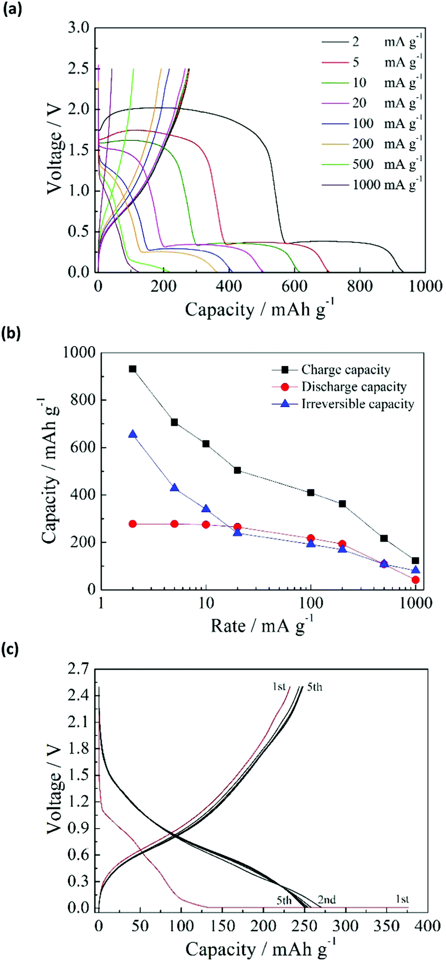 | ||
| Fig. 1 Charge–discharge performance of the TiO2/C electrode: (a) charge–discharge curves in the first cycle at different current rates, (b) relationship between the current rates and capacities in the first cycle, and (c) charge–discharge curves in the CC–CV charge mode and subsequent CC charge–discharge mode. | ||
To investigate the sodiation–desodiation of the TiO2/C electrode, ex situ X-ray diffraction (XRD) analysis was performed for the electrodes in different charge–discharge states. The charge–discharge states at 20 mA g−1 and the XRD results are shown in Fig. 2a and b, respectively. The anatase TiO2 crystal phase gradually disappeared during the charge process (sodiation). Between the as-prepared and 0.5 V-charged electrodes ((1) and (2), respectively), there was no significant change in the XRD pattern except for the peak intensity. A new crystal phase appeared in (3) when the electrode was charged to 0.3 V, although the anatase TiO2 crystal phase was still detectable with weak peak intensity. When the electrode was charged to 0.01 V in (4), the anatase TiO2 crystal phase completely vanished, and only the new crystal phase was detected. The disappearance of the anatase TiO2 crystal phase at the end of charge is in contrast with the result reported by Kim et al.,15 in which the original anatase TiO2 crystal phase was maintained at the end of charge. Meanwhile, the disappearance of the anatase TiO2 crystal phase at the end of charge was reported by Wu et al.,28 although they did not detect any new crystal phase.
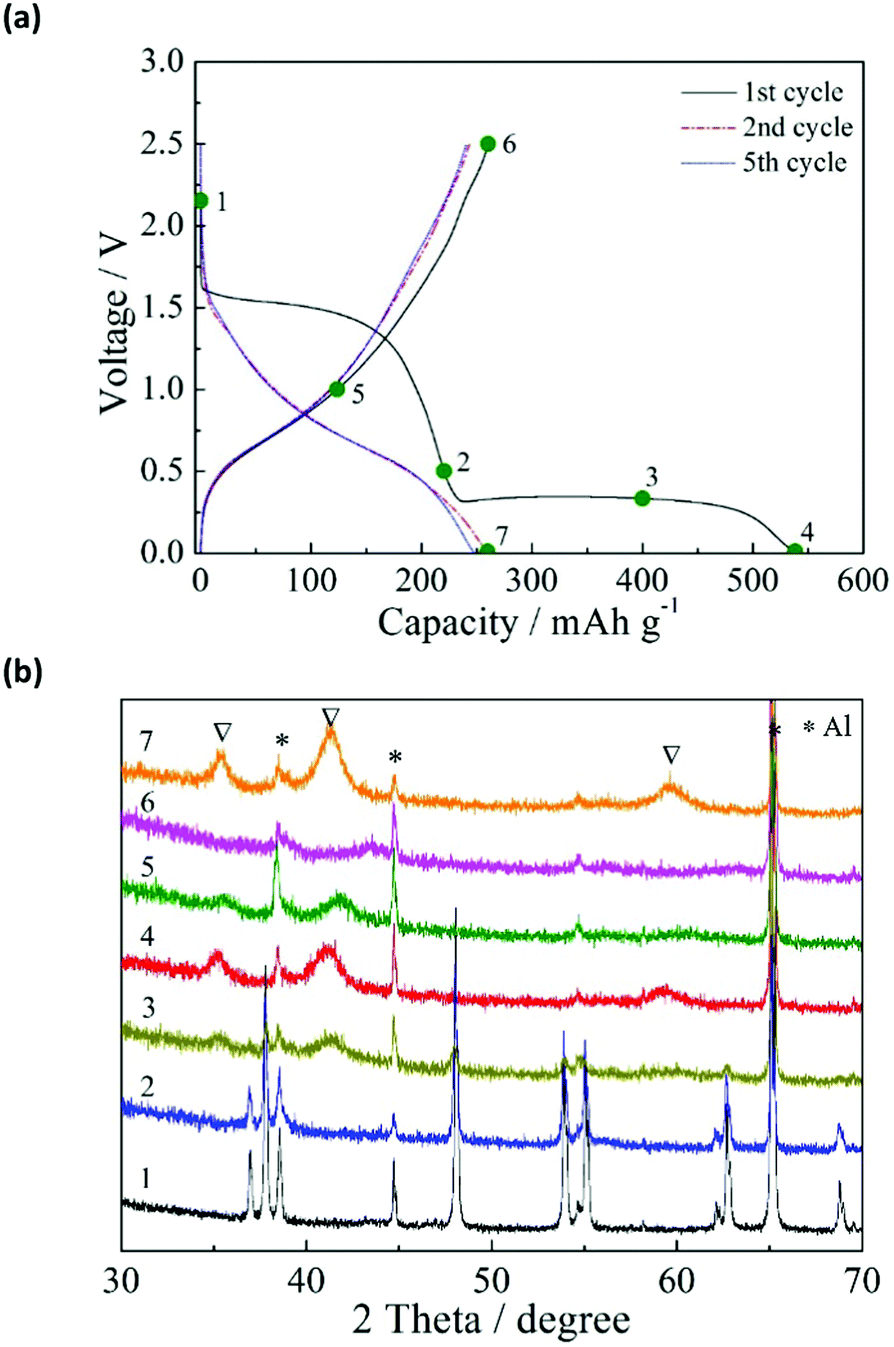 | ||
| Fig. 2 Electrochemical and structural characterization of the TiO2/C electrode: (a) charge–discharge curves of the electrode at 20 mA g−1, during the first (black line), the second (red line), and the fifth (blue line) cycles, and (b) ex situ XRD patterns of the electrodes at various charge/discharge stages: (1) pristine condition, (2) charged to 0.5 V, (3) charged to about 0.3 V, (4) charged to 0.01 V, (5) discharged to 1.0 V, (6) discharged to 2.5 V, and (7) re-charged to 0.01 V, as indicated in (a). The symbols of * and ∇ represent Al substrate and new crystal phase, respectively. | ||
During the discharge process, the Na ion is extracted from the charged TiO2/C electrode (desodiation). For the electrode discharged to 1.0 V (5), the diffraction peaks of the newly formed crystal phase shifted to higher angles and had lower intensities. When the electrode was discharged to 2.5 V (6), the newly formed crystal phase disappeared while there was no re-emergence of the anatase TiO2 crystal phase. When the discharged TiO2/C electrode was re-charged to 0.01 V (7), the new crystal phase appeared again. These results suggest that a new sodium titanate crystal phase was formed during the sodiation process, and that this process was more or less reversible during the charge–discharge cycles. Similar results were also obtained by applying the CC–CV charge mode (ESI,† Fig. S1), where the new crystal phase appeared and disappeared reversibly. Thus, the application of the CC–CV charge mode reduced the first irreversible capacity (due to the side reactions) without changing the sodiation–desodiation mechanism.
To analyze the microscopic morphological changes of the TiO2/C electrode during the charge–discharge process, ex situ scanning electron microscopy (SEM) studies were carried out with the electrode in different charge–discharge states. As shown in Fig. 3a, the pristine electrode consisted of TiO2/C nanoparticles (50–100 nm in size) and graphite particles (dark grey, 1–3 μm). When the electrode was charged to 0.5 V, some round particles were formed on its surface (Fig. 3b). These particles grew in size upon further charging to 0.01 V, reaching about 2 μm in the fully charged state (Fig. 3c). When the CC–CV mode was applied, the formed round particles were much smaller (ca. 0.5 μm) even in the fully charged state (ESI,† Fig. S2). Thus, it is reasonable to regard the round particles as the by-product of the reductive decomposition of electrolyte in the first charge process, and that the CC–CV charge mode can suppress their formation. When the electrode was discharged, the round particles did not disappear, but remained on the surface of the electrode (Fig. 3d and e). They were also present at the same size on the surface of the fully recharged electrode (Fig. 3f). Thus, the round particles were only formed during the first charge.
 | ||
| Fig. 3 SEM images of the TiO2/C electrodes at various charge–discharge stages: (a) pristine electrode, (b) charged to 0.5 V, (c) charged to 0.01 V, (d) discharged to 1.0 V, (e) discharged to 2.5 V, and (f) re-charged to 0.01 V. | ||
The chemical composition of the round particles was investigated with energy dispersive X-ray (EDX) analysis. EDX mapping analysis of the fully charged TiO2/C electrode shows that these particles consisted mostly of Na, F, S and O, and no Ti was detected (ESI,† Fig. S3). EDX point analysis shows that the round particles were possibly composed of NaF, Na2O, and Na2S (ESI,† Fig. S4), which resulted from the electrolyte reduction during the first charge process. These compounds are considered to be in the amorphous phase, since no peaks of crystalline NaF, Na2O, or Na2S were detected in the XRD patterns (Fig. 2b).
Fig. 4a shows the XRD patterns of the TiO2/C electrode discharged to 2.5 V in the first and fifth cycles. The patterns appear identical, each with two main peaks for 200 and 220 with the d-values of 208.8 and 147.4 pm, respectively. These peaks are matched with the cubic TiO phase (JCPDS file No. 00-008-0117), suggesting that the TiO crystal phase was formed in the electrode discharged to 2.5 V. The results from transmission electron microscopy (TEM) and electron diffraction also confirm the formation of the TiO crystal phase in this electrode (Fig. 4b and c). The electron diffraction pattern can be completely indexed to the cubic TiO (rock salt) structure, and the calculated d-values are in agreement with those of the cubic TiO card (ESI,† Table S1). However, EDX analysis shows that Na was also present in the TiO2/C electrode discharged to 2.5 V (Fig. 4d). The amount of Na is estimated to be 0.3 mol per mole of TiO2 in the TiO2/C electrode discharged to 2.5 V (ESI,† Fig. S5 and Table S2). Therefore, we estimate that amorphous titanium oxide and sodium titanate phases were also formed in the TiO2/C electrode discharged to 2.5 V, in addition to the TiO crystal phase.
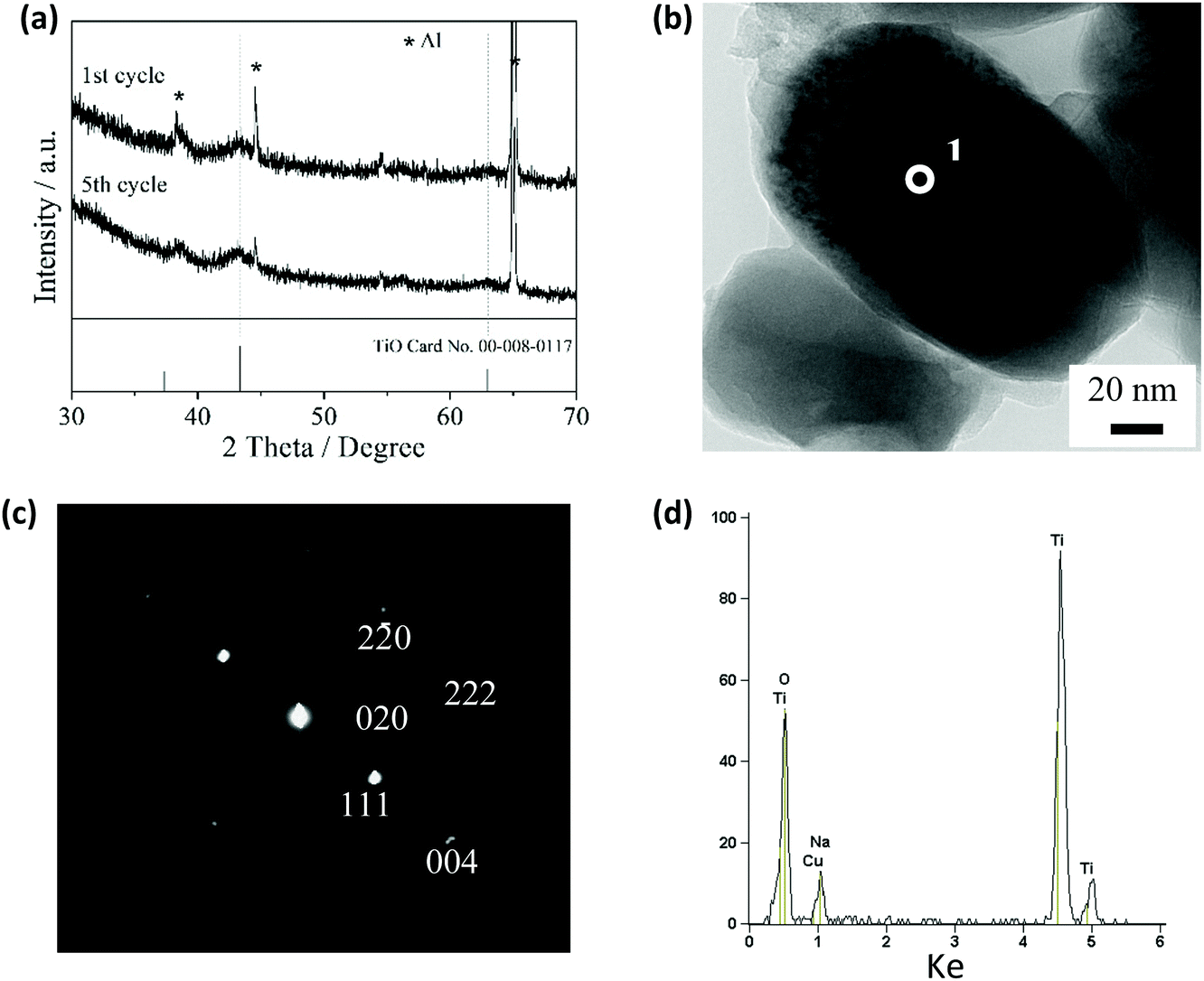 | ||
| Fig. 4 Structural characterization of the TiO2/C electrode discharged to 2.5 V: (a) XRD patterns of the electrodes discharged to 2.5 V in the first and fifth cycles, (b) TEM image of the TiO2/C electrode discharged to 2.5 V, and (c) electron diffraction pattern and (d) EDX spectrum of point 1 in (b). | ||
Fig. 5 shows the XRD patterns of the TiO2/C electrode charged to 0.01 V in the first and fifth cycles. The three main peaks (111, 200, and 220) can be indexed as a face-centred cubic phase with a lattice constant of a = 441 pm. It is worth noting that this cubic phase closely resembles the crystal phases of cubic Na2TiO3 (JCPDS file No. 01-080-6123) and cubic TiO (JCPDS file No. 00-008-0117), and its lattice constant is between those of cubic Na2TiO3 and cubic TiO crystal phases (a = 449 and 418 pm, respectively). Since both Na2TiO3 and TiO have the rock salt structure, they are able to form a solid solution. Therefore, it is reasonable to assume that the formed new cubic crystal phase is a Na2TiIITiIVO4 solid solution. In order to verify this possibility, ball-milled cubic Na2TiO3 and TiO powders were heated at 200–600 °C in an Ar gas flow. Indeed, the XRD analysis of the heated powders indicates the formation of a solid solution below 500 °C (ESI,† Fig. S6), in which the diffraction peaks of the cubic Na2TiO3 phase shifted slightly to a higher angle with the dissolving of the cubic TiO phase. In Fig. S6 (ESI†), some peaks other than cubic Na2TiO3 and cubic TiO are detected at 30–40 degrees at the temperature above 500 °C, which is explained by the phase transition of cubic Na2TiO3 to monoclinic Na2TiO3 at high temperature. Although the heating and electrochemical processes are different in nature, the heating result supports the hypothesis that a solid solution of cubic Na2TiO3 and TiO phases could be formed in the TiO2/C electrode charged to 0.01 V.
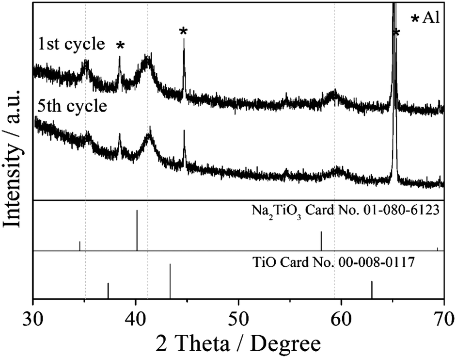 | ||
| Fig. 5 XRD patterns of the TiO2/C electrode charged to 0.01 V in the first and fifth cycles. | ||
During sodiation, TiO2 was fully converted to Na2TiIITiIVO4. One may expect that Na2TiIITiIVO4 should also be fully converted to TiO2 during desodiation. However, the observed discharge capacity (approximately 260 mA h g−1) is lower than that the sodiation capacity at voltages below 0.4 V. Therefore, the desodiation process is incomplete, which is also supported by the EDX analysis (ESI,† Table S2). Part of the Na2TiIITiIVO4 solid solution or its derivatives should be retained in the TiO2/C electrode discharged to 2.5 V. Considering that only the TiO crystal phase was experimentally observed, the desodiation process may result in the formation of amorphous Na2TiO3 and crystalline TiO. In this case, the TiO2/C electrode discharged to 2.5 V should consist of amorphous TiO2, amorphous Na2TiO3, and crystalline TiO phases. This combination of the oxidation states of Ti is different from that described in the literature, where Ti3+ and Ti0 were found in the fully discharged and charged TiO2 electrodes, respectively.28 To further examine the oxidation states of Ti in the electrode charged to 0.01 V and discharged to 2.5 V, X-ray photoelectron spectroscopy (XPS) analysis was performed. As shown in ESI,† Fig. S7, only Ti4+ and Ti2+ were present in these cases, instead of Ti3+ and Ti0. This supports our hypothesis of the formation of Na2TiIITiIVO4 solid solution during the sodiation process, and the mixture of amorphous TiO2, amorphous Na2TiO3, and cubic TiO during desodiation.
To verify that this mixture could act as the active electrode material, an electrode containing a simulated oxide mixture (TiO2/Na2TiO3/TiO with a molar ratio of 8:1:1) was fabricated and electrochemically tested under the same conditions. The simulated oxide mixture was prepared by ball-milling amorphous TiO2 (ca. 10 nm), cubic Na2TiO3 (<100 nm) and cubic TiO (<500 nm) powders to form well-distributed TiO2/Na2TiO3/TiO powders with an average particle size of less than 100 nm. Fig. 6 shows the charge–discharge curves of the simulated oxide mixture electrode at 20 mA g−1. In the first charge process, there was no voltage plateau below 0.4 V, and one plateau was present at about 1.3 V as a result of side reactions due to the nano-sized TiO2 particles. Hence, the sodiation process in the simulated oxide mixture electrode is different from that in the TiO2/C electrode. The first discharge capacity for the simulated oxide mixture electrode is 228 mA h g−1 when scaled for the total mass of active material (TiO2/Na2TiO3/TiO). When the weight of the active material was converted into that of TiO2 based on the molar mass of Ti, the first discharge capacity became 241 mA h g−1, which is close to the value of the TiO2/C electrode (260 mA h g−1 scaled for TiO2/C, Fig. 2a). In contrast, when only amorphous TiO2 was used as the active electrode material, the discharge capacity of the electrode was 112 mA h g−1 (ESI,† Fig. S8), a value much lower than that of the simulated oxide mixture electrode. Moreover, when only Na2TiO3 and TiO were used as the active electrode material, the discharge capacity per active material mass was less than 80 mA h g−1 (ESI,† Fig. S9). Considering these data, the combination of crystalline Na2TiO3 and TiO in the amorphous TiO2 phase obviously improved the electrochemical sodiation–desodiation properties. Therefore, in addition to the confirmed cubic TiO phase, the speculated formation of amorphous TiO2 and Na2TiO3 phases in the electrode discharged to 2.5 V is quite reasonable.
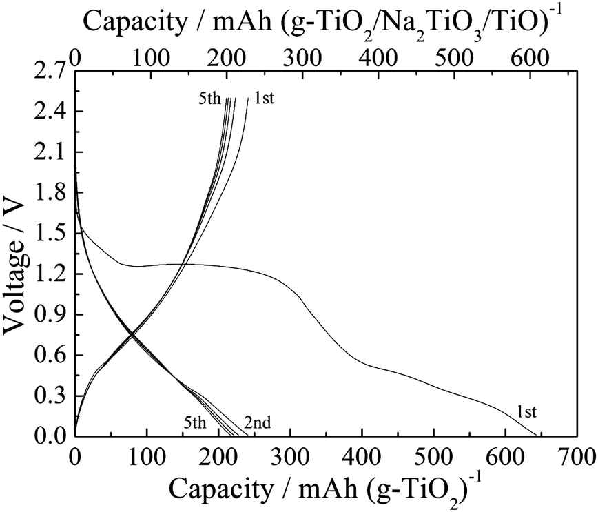 | ||
| Fig. 6 Charge–discharge curves of the electrode with simulated oxide mixture (TiO2/Na2TiO3/TiO) at 20 mA g−1. | ||
According to the above analysis, the newly proposed sodiation and desodiation mechanism of anatase TiO2/C electrode is as follows:
(1) First charge process:
| 2TiO2 + 2Na+ + 2e− → Na2TiIITiIVO4 |
(2) First discharge process:
| 5Na2TiIITiIVO4 → 8TiO2 + Na2TiO3 + TiO + 8Na+ + 8e− |
(3) Reversible reaction processes:
| 8TiO2 + Na2TiO3 + TiO + 8Na+ + 8e− ⇄ 5Na2TiIITiIVO4 |
In the first charge process, Na ions react with anatase TiO2 to form a cubic Na2TiIITiIVO4 solid solution, accompanied by some side reactions such as electrolyte reduction. In the following first discharge, the Na2TiIITiIVO4 solid solution is converted into a mixture of amorphous TiO2, amorphous Na2TiO3 and cubic TiO. In the subsequent cycles, the mixture reversibly reacts with Na ions as the active electrode material, causing the formation and dissolution of the Na2TiIITiIVO4 solid solution.
Conclusions
In summary, we investigated the sodiation and desodiation of an anatase TiO2/C negative electrode in an ionic liquid electrolyte at 90 °C, and revealed a new sodiation–desodiation mechanism. A Na2TiIITiIVO4 solid solution was formed in the first sodiation process. During the desodiation process, the solid solution was converted reversibly into amorphous TiO2, amorphous Na2TiO3, and crystalline TiO, thereby providing a high reversible specific capacity of ca. 260 mA h g−1. The new active material, i.e., the composite of TiO2, Na2TiO3 and TiO, could provide key information for the design of new negative electrode materials based on anatase TiO2. We believe that the results shown here will give powerful insights for creating safer rechargeable sodium batteries with higher energy density.Acknowledgements
This study was partly supported by the Advanced Low Carbon Technology Research and Development Program (ALCA, No. 3428) of the Japan Science and Technology Agency (JST) and the “Elements Strategy Initiative to Form Core Research Center” program of the Japanese Ministry of Education, Culture, Sports, Science and Technology (MEXT).Notes and references
- N. Yabuuchi, M. Kajiyama, J. Iwatate, H. Nishikawa, S. Hitomi, R. Okuyama, R. Usui, Y. Yamada and S. Komaba, Nat. Mater., 2012, 11, 512–517 CrossRef CAS PubMed.
- E. Hosono, T. Saito, J. Hoshino, M. Okubo, Y. Saito, D. Nishio-Hamane, T. Kudo and H. S. Zhou, J. Power Sources, 2012, 217, 43–46 CrossRef CAS.
- J. Billaud, R. J. Clement, A. R. Armstrong, J. Canales-Vazquez, P. Rozier, C. P. Grey and P. G. Bruce, J. Am. Chem. Soc., 2014, 136, 17243–17248 CrossRef CAS PubMed.
- C. Y. Yu, J. S. Park, H. G. Jung, K. Y. Chung, D. Aurbach, Y. K. Sun and S. T. Myung, Energy Environ. Sci., 2015, 8, 2019–2026 CAS.
- P. Barpanda, G. D. Liu, C. D. Ling, M. Tamaru, M. Avdeev, S. C. Chung, Y. Yamada and A. Yamada, Chem. Mater., 2013, 25, 3480–3487 CrossRef CAS.
- Z. L. Jian, L. Zhao, H. L. Pan, Y. S. Hu, H. Li, W. Chen and L. Q. Chen, Electrochem. Commun., 2012, 14, 86–89 CrossRef CAS.
- J. Kim, D. H. Seo, H. Kim, I. Park, J. K. Yoo, S. K. Jung, Y. U. Park, W. A. Goddard and K. Kang, Energy Environ. Sci., 2015, 8, 540–545 CAS.
- L. Wu, X. H. Hu, J. F. Qian, F. Pei, F. Y. Wu, R. J. Mao, X. P. Ai, H. X. Yang and Y. L. Cao, Energy Environ. Sci., 2014, 7, 323–328 CAS.
- J. W. Wang, X. H. Liu, S. X. Mao and J. Y. Huang, Nano Lett., 2012, 12, 5897–5902 CrossRef CAS PubMed.
- S. Komaba, W. Murata, T. Ishikawa, N. Yabuuchi, T. Ozeki, T. Nakayama, A. Ogata, K. Gotoh and K. Fujiwara, Adv. Funct. Mater., 2011, 21, 3859–3867 CrossRef CAS.
- H. Pan, X. Lu, X. Yu, Y.-S. Hu, H. Li, X.-Q. Yang and L. Chen, Adv. Energy Mater., 2013, 3, 1186–1194 CrossRef CAS.
- M. Shirpour, J. Cabana and M. Doeff, Energy Environ. Sci., 2013, 6, 2538–2547 CAS.
- H. Xiong, M. D. Slater, M. Balasubramanian, C. S. Johnson and T. Rajh, J. Phys. Chem. Lett., 2011, 2, 2560–2565 CrossRef CAS.
- Y. Xu, E. M. Lotfabad, H. Wang, B. Farbod, Z. Xu, A. Kohandehghan and D. Mitlin, Chem. Commun., 2013, 49, 8973–8975 RSC.
- K. T. Kim, G. Ali, K. Y. Chung, C. S. Yoon, H. Yashiro, Y. K. Sun, J. Lu, K. Amine and S. T. Myung, Nano Lett., 2014, 14, 416–422 CrossRef CAS PubMed.
- L. Wu, D. Buchholz, D. Bresser, L. Gomes Chagas and S. Passerini, J. Power Sources, 2014, 251, 379–385 CrossRef CAS.
- X. M. Yang, C. Wang, Y. C. Yang, Y. Zhang, X. N. Jia, J. Chen and X. B. Ji, J. Mater. Chem. A, 2015, 3, 8800–8807 CAS.
- J. P. Huang, D. D. Yuan, H. Z. Zhang, Y. L. Cao, G. R. Li, H. X. Yang and X. P. Gao, RSC Adv., 2013, 3, 12593 RSC.
- J. C. Perez-Flores, C. Baehtz, A. Kuhn and F. Garcia-Alvarado, J. Mater. Chem. A, 2014, 2, 1825–1833 CAS.
- H. Usui, S. Yoshioka, K. Wasada, M. Shimizu and H. Sakaguchi, ACS Appl. Mater. Interfaces, 2015, 7, 6567–6573 CAS.
- C. S. Ding, T. Nohira and R. Hagiwara, J. Mater. Chem. A, 2015, 3, 20767–20771 CAS.
- G. Sudant, E. Baudrin, D. Larcher and J. M. Tarascon, J. Mater. Chem., 2005, 15, 1263–1269 CAS.
- R. van de Krol, A. Goossens and E. A. Meulenkamp, J. Electrochem. Soc., 1999, 146, 3150–3154 CrossRef CAS.
- R. J. Cava, D. W. Murphy, S. Zahurak, A. Santoro and R. S. Roth, J. Solid State Chem., 1984, 53, 64–75 CrossRef CAS.
- M. Wagemaker, W. J. H. Borghols and F. M. Mulder, J. Am. Chem. Soc., 2007, 129, 4323–4327 CrossRef CAS PubMed.
- M. Wagemaker, G. J. Kearley, A. A. van Well, H. Mutka and F. M. Mulder, J. Am. Chem. Soc., 2003, 125, 840–848 CrossRef CAS PubMed.
- A. A. Belak, Y. Z. Wang and A. Van der Ven, Chem. Mater., 2012, 24, 2894–2898 CrossRef CAS.
- L. M. Wu, D. Bresser, D. Buchholz, G. A. Giffin, C. R. Castro, A. Ochel and S. Passerini, Adv. Energy Mater., 2015, 5, 1401142 CrossRef.
Footnote |
| † Electronic supplementary information (ESI) available. See DOI: 10.1039/c6cp05944a |
| This journal is © the Owner Societies 2016 |