Energy frameworks and a topological analysis of the supramolecular features in in situ cryocrystallized liquids: tuning the weak interaction landscape via fluorination†
Received
26th August 2016
, Accepted 31st October 2016
First published on 31st October 2016
Abstract
Weak intermolecular interactions observed in crystalline materials are often influenced or forced by stronger interactions such as classical hydrogen bonds. Room temperature liquids offer a scenario where such strong interactions are absent so that the role and nature of the weak interactions can be studied more reliably. In this context, we have analyzed the common organic reagent benzoyl chloride (BC) and a series of its fluorinated derivatives using in situ cryocrystallography. The intermolecular interaction energies have been estimated and their topologies explored using energy framework analysis in a series of ten benzoyl chloride analogues, which reveal that the π⋯π stacking interactions serve as the primary building blocks in these crystal structures. The crystal packing is also stabilized by a variety of interaction motifs involving weak C–H⋯O/F/Cl hydrogen bonds and F⋯F, F⋯Cl, and Cl⋯Cl interactions. It is found that fluorination alters the electrostatic nature of the benzoyl chlorides, with subsequent changes in the formation of different weak interaction motifs. The effects of fluorination on these weak intermolecular interactions have been systematically analyzed further via detailed inputs from a topological analysis of the electron density and Hirshfeld surface analysis.
Introduction
Intermolecular interactions lie at the heart of the understanding of the events that govern molecular recognition. In this regard, the role of strong H-bonds1 and π⋯π stacking interactions,2 albeit weak, has been well established. Furthermore, in recent years halogens, in particular organic fluorine, have been observed to play a significant role in supramolecular assemblies, and their significance in the context of crystal engineering is now well recognized.3–6 Fluorine-containing organic molecules cause major changes in the physicochemical properties, chemical reactivity, and biological activity compared to the non-fluorinated analogues.7–14 Fluorination is a widely applied technique to amplify the chemical reactivity with minor alterations in the molecular size/shape/structure of the different molecules, such as drugs and functional materials. It is now well recognized that the fluorine atom generates different types of packing motifs which assemble the molecules in a crystal lattice via C–F⋯H, C–F⋯F and C–F⋯π intermolecular interactions in the absence of strong hydrogen bond donors (N–H and O–H).15,16 With the increase in the number of fluorine atoms, F⋯F contacts also increase wherein the other interactions like C–H⋯F and C–H⋯O decrease in the crystal packing.15 For highly fluorinated compounds (like pentafluoropyridine, 2,3,6-trifluoropyridine, fluorinated benzophenones and fluorinated N-phenyl maleimides) there always exists a competition between the formation of F⋯F contacts and the other intermolecular interactions.15–18 Recently, Desiraju et al. have shown that chemical substitution using fluorine could be an effective method to scan the complex crystal structural landscape to obtain otherwise unattainable structural analogues of crystal structures.19
For mono-fluorinated compounds, the fluorine atom prefers to form C–H⋯F interactions rather than the F⋯F contact. But the heavier halogen (Cl, Br and I) atoms show zig-zag halogen⋯halogen (Cl⋯Cl, Br⋯Br and I⋯I) interactions in the crystal packing.20 Intermolecular hetero halogen⋯halogen interaction, for example, the F⋯Cl contact, shows the “halogen bond donor” character for the organic fluorine atom, which has been established via experimental charge density analysis.21 The nature of the Cl⋯Cl interaction22,23 has been investigated in detail by Desiraju24 and Price.25 Desiraju has shown that short intermolecular Cl⋯Cl contacts occur very frequently in chloro aromatic compounds. Using different challenging techniques (zone-melting and in situ) the crystallization and the determination of the 3D molecular structure of compounds which are not easy to crystallize are of extreme interest in crystal engineering.26–29In situ cryocrystallization is a technique that is used to determine the molecular structure of the liquid crystallized on the diffractometer in a capillary using an infrared laser.30–32 This method can be made applicable not only for liquids21,33–35 but also for compounds which are low melting solids,36,37 ionic liquids,38,39 gas mixtures,40 gaseous hydrates,41 liquid–gas mixtures42 and for the generation of alloy phases at low temperatures.43
The nucleation and crystal growth of organic compounds from solution is still an enigmatic phenomenon. Many kinetic and thermodynamic factors and solute–solvent interactions influence the nucleation process42–46 and make it more complicated. In this regard, in situ cryocrystallization offers a great opportunity to study and understand the structural behavior of room-temperature organic liquids. Solidification of room temperature liquids under non-ambient conditions (e.g. low temperature) often results in glass formation.47 It is because of the lower entropy difference between the solid and liquid states upon cooling near the melting temperature. Viscosity also leads to reduced nucleation and affects the crystallization process.48,49 In addition to this fundamental barrier for nucleation at a very low temperature, fluorinated organic compounds often suffer from orientation fixation and disorder because of high mobility in crystal nuclei and weak intermolecular interactions which dominate the crystal packing along with strong interactions.50 So, it is very important to set up favorable conditions for which suitable single crystals can be grown and this is the grand challenge of in situ cryocrystallization of fluorine-containing organic compounds. The in situ crystallization procedure demands no solvent and no hazardous processing materials. In this regard, it can be considered as a “green technology”.29
In this work, using in situ cryocrystallography we analyze the weak interactions in a series of fluorinated benzoyl chloride analogues which are room-temperature liquids. This allows us to examine the role of weak interaction motifs involving C–H⋯O/F/Cl hydrogen bonds and F⋯F, F⋯Cl, and Cl⋯Cl interactions involving the utilization of the different donor and acceptor atoms. It is extremely difficult to a priori predict the presence of different intermolecular interactions in liquids wherein the chaotic thermal motion plays a significant role. Hence, in situ cryocrystallography of liquids can be a useful technique to study the arrangement of molecules in such systems. Here we have presented an in-depth analysis of such interaction motifs and their variation with fluorination in a series of ten benzoyl chloride derivatives using energy framework analysis (intermolecular interaction topologies) and PIXEL calculations along with a topological analysis (QTAIM) of the electron density which provide physical insights into the nature and energetics associated with these interactions.
Results and discussion
Scheme 1 shows the fluoro derivatives (monofluoro, difluoro and trifluoro) of benzoyl chloride (parent structure) obtained by varying the position of the fluorine atoms on the phenyl ring. To study the variation in molecular arrangements as well as the role of weak intermolecular interactions, we have used an in situ cryocrystallization technique for 3FBC, 35DFBC and 345TFBC. The crystallization conditions for these three liquids are provided in the ESI,† (Table S1). Fig. 1 depicts the crystal images inside the Lindemann glass capillary (2 cm long and 0.3 mm in diameter) taken at the corresponding temperatures. 35DFBC and 345TFBC have been crystallized via an OHCD (optical heating and crystallization device) using a CO2 laser, and the data were collected with only ω scans. The details of the in situ cryocrystallization procedure are available in the ESI† of the previous report.51
 |
| | Scheme 1 Benzoyl chloride and its fluorinated analogues. | |
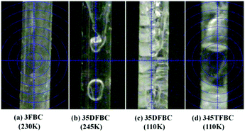 |
| | Fig. 1 Crystal images of 3FBC, 35DFBC and 345TFBC at different temperatures. | |
The compound 3FBC was crystallized in the absence of (OHCD), i.e., the obtained polycrystalline solid was annealed by shifting the nitrogen stream along the length of the Lindemann capillary several times, as shown in Fig. S1 (ESI†). In this case, the diffraction data were collected with ω scan and ϕ scan. The still images (Fig. S2, ESI†) show the quality of the diffraction pattern for these three in situ cryocrystallized liquids. Table S2 (ESI†) represents the data collection and the crystal structure refinement parameters. Fig. S3 (ESI†) shows the ORTEP for these liquids (3FBC, 35DFBC and 345TFBC) with the corresponding atom numbering. For the sake of comparison, the energetics of 4FBC20 and 23DFBC20,51 were also taken into account along with this current study. In our previous report,51 we have described only the molecular conformation of BC, 2FBC, 23DFBC, 24DFBC, 25DFBC and 26DFBC stabilized by the presence of “only” intramolecular interactions of the type C–H⋯Cl–C, C–F⋯O![[double bond, length as m-dash]](https://www.rsc.org/images/entities/char_e001.gif) C and C–F⋯Cl–C. In the current study, we have discussed the role of weak intermolecular interactions that play a crucial role towards the stabilization of the overall crystal packing, in the absence of any strong interaction via the analysis of the energy frameworks. These molecules have a strong (oxygen atom of the –COCl group) as well as a weak (–F, –Cl) acceptor and also the aromatic C–H bonds which act as a donor with differential acidity depending on the presence of electron withdrawing groups in the vicinity.
C and C–F⋯Cl–C. In the current study, we have discussed the role of weak intermolecular interactions that play a crucial role towards the stabilization of the overall crystal packing, in the absence of any strong interaction via the analysis of the energy frameworks. These molecules have a strong (oxygen atom of the –COCl group) as well as a weak (–F, –Cl) acceptor and also the aromatic C–H bonds which act as a donor with differential acidity depending on the presence of electron withdrawing groups in the vicinity.
The packing networks of all fluorinated benzoyl chlorides are shown in Fig. S4–S11 (ESI†). Table S3 (ESI†) lists all the molecular pairs extracted from the crystal packing. The stabilization energy between the two molecules was obtained from the PIXEL52–55 method. In the case of BC, two successive molecular sheets (associated with bifurcated C–H⋯Cl interactions), aligned with each other at an angle of 58.6° and connected via bifurcated C–H⋯O interactions, (Fig. S4, ESI†) are present. The participation of the fluorine atom changes the crystal packing. In the case of 2FBC, there is a formation of a Cl⋯Cl [d = 3.523(2) Å] zig-zag molecular chain (Fig. S5a, ESI†) along the c-axis, which connects the molecular pairs (I) stacked on each other via π⋯π interaction [d = 3.820(2) Å]. Down the ab plane, the molecules were packed in a cyclic way along the c-axis leading to the formation of a molecular sheet (Fig. S5b, ESI†) involving the molecular pairs I (involving C–H⋯Cl and C–H⋯O interactions), II (involving C–H⋯F and C–H⋯O interactions), IV (involving C–H⋯F) and V (Cl⋯Cl contact), which provide the maximum stabilization to the crystal lattice whereas in the case of 3FBC (Fig. S3a, ESI†), the molecules were found to form the molecular sheet involving the molecular chains (Fig. S6a, ESI†) associated with a very short Type I F⋯F contact [d = 2.664(10) Å] and intermolecular F⋯O contact [2.957(7) Å, −2.3 kcal mol−1] and a weak C–H⋯O interaction. There is a formation of a cyclic ring associated with six molecules involving four F⋯O contacts and two F⋯F contacts (Fig. S6b, ESI†). Furthermore, the molecular chains finally generate a 2D molecular sheet where each molecular chain (highlighted with transparent sky blue color) intersects the other molecular chain at an angle of 66° (Fig. S6b, ESI†). These molecular sheets stack on top of each other via π⋯π stacking [d = 3.828(1) Å]. The supramolecular construct of BC, 2FBC, 3FBC, 24DFBC, 26DFBC and 345TFBC depicts the mechanism via which the molecules self-assemble leading to the formation of a zig-zag molecular sheet (Fig. 2). This provides physical insights into the plausible molecular origin of pre-nucleation aggregates that lead to the formation of the final crystal in these molecules. The molecular arrangements in 2FBC are similar to the parent compound (BC) (Fig. 2) whereas 3FBC, 24DFBC (Fig. S8, ESI†), and 26DFBC (Fig. S10a and b, ESI†) form similar types of zig-zag layers, where the blue arrows indicate the alternate parallel column associated with π⋯π stacking. But 345TFBC (Fig. S3c, ESI†) forms a different type of zig-zag molecular sheet. Down the ac plane, four (two molecules of 345TFBC-1 and two molecules of 345TFBC-2) molecules form two types of the centrosymmetric tetramers (Fig. S11a, ESI†). One tetramer is formed utilizing the molecular pairs IV (associated with intermolecular Cl⋯Cl and C–H⋯O interactions), V (involving C–H⋯O and F⋯O contacts) and XII (Cl⋯Cl). The other tetramer was generated via the molecular pairs IV, IX [involving short and highly directional intermolecular C–H⋯F interactions (dH⋯F = 2.38 Å and ∠C–H⋯F = 174°)] and XIII (asymmetric unit wherein two symmetry independent molecules interact with each other via bifurcated F⋯F interactions). Finally, these two tetramers together generate a molecular sheet down the ac plane (Fig. S11a, ESI†). Such types of molecular sheets form a zigzag array wherein the sheets were stacked on each other via the molecular pairs II, III and VII (Fig. S11b and Table S3, ESI†).
 |
| | Fig. 2 The formation of zig-zag molecular sheets by weak C–H⋯O/F/Cl interactions, stacked on each other (arrows indicate the direction of π⋯π stacking column). | |
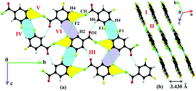
There are some common features in the crystal packing which have been observed. The molecules of 4FBC (Fig. 3), 23DFBC (Fig. S7, ESI†), 25DFBC (Fig. S9, ESI†) and 35DFBC (Fig. 4) generate planar molecular sheets (involving C–H⋯O/F/Cl and halogen⋯halogen interactions) which were stacked parallel to each other via π⋯π stacking with the perpendicular inter-layer distance of 3.1–3.4 Å (Fig. 5). 4FBC has two polymorphic forms namely I and II (metastable polytypic form) crystallized via varying the rate of nucleation during the in situ cryocrystallization. The difference between these two polymorphic forms is in the molecular stacking, i.e., the two –COCl groups are in opposite directions in Form II whereas they are at an angle of 120° in Form I. Intermolecular Cl⋯F and F⋯O contacts also provide significant stabilization towards the crystal packing in some cases. It is noteworthy that the intermolecular Cl⋯Cl interaction is absent in the crystal packing of 3FBC, 4FBC, 23DFBC and 35DFBC, which was present in other fluorinated benzoyl chlorides, including the parent compound BC. The chlorine atom of the –COCl group forms the intermolecular Cl⋯F contact, rather than the Cl⋯Cl interaction in the case of 4FBC, 23DFBC and 35DFBC. But 25DFBC and 26DFBC contain both the interactions (Cl⋯Cl and Cl⋯F) together in the solid state.
 |
| | Fig. 3 Crystal packing of 4FBC-I: (a) formation of a molecular sheet associated with weak C–H⋯O, C–H⋯F, C–H⋯Cl and Cl⋯F intermolecular interactions down the (−101) plane and (b) stacking of the consecutive molecular sheets along the c-axis. | |
 |
| | Fig. 4 Packing view of 35DFBC: (a) formation of a molecular sheet associated with R22(8) C–H⋯F dimers, Cl⋯F contacts and C–H⋯Cl interactions down the bc plane and (b) stacking of molecular sheets via π⋯π interaction down the (101) plane. | |
 |
| | Fig. 5 General molecular arrangement patterns in fluorinated benzoyl chlorides; the formation of planar molecular sheets by weak C–H⋯O/F/Cl interactions (black dotted lines) and packing of these sheets by π⋯π stacking (orange lines). | |
The formation of molecular sheets via different intermolecular interactions depends on the approach of the molecules with the neighboring molecules. This feature is “extremely sensitive” to the electronic environment and the final supramolecular arrangement is a very delicate balance of “attractive” and “repulsion” forces which allow for a particular orientation of molecules in the crystal. In the case of 4FBC, one molecule approaches the other molecule, related via the 21 screw axis, leading to the formation of intermolecular Cl⋯F contacts as well as bifurcated C–H⋯O and C–H⋯F (fluorine and oxygen atoms act as bifurcated acceptors) interactions in the same plane, overall leading to the formation of planar molecular sheets (Fig. 6a). All these interactions are also preserved in 23DFBC (the oxygen atom acting as a bifurcated acceptor and the aromatic hydrogen atom acts as a bifurcated donor) wherein the molecule approaches towards the neighboring molecule with the similar molecular orientation (via the translation along the a direction) (Fig. 6b) during the process of nucleation. If the molecules want to follow the similar pattern as in 4FBC, then two fluorine atoms will come very close to the carbonyl oxygen atom, which is not favorable. So, this is on account of the reduction in repulsion, which includes formation of favorable supramolecular arrangements in 23DFBC. In the case of 35DFBC (Fig. 4 and 6c), there is a formation of C–H⋯F dimer and C–H⋯O interaction instead of bifurcated C–H⋯O as well as bifurcated C–H⋯F, but the intermolecular Cl⋯F contact is still preserved. In 25DFBC (Fig. 6d and Fig. S9, ESI†) the symmetry independent molecules present in the asymmetric unit translate along the [111] direction of the molecular sheet and form C–H⋯O chains along the b direction.
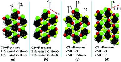 |
| | Fig. 6 The orientation of the molecules in the planar molecular sheets of (a) 4FBC, (b) 23DFBC, (c) 35DFBC and (d) 25DFBC. | |
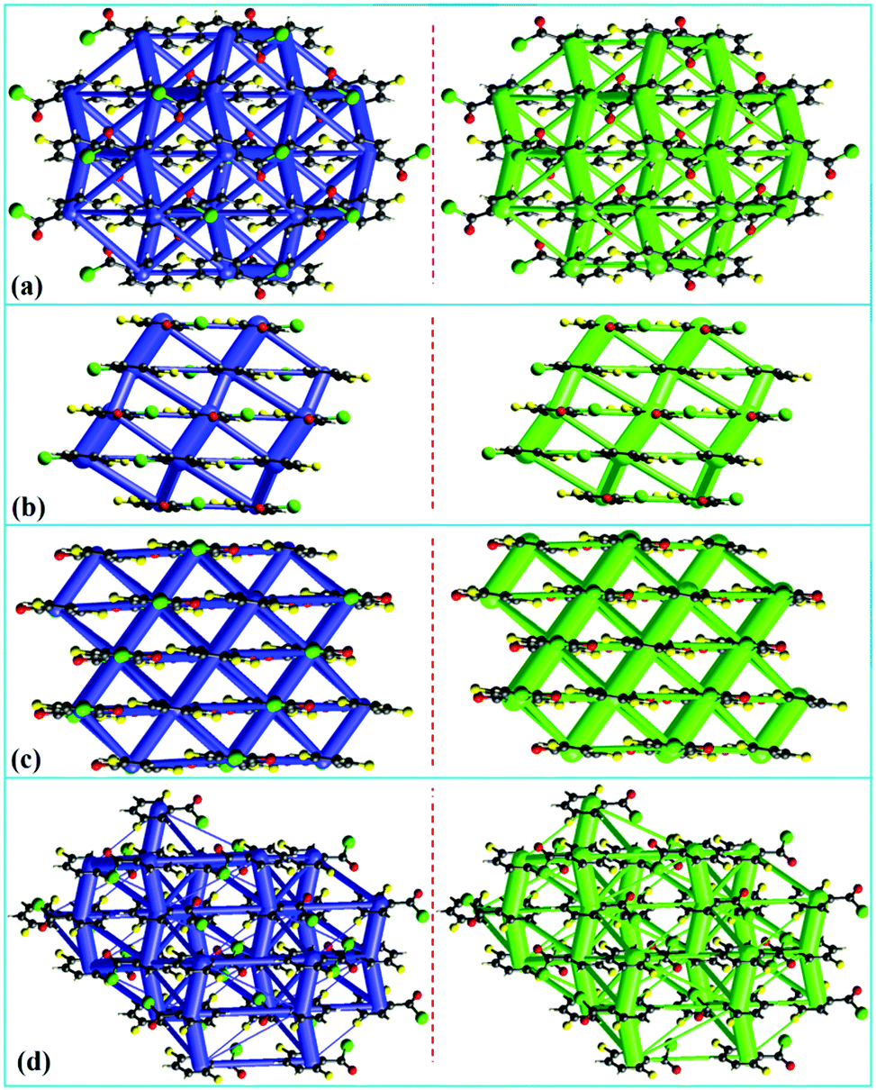
It is observed that π⋯π stacking interaction dominates the crystal packing in these compounds, in the absence of any strong hydrogen bond donors. These crystal structures may be visualized as molecular columns formed by π⋯π stacking, and these columns are further bound to each other by weak non-covalent interactions involving F and Cl atoms as well as weak C–H⋯O/F/Cl hydrogen bonded motifs. In order to visualize the interaction topology in these crystal structures, energy framework analysis has been performed using CrystalExplorer.56 In this method, the values of interaction energies are used to construct the three-dimensional topology of interactions that are termed as energy frameworks.57 The pairwise intermolecular interaction energies in the crystal structures are represented as cylinders joining the molecules. The radii of these cylinders are set proportional to the strength of the intermolecular interaction. Recently, we have applied the energy framework analysis to various contexts of crystal engineering such as in the analysis of mechanical properties of crystals,57 and in the analysis of supramolecular recognition units,58 isostructurality and quasi-isostructural polymorphism.59 An in-depth analysis of the 3D-topologies for the predominant intermolecular interactions in the crystal structures of ten benzoyl chlorides established the “significant contribution” of π⋯π stacking. This feature highlights the fact that amplification of the number of short contacts, between the atoms in the “interlayer” molecular sheets, is the structure guiding interaction. The molecular columns formed by π⋯π stacking serve as the pillars in these crystal structures (shown as the thickest tubes in Fig. 7 and 8). It is also noteworthy that the atoms participating in interactions in the “intra-layer” sheet are also of significance in molecular packing. Energy frameworks of all the 10 crystal structures discussed in this study and those corresponding to the electrostatic and dispersion components are given in the ESI,† (Fig. S12–S14). Not surprisingly, it is the dispersion contribution that dominates the intermolecular interactions. Fig. 7 shows the energy frameworks (net interaction energy and the dispersion component) for the corresponding parallel molecular sheets. It is observed that the energy distribution (electrostatic and dispersion) patterns of 4FBC and 35DFBC are similar. These give the zigzag tubes intersecting the molecular sheets along the a- and c-axes for 4FBC and 35DFBC, respectively. Similarly, the energy distribution patterns of 23DFBC and 25DFBC are also comparable. Here, two different types of π⋯π stacking with different energies give a parallel cylindrical tube with a larger diameter (compared to 4FBC and 35DFBC) for the total energy and dispersion term. The energy frameworks for the other fluorinated analogues wherein the zig-zag molecular sheets are formed are shown in Fig. 8. The net interaction energy and the dispersion term for BC, 2FBC, 3FBC and 24DFBC show the parallel cylindrical tubes along which the π⋯π stacking occurs. The energy distribution patterns for 26DFBC and 345TFBC are different from the other eight-fluorinated benzoyl chlorides.
 |
| | Fig. 7 Energy frameworks for fluorine substituted benzoyl chlorides: (a) 4FBC, (b) 23DFBC, (c) 25DFBC and (d) 35DFBC, representing the net interaction energy (in blue color) and the dispersion term (green color). | |
 |
| | Fig. 8 Energy frameworks for (a) BC, (b) 2FBC, (c) 24DFBC and (d) 345TFBC, representing the net interaction energy (in blue color) and the dispersion term (green color). | |
Variation in π⋯π stacking with fluorine substitution
It is found that the strength of π⋯π stacking interaction in this series of benzoyl chlorides depends mainly on two factors: (i) orientation of the molecules with respect to each other (anti-parallel orientation results in stronger interaction, as it is electrostatically favorable), and (ii) the degree of effective overlap of the phenyl rings (as reflected in the Cg⋯Cg distances).
The following order is observed for π⋯π stacking molecular dimers (given in kcal mol−1, and the parallel and anti-parallel molecular orientations are represented by the symbols ↑↑ and ↓↑): these energy values are derived from the energy framework module of CrystalExplorer for an accurate description of dispersion contribution to the π⋯π stacking.
| BC (−3.7, ↑↑) < 2FBC (−3.3, ↑↑) ∼ 3FBC (−3.6, ↑↑) ∼ 345TFBC (−2.3, ↑↑) < 24DFBC (−3.8, ↑↑) < 4FBC (−3.7, ↓↑) ∼ 35DFBC (−3.8, ↑↑) < 25DFBC (−4.9/−4.8, ↓↑) ∼ 26DFBC (−3.2/−5.6, ↓↑) < 23DFBC (−5.3/−3.8, ↓↑) |
As a general trend it is observed that π⋯π stacking interaction becomes stronger with the increase in number of fluorine substitution. A notable anomaly from this trend is exhibited by the trifluoro-substituted analogue 345TFBC, where the lower value of interaction energy can be rationalized based on the offset positions of the phenyl rings involved in the π⋯π stacking (leading to a less effective π⋯π overlap) and the anti-parallel molecular orientation. Interestingly, a nearly equi-energetic molecular dimer is found in 345TFBC, formed by the Burgi–Dunitz type of OC⋯OC interaction (−4.1 kcal mol−1). Notably, certain molecular dimers with relatively high interaction strengths (−2 to −5 kcal mol−1), which are not characterized by any hydrogen bonds or halogen interactions, are found in BC, 3FBC, 4FBC, 23DFBC, and 26DFBC. These are stabilized by the dipole interactions such as OC⋯CO/C–F⋯C–F or by sheer anti-parallel molecular orientation. A detailed analysis of interaction motifs formed by weak C–H⋯O/F/Cl hydrogen bonds and halogen interactions is given in the later sections.
Variation in lattice energies
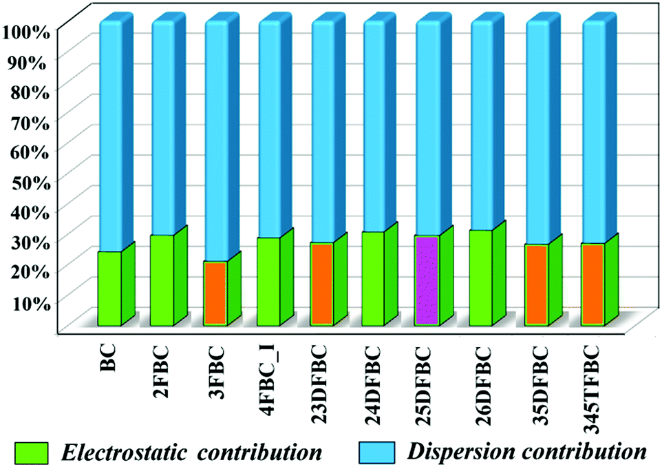
The programs PIXEL and CrystalExplorer provide the information about the intermolecular interaction energy with their corresponding partitioned energies, but only PIXEL gives the total lattice energy of the crystal. The lattice energies of BC and fluorinated BCs are partitioned into the Coulombic, polarization, dispersion and repulsion terms as shown in Table 1. The energies are in the range of −14.5 to −17.2 kcal mol−1. In Fig. 9, the percentages of electrostatic and dispersion contributions in the total stabilization for all the crystals are shown. The addition of the fluorine atom in the phenyl ring of 2FBC (lattice energy is −17.2 kcal mol−1; electrostatic contribution is 30%) decreases the lattice energy for 23DFBC (−15.9 kcal mol−1; electrostatic contribution is 27.3%) and 25DFBC (−16.6 kcal mol−1; 29.6% electrostatic contribution). However, the lattice energy remains the same for 24DFBC (−17.2 kcal mol−1; 30.7% electrostatic contribution). The energy framework analysis also shows the weak contribution from the electrostatic terms (red color) [Fig. S12–S14, ESI†] and the dominance of the dispersion term (green color). It has been observed that the meta-fluorinated analogues have reduced lattice energies than the ortho/para substituted BCs. The participation and the greater contribution of weak intermolecular F⋯F and F⋯O contacts in the crystal packing may lead to reduced electrostatic contribution [3FBC (−14.5 kcal mol−1; 21.1%), 23DFBC, 35DFBC (−15.1 kcal mol−1; 26.74%) and 345TFBC (−14.6 kcal mol−1; 27%)] towards the overall stabilization in the case of meta analogues.
Table 1 Lattice energies (obtained from PIXEL) of the fluorinated benzoyl chlorides (in kcal mol−1)
| Code |
E
Coul
|
E
Pol
|
E
Disp
|
E
Rep
|
E
Tot
|
|
BC
|
−4.7 |
−1.5 |
−19.4 |
9.6 |
−16.0 |
|
2FBC
|
−6.2 |
−2.6 |
−20.9 |
13.1 |
−17.2 |
|
3FBC
|
−3.5 |
−1.5 |
−18.7 |
9.3 |
−14.5 |
|
4FBC
|
−6.4 |
−2.0 |
−20.8 |
12.8 |
−16.5 |
|
23DFBC
|
−5.8 |
−2.0 |
−20.6 |
12.5 |
−15.9 |
|
24DFBC
|
−6.7 |
−2.4 |
−20.5 |
12.4 |
−17.2 |
|
25DFBC
|
−6.5 |
−2.2 |
−20.7 |
12.8 |
−16.6 |
|
26DFBC
|
−6.8 |
−2.2 |
−19.8 |
12.6 |
−16.2 |
|
35DFBC
|
−5.5 |
−1.8 |
−20.0 |
12.2 |
−15.1 |
|
345TFBC
|
−5.3 |
−2.1 |
−20.1 |
12.6 |
−14.6 |
 |
| | Fig. 9 Plot of percentage electrostatic and dispersion contribution towards the total stabilization of fluorinated BCs [orange color having meta substituted fluorine atom has less electrostatic contribution compared to the other and pink color (24DFBC)]. | |
There are some equivalent molecular motifs (1 to 10; Fig. S15a–j, ESI†) observed in the crystal packing of BC and fluorinated BCs as shown in Scheme 2. All the equivalent motifs were analyzed in terms of their nature and energetic (obtained from PIXEL). Among them, four building motifs (1, 6, 9 and 10) are mostly common in the entire analysis. The partitioning of the total stabilization energy as electrostatics and dispersion, for each equivalent motif, is shown in Fig. S16 and S17 (ESI†). In the case of motif 1 (associated with C–H⋯O and C–H⋯Cl interactions), the total stabilization energy is 2.7–3.6 kcal mol−1, wherein the electrostatic contribution is ∼55% and the dispersion contribution is ∼45% for all the equivalent molecular pairs. The C–H⋯F dimeric motif 6 has the stabilization energy of 0.5–2.1 kcal mol−1. In this case, the electrostatic contribution (30%) for the molecular pair 3FBC-V (0.5 kcal mol−1) is less compared to the other three (24DFBC-VI, 35DFBC-IV and 35DFBC-VI), having a F⋯F contact. The molecular pair 345TFBC-IX (−1.8 kcal mol−1; 25% electrostatic contribution) does not have F⋯F contacts and the total stabilization comes only from the C–H⋯F intermolecular interaction, whereas the other equivalent molecular pairs of motif 6 have the contribution from C–H⋯F as well as F⋯F. The motif 9 (associated with Cl⋯F contact) has the stabilization energy of 0.3–1.9 kcal mol−1 for the chain and 0.9–2.1 kcal mol−1 for the dimer. Except 23DFBC-VII (total contribution is from the dispersion), all equivalent molecular pairs have the electrostatic contribution in the range of 10–40% in the case of Cl⋯F contact. In the case of Type I Cl⋯Cl contact (motif 10), the stabilization energy varies from 0.6 to 2.0 kcal mol−1, wherein the electrostatic contribution is 18–45%.
 |
| | Scheme 2 Some recurring interaction motifs present in the crystal packing of fluorinated benzoyl chlorides. | |
Topological analysis of the electron density in interaction motifs
To get quantitative insights of the various weak intermolecular interactions, the topological analysis was performed using the QTAIM60,61 method. The molecular graphs for some selected molecular pairs (Fig. S15a–j, ESI†) as observed in the Methods and discussion section on crystal packing for all the fluorinated benzoyl chlorides are shown, where the bond critical points (3, −1) in C–H⋯O, C–H⋯F, C–H⋯Cl, F⋯F, F⋯Cl, Cl⋯Cl and F⋯O interactions were obtained. The total number of interactions obtained for C–H⋯O, C–H⋯F, C–H⋯Cl, F⋯F, F⋯Cl, Cl⋯Cl and F⋯O interactions are 19, 23, 15, 19, 11 and 8 respectively and the obtained values follow the criteria of Koch and Popelier.62 The topological parameters [the electron density (ρBCP), the Laplacian (∇2ρBCP), local potential energy (Vb), and kinetic energy density (Gb)] for these BCPs are shown in Table S4 (ESI†).
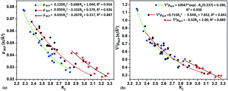
For weak C–H⋯O intermolecular interactions, the electron density and the Laplacian were observed in the range of 0.0232–0.0676 e Å−3 and 0.320–0.923 e Å−5, respectively. The bond dissociation energy for the C–H⋯O interaction is in the range of 0.63–2.02 kcal mol−1. In most of the cases the Rij (the bond path distance) values for C–H⋯O varies from 2.56 Å to 3.08 Å, whereas in some molecular pairs of 26DFBC (IV and V), 35DFBC (III) and 345TFBC (I and II), the Rij values are in the range of 2.38–2.47 Å. For the C–H⋯Cl and C–H⋯F intermolecular interactions the electron density and the Laplacian were observed in the range of 0.0228–0.0417; 0.0277–0.0776 e Å−3 and 0.285–0.507; 0.415–1.149 e Å−5, respectively. The short C–H⋯F was observed in the case of 25DFBC (VIII and IX) and 345TFBC (VI) with the Rij value of 2.28–2.38 Å. Although the bond path distance for H⋯F is short for VIII and IX (25DFBC) than VI (345TFBC), the directionality is very less compared to VI in 345TFBC. The bond dissociation energies for these short H⋯F were observed in the range of 1.85–2.74 kcal mol−1. In Fig. 10, the variation of electron density and the Laplacian at the BCP for intermolecular C–H⋯F (green line), C–H⋯O (red line) and C–H⋯Cl (black line) interactions with the bond path distance (Rij) is plotted. Munshi et al.63 have shown the exponential dependence (correlation coefficient R = 0.86 and 0.95 for theoretical and experimental charge density analyses, respectively) of the electron density (ρBCP) with the interaction length Rij for C–H⋯X (X = O or Cπ) interaction in coumarin derivatives. Panini et al.64 have also discussed about the exponential dependence (fitting parameter R2 = 0.962) of the electron density (ρBCP) with Rij for C–H⋯F interaction in mixed (fluoro and trifluoromethylated benzanilide compounds). In Fig. 11, we have shown the variation of electron density as well as the Laplacian at the BCP with Rij for intermolecular homo and hetero halogen–halogen interactions like F⋯F (blue line), Cl⋯F (green line) and Cl⋯Cl (red line). The topological parameters, namely the electron density and the Laplacian for the different interactions, have been fitted globally to quadratic/exponential/linear functions, the goodness-of-fit values being high.
 |
| | Fig. 10 Variation of (a) electron density and (b) Laplacian with the bond path distance (Rij) at the BCP for the intermolecular C–H⋯F (blue dots and green line), C–H⋯O (black dots and red line) and C–H⋯Cl (red dots and black line) interactions. | |
 |
| | Fig. 11 Variation of (a) electron density and (b) Laplacian with the bond path distance (Rij) at the BCP for the intermolecular F⋯F (red dots and blue line), Cl⋯F (blue dots and green line) and Cl⋯Cl (black dots and red line) interactions. | |
Hirshfeld surface analysis
The Hirshfeld surfaces65 were mapped with dnorm and the electrostatic potential of a molecule (mapped on the Hirshfeld surface over the range of −0.02 a.u. (red) to +0.02 a.u. (blue)) for all fluorinated benzoyl chlorides (Fig. S18–S21, ESI†) using CrystalExplorer 3.2.56 The presence of a red spot of varying intensity between the interacting atoms (for intermolecular C–H⋯O, C–H⋯Cl, C–H⋯F, Cl⋯Cl F⋯O, F⋯F and Cl⋯F interactions in BC and fluorinated BCs) on the blue surface mapped with dnorm indicates the presence of contacts which are less than or equal to the sum of the van der Waals radii of the two interacting atoms. In addition to that, we have shown the Hirshfeld surface associated fingerprint plots66,67 for all fluorinated benzoyl chlorides (including BC) in Fig. S22 (ESI†). In the fingerprint plots, the sharp spikes at lower de and di values indicate intermolecular F⋯H and O⋯H–C interactions and the spikes (represented by red arrows) at higher de and di values indicate intermolecular Cl⋯H interactions. The small spikes in the fingerprint plot indicate the short atom⋯atom contact present in the crystal packing. Fig. S23 (ESI†) shows the relative percentage contribution for various atom⋯atom contacts for the corresponding individual molecules in the crystal packing. Fig. 12 shows the variation of percentage contribution in F⋯H and F⋯F contacts in the crystal packing of fluorinated benzoyl chlorides. From this plot, it was observed that F⋯F contribution is increased [towards 345TFBC (25.4% for molecule 1 and 16.2% for molecule 2)] with the addition of more fluorine atoms on the phenyl ring, i.e. the participation of fluorine atoms in C–H⋯F intermolecular interactions is decreased in comparison to the formation of F⋯F contacts. In the case of 24DFBC (28%) and 35DFBC (26.4%), the H⋯F contribution is high compared to the other mono-, di- and tri-fluorinated benzoyl chlorides wherein this value is very less (4.3%) for 345TFBC-2. As we can see from Fig. 12, the contribution from the F⋯F contacts is very less for 2FBC, 4FBC and 24DFBC, and subsequently the electrostatic contributions for these structures towards the total lattice energy are high even for 25DFBC and 26DFBC in comparison to the other fluorinated analogues. Thus the overall Hirshfeld surface associated fingerprint plots help to differentiate the crystal environment between different molecules as well as the symmetry independent molecules present in the asymmetric unit.
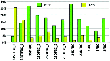 |
| | Fig. 12 Relative contribution of atom⋯atom contacts (H⋯F and F⋯F) in the crystal packing. | |
Tuning the electrostatic nature by successive fluorination
The molecular electrostatic potential (obtained from Gaussian 09 using the DFT-B3LYP/6-311G** basis set) of benzoyl chlorides and its fluorinated derivatives for the crystal geometry were mapped over the range of −0.02 a.u. (red) to 0.02 a.u. (blue). The deep red color region around the oxygen atom and the chlorine atom of the carbonyl group and the vicinal fluorine atom (ortho-substituted) shows the negative ESP and the deep blue color region around the aromatic hydrogen atom shows the positive ESP (Fig. 13). The chlorine atom shows the positive ESP region (green to cyan color denoted with an arrow), i.e., electron deficient, which can interact non-covalently with the other negative (electron rich) center of other molecules. The fluorine atoms attached at the para and meta positions of the phenyl ring have less negative ESP (yellowish green color) compared to the fluorine atoms attached at the ortho position (deep red color). It is observed that the ESP of the phenyl ring changes from green color (BC) to blue color (for 345TFBC). This means that the electron deficiency of the phenyl ring increases with the addition of fluorine atoms in the phenyl ring. It is of interest to note that the region of positive ESP from the donor side interacts with the negative ESP associated with the electronegative atoms. This also manifests in distances between the interacting donor and acceptor atoms being significantly less than the sum of the vdW radii in cases where the magnitude of electrostatic complementarity is high.
 |
| | Fig. 13 ESP molecular electrostatic potential (MESP) of benzoyl chloride and fluorinated benzoyl chlorides mapped from −0.02 a.u. to +0.02 a.u. | |
Summary
In this study, the three-dimensional structures of fluorinated benzoyl chlorides (3FBC, 35DFBC and 345TFBC) have been determined via an in situ cryocrystallization technique. The supramolecular building blocks are constituted by various weak intermolecular interactions and a cooperative interplay which maximise the attraction and minimize the repulsion between the approaching atoms governing the formation of molecular sheets. They have their origin in the contents of the molecular species responsible for the existence of pre-nucleation aggregates which further grown in different directions leading to the formation of the observed crystal structures. The π⋯π stacking interaction acts as the primary molecular building unit in these structures resulting in molecular columns. These molecular columns are interlinked by a multitude of weak C–H⋯O/F/Cl interactions and halogen⋯halogen contacts which template the secondary supramolecular motifs. These weak interactions are instrumental in tuning the growth of the π⋯π stacked primary building blocks with remarkable variety with varying modes of fluorine substitution. The models delineated in this study provide a preliminary fundamental understanding of the phenomena of crystal nucleation and growth which illustrate that atom⋯atom interactions for the most simple of molecules is an extremely complex process which involves sampling of millions of configurations before an observed structure is realized. This also illustrates the fact that nature always tends to maximize the number of interactions between the participating atoms maintaining the energetics which favour their existence under a suitable set of conditions. Future studies will aim to unravel the role of heavier halogens of benzoyl chlorides in the formation of solids.
Acknowledgements
D. D. and S. B. thank IISER Bhopal for the research fellowship. We would like to thank IISER Bhopal for the research facilities and infrastructure and DST-SERB for research funding.
Notes and references
- G. R. Desiraju, J. Am. Chem. Soc., 2013, 135, 9952–9967 CrossRef CAS PubMed.
- S. L. Cockcroft and C. A. Hunter, Chem. Commun., 2006, 3806–3808 RSC.
- R. Berger, G. Resnati, P. Metrangolo, E. Weber and J. Hulliger, Chem. Soc. Rev., 2011, 40, 3496–3508 RSC.
- D. Chopra, Cryst. Growth Des., 2012, 12, 541–546 Search PubMed.
- D. Chopra and T. N. G. Row, CrystEngComm, 2011, 13, 2175–2186 RSC.
-
P. Panini and D. Chopra, Hydrogen Bonded Supramolecular Structures, Lecture Notes in Chemistry, Springer, Berlin, 2014, vol. 87, pp. 37–67 Search PubMed.
- V. Gouverneur and K. Seppelt, Chem. Rev., 2015, 115, 563–565 CrossRef CAS PubMed.
-
I. Ojima, Fluorine in Medicinal Chemistry and Chemical Biology, Wiley-Blackwell, Chichester, West Sussex, UK, 2009 Search PubMed.
- S. Purser, P. R. Moore, S. Swallow and V. Gouverneur, Chem. Soc. Rev., 2008, 37, 320–330 RSC.
- I. Ojima, J. Org. Chem., 2013, 78, 6358–6383 CrossRef CAS PubMed.
- W. K. Hagmann, J. Med. Chem., 2008, 51, 4360–4369 CrossRef PubMed.
- J.-P. Begue and D. Bonnet-Delpon, J. Fluorine Chem., 2006, 127, 992–1012 CrossRef CAS.
- C. Isanbor and D. O'Hagan, J. Fluorine Chem., 2006, 127, 303–319 CrossRef CAS.
- H. Roesky, Nat. Chem., 2010, 2, 240 CrossRef CAS PubMed.
- A. Schwarzer and E. Weber, Cryst. Growth Des., 2008, 8, 2862–2874 Search PubMed.
- A. Schwarzer, W. Seichter, E. Weber, H. Stoeckli-Evans, M. Losadac and J. Hulliger, CrystEngComm, 2004, 6, 567–572 RSC.
- V. Vasylyeva and K. Merz, J. Fluorine Chem., 2010, 131, 446–449 CrossRef CAS.
- A. Olejniczak, A. Katrusiak and A. Vij, J. Fluorine Chem., 2008, 129, 173–177 CrossRef CAS.
- R. Dubey and G. R. Desiraju, Chem. Commun., 2014, 50, 1181–1184 RSC.
- K. Merz, Cryst. Growth Des., 2006, 6, 1615–1619 Search PubMed.
- A. G. Dikundwar and T. N. G. Row, Cryst. Growth Des., 2012, 12, 1713–1716 Search PubMed.
- V. R. Hathwar, S. M. Roopan, R. Subhashini, F. N. Khan and T. N. G. Row, J. Chem. Sci., 2010, 122, 677–685 CrossRef CAS.
- M. Capdevila-Cortada, J. Castello and J. J. Novoa, CrystEngComm, 2014, 16, 8232–8242 RSC.
- J. A. R. P. Sarma and G. R. Desiraju, Acc. Chem. Res., 1986, 19, 222–228 CrossRef CAS.
- S. L. Price, A. J. Stone, J. Lucas, R. S. Rowland and A. E Thomley, J. Am. Chem. Soc., 1994, 116, 4910–4918 CrossRef CAS.
- D. Sisak, L. B. McCusker, G. Zandomeneghi, B. H. Meier, D. Blaser, R. Boese, W. B. Schweizer, R. Gilmour and J. D. Dunitz, Angew. Chem., Int. Ed., 2010, 49, 4503–4505 CrossRef CAS PubMed.
-
R. Boese and M. Nussbaumer, in In situ Crystallization Techniques In Organic Crystal Chemistry, ed. D. W. Jones, Oxford University Press, Oxford, 1994, pp. 20–37; OHCD: http://www.sci.ohcd.eu Search PubMed.
- J. A. K. Howard and M. R. Probert, Science, 2014, 343, 1098–1102 CrossRef CAS PubMed.
- J. Ulrich, Cryst. Growth Des., 2004, 4, 879–880 Search PubMed.
- D. Chopra and T. N. G. Row, J. Ind. Inst. Sci., 2007, 87, 167–211 CAS.
- D. Dey and D. Chopra, Resonance, 2014, 19, 1104–1114 CrossRef CAS.
- D. Das, R. Banerjee, R. Mondal, J. A. K. Howard, R. Boese and G. R. Desiraju, Chem. Commun., 2006, 555–557 RSC.
- D. Chopra, V. Thiruvenkatam and T. N. G. Row, Cryst Growth Des., 2006, 6, 843–845 Search PubMed.
- A. G. Dikundwar and T. N. G. Row, Cryst. Growth Des., 2014, 14, 4230–4235 Search PubMed.
- V. Vasylyeva and K. Merz, Cryst. Growth Des., 2010, 10, 4250–4255 Search PubMed.
- I. D. H. Oswald, D. R. Allan, W. D. S. Motherwell and S. Parsons, Acta Crystallogr., 2005, B61, 69–79 CAS.
- A. R. Choudhury, N. Winterton, A. Steiner, A. I. Cooper and K. A. Johnson, J. Am. Chem. Soc., 2005, 127, 16792–16793 CrossRef CAS PubMed.
- A. R. Choudhury, N. Wintherton, A. Steiner, A. I. Cooper and K. A. Johnson, CrystEngComm, 2006, 8, 742–745 RSC.
- R. Boese, D. Blaser and G. Jansen, J. Am. Chem. Soc., 2009, 131, 2104–2106 CrossRef CAS PubMed.
- M. T. Kirchner, R. Boese, E. W Billups and L. R. Norman, J. Am. Chem. Soc., 2004, 126, 9407–9412 CrossRef CAS PubMed.
- R. Boese, M. T. Kirchner, W. E Billiups and L. R. Norman, Angew. Chem., Int. Ed., 2003, 42, 1961–1963 CrossRef CAS PubMed.
- D. Khamar, J. Zeglinski, D. Mealey and A. C. Rasmuson, J. Am. Chem. Soc., 2014, 136, 11664–11673 CrossRef CAS PubMed.
- S. P. Thomas, R. Sathishkumar and T. N. Guru Row, Chem. Commun., 2015, 51, 14225–14258 Search PubMed.
- R. J. Davey, S. L. M. Schroeder and J. H. T. Horst, Angew. Chem., Int. Ed., 2013, 52, 2166–2179 CrossRef CAS PubMed.
- A. J. L. Jesus, L. I. N. Tome, E. S. Eusebio and J. S. Redinha, J. Phys. Chem. B, 2006, 110, 9280–9285 CrossRef CAS PubMed.
- S. Parveen, R. J. Davey, G. Dent and R. G. Pritchard, Chem. Commun., 2005, 1531–1533 RSC.
- P. G. Debenebetti and F. H. Stillinger, Nature, 2001, 410, 259–267 CrossRef PubMed.
- C. A. Angell, Sci., New Ser., 1995, 267, 1924–1935 CAS.
- H. Z. Cummnis, Phys. Rev., 1996, E54, 5870–5872 Search PubMed.
- S. K. Nayak, M. K. Reddy, D. Chopra and T. N. G. Row, CrystEngComm, 2012, 14, 200–210 RSC.
- D. Dey, S. Bhandary, A. Sirohiwal, V. R. Hathwar and D. Chopra, Chem. Commun., 2016, 52, 7225–7228 RSC.
- A. Gavezzotti, CrystEngComm, 2003, 5, 429–438 RSC.
- J. D. Dunitz and A. Gavezzotti, Cryst. Growth Des., 2005, 5, 2180–2189 Search PubMed.
- J. D. Dunitz and A. Gavezzotti, Angew. Chem., Int. Ed., 2005, 44, 1766–1787 CrossRef CAS PubMed.
- J. D. Dunitz and A. Gavezzotti, Chem. Soc. Rev., 2009, 38, 2622–2633 RSC.
-
M. J. Turner, J. J. McKinnon, S. K. Wolff, D. J. Grimwood, D. Jayatilaka and M. A. Spackman, CrystalExplorer, version 3.2, University of Western Australia, Crawley, Australia, 2014 Search PubMed.
-
(a) M. J. Turner, S. P. Thomas, M. W. Shi, D. Jayatilaka and M. A. Spackman, Chem. Commun., 2015, 51, 3735–3738 RSC;
(b) M. J. Turner, S. Grabowsky, D. Jayatilaka and M. A. Spackman, J. Phys. Chem. Lett., 2014, 5, 4249–4255 CrossRef CAS PubMed.
-
(a) M. W. Shi, S. P. Thomas, G. A. Koutsantonis and M. A. Spackman, Cryst. Growth Des., 2015, 15, 5892–5900 CrossRef CAS;
(b) S. P. Thomas, D. Jayatilaka and T. N. Guru Row, Phys. Chem. Chem. Phys., 2015, 17, 25411–25420 RSC.
- D. Dey, S. P. Thomas, M. A. Spackman and D. Chopra, Chem. Commun., 2016, 52, 2141–2144 RSC.
-
R. F. W. Bader, Atoms in Molecules: A Quantum Theory, Oxford University Press, Oxford, UK, 1990 Search PubMed.
-
V. G. Tsirelson, in The Quantum Theory of Atoms in Molecules: From Solid State to DNA and Drug Design, ed. C. Matta and R. Boyd, Wiley-VCH, Weinheim, Germany, 2007, ch. 10.45 Search PubMed.
- U. Koch and P. L. A. Popelier, J. Phys. Chem., 1995, 99, 9747–9754 CrossRef CAS.
- P. Munshi and T. N. G. Row, J. Phys. Chem. A, 2005, 109, 659–672 CrossRef CAS PubMed.
- P. Panini and D. Chopra, Cryst. Growth Des., 2014, 14, 3155–3168 Search PubMed.
- M. A. Spackman and D. Jayatilaka, CrystEngComm, 2009, 11, 19–32 RSC.
- M. A. Spackman and J. J. Mckinnon, CrystEngComm, 2002, 4, 378–392 RSC.
- J. Mckinnon, D. Jayatilaka and M. A. Spackman, Chem. Commun., 2007, 3814–3816 RSC.
|
| This journal is © the Owner Societies 2016 |
Click here to see how this site uses Cookies. View our privacy policy here. 
 Open Access Article
 This Open Access Article is licensed under a Creative Commons Attribution-Non Commercial 3.0 Unported Licence
 b and
Deepak
Chopra
*a
b and
Deepak
Chopra
*a