
 Open Access Article
 This Open Access Article is licensed under a
 Creative Commons Attribution 3.0 Unported Licence
Orientation and stability of a bi-functional aromatic organic molecular adsorbate on silicon†
K. M.
O'Donnell
a,
H.
Hedgeland‡
b,
G.
Moore
bc,
A.
Suleman
bc,
M.
Siegl
bc,
L.
Thomsen
d,
O.
Warschkow
e and
S. R.
Schofield
 *bc
*bc
aDepartment of Physics, Astronomy and Medical Radiation Science, Curtin University, Bentley, WA 6102, Australia
bLondon Centre for Nanotechnology, University College London, London, WC1H 0AH, UK. E-mail: s.schofield@ucl.ac.uk
cDepartment of Physics and Astronomy, University College London, London, WC1E 6BT, UK
dAustralian Synchrotron, Clayton, VIC 3168, Australia
eCentre for Quantum Computation and Communication Technology, School of Physics, University of Sydney, Sydney, NSW 2006, Australia
First published on 15th September 2016
Abstract
In this work we combine scanning tunneling microscopy, near-edge X-ray absorption fine structure spectroscopy, X-ray photoemission spectroscopy and density functional theory to resolve a long-standing confusion regarding the adsorption behaviour of benzonitrile on Si(001) at room temperature. We find that a trough-bridging structure is sufficient to explain adsorption at low coverages. At higher coverages when steric hindrance prevents the phenyl ring lying flat on the surface, the 2+2 cycloaddition structure dominates.
Introduction
The modification of semiconductor surfaces through the covalent attachment of organic compounds holds great potential for the creation of hybrid organic-semiconductor devices where organic functionality is integrated with conventional semiconductor technology.1–4 Organic molecules exhibit a broad range of optical, electronic, chemical, and biological properties making them suitable candidates for application in novel opto-electronic and bio-electronic devices. Notwithstanding this enormous potential, current electronic device technology is strongly rooted in solid-state crystalline semiconductor materials, primarily silicon. Thus there is currently a strong impetus for the development of methods to interface organic functionality with silicon device technology, and a key to this goal is understanding and controlling the organic–semiconductor interactions at the atomic-scale. Determining the adsorption structures of organic molecules on the technologically important Si(001) surface is an important fundamental step toward this goal.5–14Recent advances in atomic-scale imaging, photoelectron and X-ray absorption spectroscopy, and theoretical calculations now provide us with the ability to determine the structure of surface adsorbates with atomic-scale precision. Scanning tunnelling microscopy (STM) can provide atomically-resolved images of individual adsorbates, often resolving key features that are critical to the correct identification of the structures. However, detailed chemical information cannot be directly determined from STM data, and it is suited mainly to submonolayer surface coverages, making it useful to analyse STM results in combination with complementary techniques. X-ray photoemission spectroscopy (XPS) and near-edge X-ray absorption fine structure spectroscopy (NEXAFS) provide detailed insight into the type, frequency, and directionality of chemical bonds and functional groups. This information is spatially averaged over macroscopic regions and thus may reflect an average of different adsorbate configurations. Density functional theory (DFT) can provide detailed adsorption energies and reaction barriers for a multitude of possible chemical and structural configurations. Nevertheless, the sensitivity of the results to computational parameters, coupled with the shear number of possible configurations, makes it difficult to provide absolute statements about the expected structures without comparison to experimental data. When used in isolation, each of these methods is prone to uncertainty or error; however, in combination they form a powerful toolset to resolve the organic-semiconductor interface at the atomic scale.
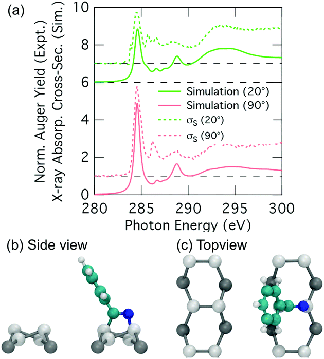
The adsorption of benzonitrile (C6H5CN) to the Si(001) surface is of interest because the molecular adsorbate can be repositioned on the Si(001) surface using STM manipulation and subsequently used as anchor points for the guided self-assembly of metal-atom chains of single-atom width.15 From a chemical perspective, benzonitrile is interesting as an adsorbate with bifunctional reactivity; both the phenyl ring and the nitrile group can react with the silicon surface. The STM image data reported by Belcher et al.15 shows that only a single adsorbate structure exists when benzonitrile is dosed to very low coverages at room temperature. Moreover, the adsorbate is seen to bridge across the trench between two adjacent dimer rows. In conjunction with DFT calculations the adsorbate configuration was identified as the structure shown in Fig. 1a. In this configuration, the phenyl ring is attached in a C2C5 di-σ arrangement to two adjacent dimers on one dimer row, and the nitrile group is datively bonded to a down silicon atom on the other dimer row. In the following we will refer to this configuration as the trough-bridge tripod structure, or trough-bridge for short.
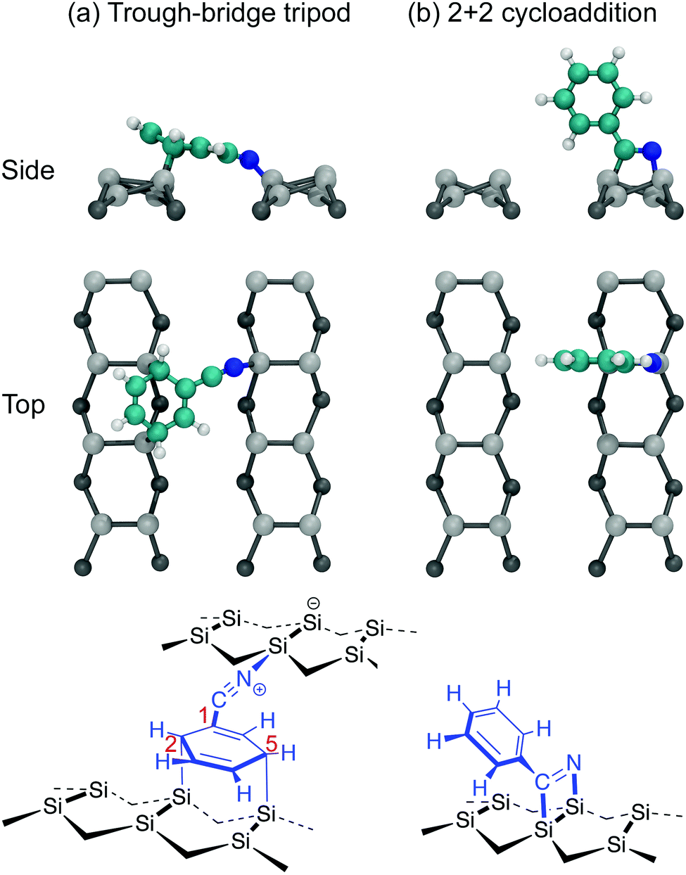 | ||
| Fig. 1 Models for benzonitrile adsorption on Si(001) referred to in this work: (a) the trough-bridge tripod structure, (b) 2+2 cycloaddition. Top and side view ball and stick models are shown together with chemical schematics. | ||
These findings are at odds with earlier reports. Tao et al.16 used XPS, temperature-programmed desorption (TPD), high-resolution electron energy loss spectroscopy (HREELS), and DFT calculations to conclude that the best fit to their experimental data is the 2+2 cycloaddition structure shown in Fig. 1b. In this configuration the adsorbate is attached to the surface via a 1,2-dipolar cycloaddition between the nitrile group and a silicon dimer. A subsequent theoretical study, which considered a broad range of possible adsorbate configurations, concluded that the 2+2 cycloaddition structure is energetically preferred.17 Later, Rangan et al.18 performed a combined NEXAFS and DFT study and concluded that the 2+2 cycloaddition structure can account only for a subset of features occurring in the NEXAFS spectra, and that there must also be some fraction of the adsorbates that are bonded to the surface via the phenyl ring. Rangan et al. argued that the best overall fit to their nitrogen K-edge spectra is a combination of the 2+2 cycloaddition structure and a C2C5 di-σ structure where the nitrogen is not bonded to the substrate. They proposed these species are both present from the beginning of deposition. It should be noted, that neither of these earlier reports considered the trough-bridge tripod structure (Fig. 1a) proposed in ref. 15.
In this work, we reconcile these disparate interpretations by recording XPS and NEXAFS spectra at both low and high coverages. This allows us to compare the low coverage data of the STM-based work of ref. 15 with the high-coverage spectroscopy measurements reported in ref. 16 and 18. We analyse the results with the aid of simulated NEXAFS spectra that we generate via DFT, and we also perform a number of coverage dependent STM measurements. We show that at very low coverage the adsorption is dominated by the trough-bridge tripod structure, while at higher coverages the trough-bridge structure coexists with the 2+2 cycloaddition structure.
Methods
Experiment
Experiments were carried out in situ under ultrahigh vacuum (UHV) on the soft X-ray beamline of the Australian Synchrotron.19 The silicon substrates for these experiments were 12 × 2 mm chips cleaved from 0.04–0.06 Ω cm Sb-doped (n-type) silicon (001) wafers (Virginia Semiconductor Inc.). Each silicon substrate was mounted with tantalum clips in a direct-current heating arrangement and degassed at ≈550 °C overnight prior to first use. Before each measurement or benzonitrile dose, the silicon sample was flash-annealed to ≈1200 °C (10 A, 6 V direct current) for 10 s with a programmed cool-down over 2 minutes. Silicon samples were allowed to cool for 30 minutes after flashing before dosing with benzonitrile. Benzonitrile (>99.0%, Sigma Aldrich) was purified by freeze/pump/thaw cycles and checked for residual water contamination using a UHV residual gas analyzer (Stanford Research Systems SRS100) and dosed from vapour admitted via a UHV precision leak valve. Dose flux was calculated using the total chamber pressure. Once prepared the samples were transferred under UHV from the dedicated preparation chamber to the adjacent analysis chamber for XPS and NEXAFS measurements, which were taken at room temperature with a base pressure of better than 2.0 × 10⁻¹⁰ mbar.The photon energy for XPS measurements was set to 440 eV to maximise sensitivity to nitrogen. Gold 4f core level spectra from a gold foil mounted on the analysis manipulator and in electrical contact with the sample were taken for energy calibration. Nitrogen 1s, carbon 1s, and silicon 2p core level spectra were acquired subsequent to the gold 4f measurement. Carbon and nitrogen K-edge NEXAFS spectra were then acquired for five angles between normal (90°) and grazing (20°) photon incidence. The acquisition mode was partial electron yield (PEY) using a micro-channelplate detector and a repelling grid energy of 230 V for carbon and 340 V for nitrogen. Normalization of the PEY signal was performed via the clean monitor method20 using a clean Si(001) surface and the flux signal from a 50% transmissive gold grid placed in the beam path upstream of the sample. The sequence of XPS measurements was repeated after completing the NEXAFS measurement to ensure there had been no changes due to contamination or beam damage.
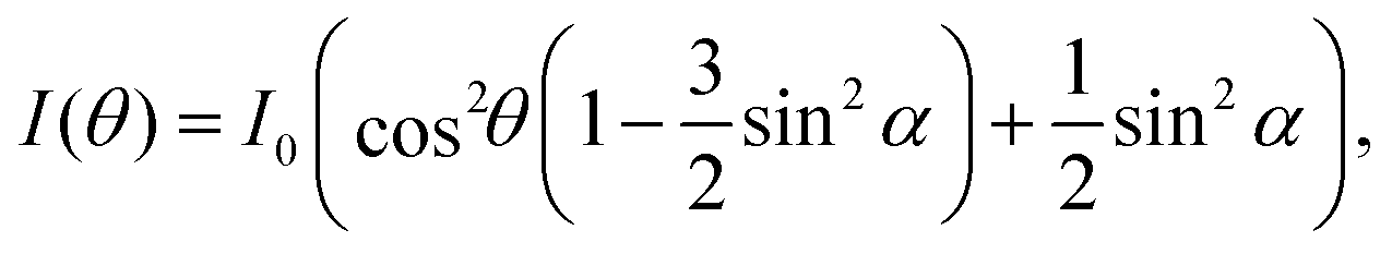
NEXAFS spectra were normalised using standard procedures20,21 as implemented in the QANT software package.22 Briefly, the spectrum pre-edge was subtracted and the post-edge normalized to unity and the spectra were lightly smoothed. Key π* resonances in the near-edge spectra were fit with Gaussian peaks; the area of these resonances as a function of angle was then curve fit to elucidate the polar angle of the π* orbital vector. The underlying symmetry of the Si(001) substrate is four-fold, hence the appropriate equation is eqn (9.16a) in ref. 21; i.e.
 | (1) |
Scanning tunneling microscopy was performed in a separate UHV system using an Omicron LT-STM system operated at 77 K with a base pressure below 5 × 10⁻¹¹ mbar. STM tips were prepared by electrochemically etching 0.25 mm diameter polycrystalline tungsten wire with subsequent in vacuo electron-beam annealing and field emission. Samples were prepared using the same procedure as detailed above for the NEXAFS and XPS experiments.
Simulation
Density functional theory calculations were used to compute theoretical NEXAFS spectra for comparison with our experimental spectra. The Si(001) was modelled using a slab model approach with a (4 × 4) in-plane periodic repeat. This corresponds to a unit cell of two rows of four dimers each. The slab model has a thickness of five silicon layers. The non-adsorbing side of the slab is chemically saturated using a dihydride termination. Structure relaxations of the free Si(001) surface and several benzonitrile adsorption configurations were carried out using the FHI-aims code23 using Perdew–Burke–Ernzerhof (PBE) exchange–correlation,24 a tight atom-centred basis set, and a 2 × 2 × 1 Monkhorst–Pack grid. Except for the bottom silicon layer and the hydrogen-termination, all atoms of the slab model and adsorbate were fully relaxed. The atomic positions obtained in this way provide the structure input for our simulation of NEXAFS spectra. These NEXAFS spectra were calculated using a different software, namely the Quantum Espresso package25 and in particular the PWScf and XSpectra26,27 codes, which are based on a projector-augmented wave (PAW) approach.28 In these calculations, we again use PBE exchange–correlation and a 2 × 2 × 1 k-point grid. A plane wave cutoff of 65 Ry (884 eV) was applied.Simulated NEXAFS spectra were computed using a four-step process. First, a standard self-consistent field (SCF) calculation was carried out to give a reference ground state energy for the benzonitrile structure considered. Second, for each absorber atom (carbon and nitrogen in our case), a separate SCF calculation was carried out with a modified ‘transition potential’ PAW potential at the absorber site, which has one half of an electron removed from the core-level of interest.29 Third, the electron density from each of these absorber calculation is used with the XSpectra code to generate a set of unoccupied spectra along six photon polarization directions, namely, (100), (010), (001), (110), (101) and (011). Linear combinations of these spectra can be used to derive the absorber spectrum for an arbitrary polarization (see Supplementary methodology for details, ESI†). And last, the spectra from each absorber site are combined using a transition energy. This energy is computed using another modified PAW potential at each absorber site, now with a full electron removed from the core level of interest. The energy difference between this ‘full-core-hole’ and the ground state calculation gives the raw transition energy for each absorber. The transition energy is further corrected by adding the band gap obtained from the transition-potential calculation. This correction accounts for variations in the band gap as a function of the core hole location; however, the effect is typically small. Shifted by the transition energy, the individual absorber atom spectra are combined in a complete NEXAFS spectrum in a physically meaningful way. We note in passing that the method of Mizoguchi30 for calculating the transition energy is not required here because the PAW approach uses all-electron energies, and thus no double-counting of pseudopotential energies occurs.
Results and discussion
NEXAFS
Fig. 2 shows carbon and nitrogen K-edge NEXAFS spectra as a function of incident angle for two benzonitrile doses, 0.225 L (low dose) and 1.35 L (high dose), which produced submonolayer and nearly saturated adsorbate coverages, respectively (see below). The dose rate was kept constant for both doses by maintaining a constant chamber pressure of 1.0 × 10⁻⁹ mbar.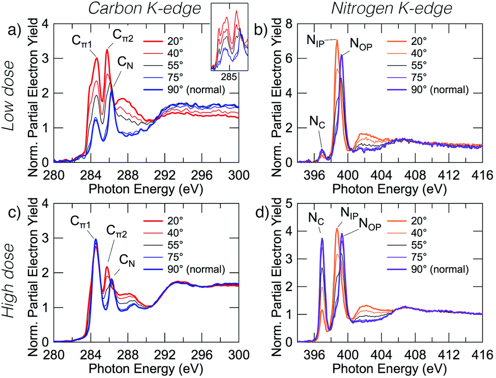 | ||
| Fig. 2 Carbon and nitrogen K-edge NEXAFS spectra for low (0.225 L) and high (1.35 L) benzonitrile doses. The low and high dose carbon spectra (a and c) display prominent peaks at 284.5, 285.5, and 286.2 eV that we label Cπ1, Cπ2 and CN, and an exciton peak at 283.8 eV. The inset in panel (a) shows unsmoothed data. The low and high dose nitrogen spectra (b and d) display prominent peaks at 397.0, 398.7, and 399.3 eV which we have labeled NC, NIP, and NOP. | ||
The low dose carbon K-edge spectra (Fig. 2a), shows three prominent resonances at 284.5, 285.5, and 286.2 eV that we label Cπ1, Cπ2 and CN. We will show that these arise from excitation of carbon atoms to π* anti-bonding states associated with the atoms of the ring portion of the adsorbates (Cπ1, Cπ2) and from excitation of the nitrile carbon (CN). It can be seen that the Cπ1 resonance shows strong linear dichroism with highest intensity at glancing incidence. A fit of the peak areas as a function of angle to eqn (1) yields a π-plane tilt angle of 41.5 ± 2.0° above the surface plane. Similarly, the Cπ2 resonance displays strong dichroism yielding a π-plane tilt angle of 28.1 ± 5.0°. In contrast no dichroism is evident for the CN resonance. The broad feature centred on 288 eV can be attributed to C–H σ* resonances, which are known to occur in close proximity to the ionisation potential.31,32 There is a further peak that appears as a shoulder on the low energy side of the Cπ1 resonance. In the unsmoothed data, this shoulder appears as a very sharp instrument-limited (width ≈0.2 eV; see inset in Fig. 2a) resonance at 283.8 eV. The very narrow linewidth and its position at the leading edge of the step suggests that this is a core exciton resonance similar to that observed for other small aromatic and conjugated molecules,33 and also in bulk diamond34 and graphite.35
The nitrogen K-edge at low coverage (Fig. 2b) displays three resonances at 397.0, 398.7, and 399.3 eV which we have labeled NC, NIP, and NOP, respectively. The subscript labels represent cycloaddition, in-plane, and out-of-plane, whose meanings will become clear below. The NC peak appears to display some dichroism; however, the low peak intensity relative to the noise level precluded an accurate determination of the tilt angle. Both NIP and NOP resonances have strong dichroism but with opposite trends; NIP is most intense at glancing incidence whereas NOP is most intense at normal incidence, hence the in-plane and out-of-plane labels. The corresponding tilt angles from eqn (1) are 27.9 ± 1.1° and 66.3 ± 0.8° respectively.
The high coverage NEXAFS spectra for carbon and nitrogen (Fig. 2c and d) are similar to the low coverage spectra: the Cπ2, CN, NIP, and NOP peaks remain essentially unchanged. However, there are two critical changes: (1) the Cπ1 resonance no longer displays any dichroism (Fig. 2c), and (2) the NC resonance shows a large increase in oscillator strength relative to features NIP and NOP such that the resulting tilt angle can be determined to be 71.2 ± 1.6°. We note further that a previous measurement exists for the high-coverage nitrogen K-edge NEXAFS (Fig. 7 in ref. 18) and that our corresponding measurement (Fig. 2d) is in good agreement with this prior work.
The observation that some peaks remain unchanged while others display dramatic changes suggests that additional adsorption structures are contributing new spectral features in the high coverage spectra. In order to understand the relative contributions and structural origins of each, it is necessary to disentangle the spectra, which we do using coverage dependent XPS measurements.
XPS
We consider core-level XPS spectra in order to distinguish benzonitrile adsorption configurations by their nitrogen chemistry. Fig. 3 shows XPS nitrogen 1s core level spectra for the low and high doses. Both coverages show three peaks labeled N1, N2, and N3, which are located at 397.7, 398.5 and 400.3 eV in the high coverage spectra. There is a small shift of <0.2 eV in the low coverage spectra, which we attribute to a band bending effect due to a changing adsorbate dipole moment.3 Peak N2 is a contamination peak from the analysis chamber background that was present prior to dosing; the associated NEXAFS spectrum is a featureless step edge that we recorded separately. Peak N1 is small at low coverage but increases dramatically at the higher coverage to become the dominant peak. In contrast, peak N3 increases only slightly in the high coverage spectrum.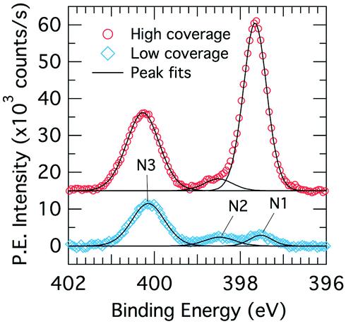 | ||
| Fig. 3 X-ray photoelectron spectroscopy N 1s core level spectra for low (0.225 L; blue diamonds) and high (1.35 L; red circles) benzonitrile doses on Si(001) at room temperature. | ||
The two benzonitrile-related XPS peaks N1 and N3 suggest that there are at least two distinct kinds of nitrogen chemistry occurring during benzonitrile adsorption and that the ratio between these changes dramatically with coverage. The large binding energy separation between the two XPS peaks (2.6 eV) indicates significant differences in charge transfer between the nitrogen sites and the bonding atoms. Thus, the XPS spectra shown in Fig. 3 suggest that the structure (or structures) leading to peak N3 in the XPS occur first and therefore dominate the low coverage spectra. As the coverage increases, the surface begins to saturate but benzonitrile uptake continues in the form of a new structure (or structures) that produces XPS peak N1.
The value of 397.7 eV for peak N1 is consistent with rehybridization of the nitrile group as observed in adsorption of benzonitrile on metal surfaces (e.g. Ni, Pd).36 This suggests that peak N1 (dominant at high coverage) results from an adsorbate configuration involving a disruption to the nitrile bond. On the other hand, the value of 400.3 eV for peak N3 (dominant at low coverage) is higher than the value reported for a physisorbed multilayer of benzonitrile at cryogenic temperature (399.8 eV).36 This suggests an intact nitrile group with some degree of charge transfer from the nitrogen site for our N3 peak. Since there is already a triple bond to the nitrile carbon, the most likely form of charge transfer of this kind is a dative bond resulting in a positive formal charge on the nitrogen site. A shift to higher binding energies has been observed in this situation previously by Tao et al.37 in a study of pyridine adsorbed on Si(001).
NEXAFS decomposition
The XPS data suggests a strong preference for the adsorbates to adopt one configuration at low coverage with an increasing preference for an alternate structure as the coverage approaches saturation. The chemical shifts in the nitrogen 1s XPS suggests these initial and saturation adsorbate structures have nitrogen attachment chemistries consistent with the trough-bridge and 2+2 cycloaddition configurations, respectively. We can gain further insight by using the relative fractional contributions of the N1 and N3 XPS component peaks to decompose the NEXAFS spectra into corresponding separate component spectra, and then comparing these with simulated NEXAFS spectra. XPS peak N3 is associated with the structures that form on the initial adsorption at low coverage and peak N1 is associated with the structures that form at higher coverages. We label the areas of these peaks A and B, respectively, such that at low coverage we have peak areas AL and BL, and at high coverage we have AH and BH. We are then able to decompose the NEXAFS spectra because we know that at each coverage these are linear combinations of spectral contributions from the separate structures in the same proportions as measured in the XPS spectra. Thus, if the low and high coverage NEXAFS spectra are labelled σL and σH, and the (unknown) NEXAFS component spectra arising from the initial and saturation coverage adsorbate structures are σI and σS, then we can write the relative fractional spectral contributions to each NEXAFS spectrum as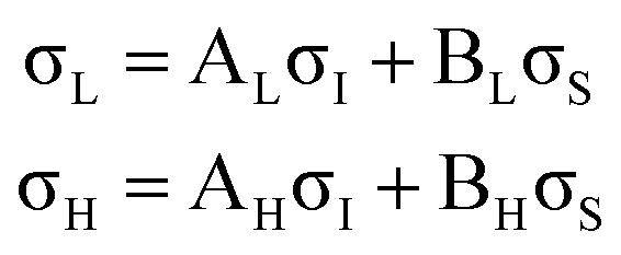 | (2) |
The deconvolved spectra for carbon and nitrogen are shown in Fig. 4 and 5, respectively. Note that the σI and σS spectra that reproduce the low- and high-coverage spectra for a given incident angle (e.g., shown in Fig. 4a and c) are identical and only the relative weightings vary such that their addition reproduces the full experimental spectra via eqn (2).
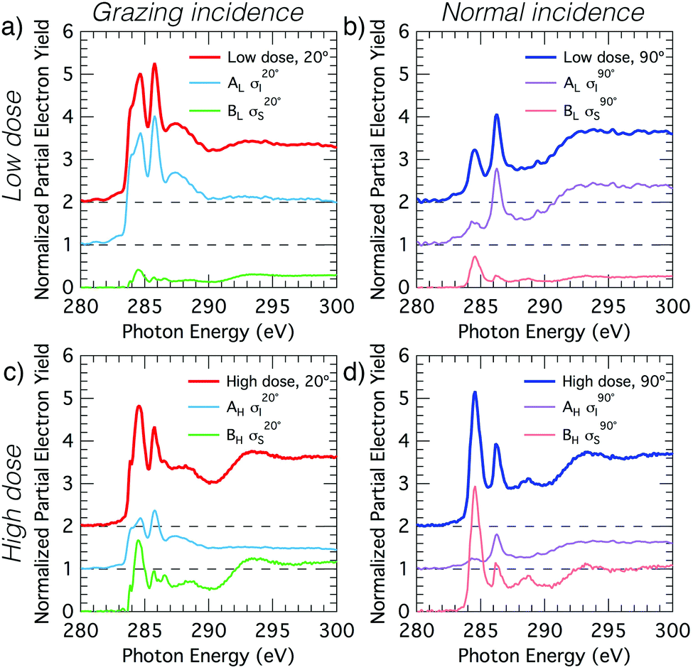 | ||
Fig. 4 Decomposition of the carbon NEXAFS spectra grazing (20°) and normal (90°) angles of incidence. The decomposed spectra  , ,  , ,  , and , and  are displayed with the appropriate weighting AL, BL, AH, and BH such that their sum produces the corresponding full experimental spectrum. The dashed lines show the baseline for the shifted spectra. are displayed with the appropriate weighting AL, BL, AH, and BH such that their sum produces the corresponding full experimental spectrum. The dashed lines show the baseline for the shifted spectra. | ||
 | ||
Fig. 5 Decomposition of the nitrogen NEXAFS spectra grazing (20°) and normal (90°) angles of incidence. The decomposed spectra  , ,  , ,  , and , and  are displayed with the appropriate weighting AL, BL, AH, and BH such that their sum produces the corresponding full experimental spectrum. The dashed lines show the baseline for the shifted spectra. are displayed with the appropriate weighting AL, BL, AH, and BH such that their sum produces the corresponding full experimental spectrum. The dashed lines show the baseline for the shifted spectra. | ||
Simulated NEXAFS: trough-bridge structure
We analyse the deconvolved experimental spectra by simulating NEXAFS spectra of DFT calculated adsorption structures. The STM observation of only the trough-bridge structure at very low coverage15 combined with the XPS data presented and discussed above suggests that a simulated NEXAFS spectrum of the trough-bridge structure is a suitable place to begin the analysis of the deconvolved spectra of the component that dominates at low coverage (σI).Fig. 6a shows simulated grazing and normal incidence carbon K-edge NEXAFS spectra for the trough-bridge model together with the corresponding deconvolved experimental spectra, while Fig. 6b shows the analogous traces for the nitrogen K-edge. It is immediately apparent that there is a remarkable agreement between the simulated and experimental and spectra, providing strong evidence in support of our trough-bridge model (Fig. 1a) as the initial adsorbing product for benzonitrile on Si(001) at low coverage.15 In particular, the simulation reproduces well the Cπ1, Cπ2, and CN resonances in the carbon spectra: the calculated energy separation between Cπ1 and Cπ2 is 1.09 eV and between Cπ2 and CN is 0.79 eV, which is in good agreement with the corresponding experimental values of 1.0 and 0.7 eV (Fig. 2). The simulation also reproduces well the nitrogen peaks, producing both the NIP and NOP features with an energy splitting between them of 0.47 eV that agrees with the value of 0.5 eV from experiment.
 | ||
| Fig. 6 Theoretical NEXAFS spectra at glancing and normal incidence computed for the trough-bridge structure for (a) carbon and (b) nitrogen. The experimental σI spectra appear as dotted lines above the theoretical equivalent. The dashed lines show the baseline for the shifted spectra. | ||
The good agreement at glancing and normal incidence (Fig. 6) demonstrates also that the simulation reproduces the experimental dichroism in both the carbon and nitrogen spectra. We calculate the tilt angles from the simulated spectra in the same way as in the analysis of the experimental spectra by fitting the peak area variation with incident angle to the Stöhr equation (eqn (1)). The theoretical tilt angles for the simulated nitrogen spectra are α(NIP) = 28.1° and α(NOP) = 80.8°, which are in good agreement with the experimental values of 29.5°, 69.3°, respectively. The tilt angles derived from the simulated Cπ resonances, α(Cπ1) = 20.4° and α(Cπ2) = 18.0° are slightly lower than the corresponding experimental values, 31.6° and 28.1°. These slight discrepancies may reflect vibrational effects as discussed further below. Nevertheless, the overall agreement between the deconvolved spectra (σI) corresponding to the dominant species at low coverage and the trough-bridge model simulated spectra is very good for both the carbon and nitrogen K-edge.
Simulated NEXAFS: 2+2 cycloaddition
Fig. 7 shows simulated grazing and normal incidence carbon and nitrogen K-edge NEXAFS spectra for the 2+2 cycloaddition structure alongside the corresponding deconvolved σS experimental spectra. There is excellent agreement between the simulated and experimental nitrogen K-edge NEXAFS (Fig. 7b): the theoretical spectra reproduce all of the main features that are evident in the experimental spectra for glancing and normal incidence. The NC resonance dominates the normal incidence spectrum (90°) and becomes much weaker in the glancing incidence spectrum (20°). The corresponding theoretical tilt angle for the NC resonance is 76.2°, which agrees well with the experimental value of 72.7°.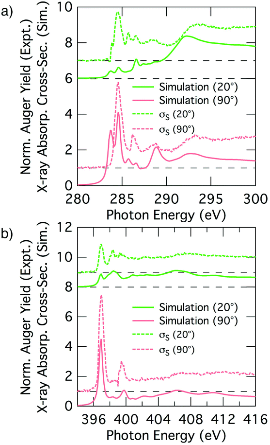 | ||
| Fig. 7 Theoretical NEXAFS spectra computed for the 2+2 cycloaddition structure for (a) carbon and (b) nitrogen at glancing and normal incidence. The experimental σS spectra appear as dotted lines above the theoretical equivalent. The dashed lines show the baseline for the shifted spectra. | ||
The simulated carbon K-edge spectra also reproduce the key features observed in the experimental spectra. In particular, the Cπ1 peak (284.5 eV) that is the most prominent aspect of the σS spectrum is well reproduced, as are other smaller features in the higher energy region of the spectra. A fit to the simulated dichroism produces a tilt-angle for the Cπ1 resonance of 83.9°, which is in qualitative agreement with the experiment but quantitatively larger than the experimental value of 62.2°. Another point of discrepancy is that the simulated spectra show splitting of the Cπ resonance states that is not seen in the experimental σS spectra; this is most evident at the low energy side of the 90° spectra in Fig. 7a.
Thus we have an excellent agreement between simulation and experiment for the nitrogen K-edge spectrum, and overall a good agreement for the carbon spectrum with a couple of points of discrepancy that we will now address. A plausible reason for the discrepancies in the carbon spectra is that we are not accounting for the thermal motion of the adsorbate when generating our NEXAFS simulations, and that this becomes a problem particularly for the phenyl portion of the 2+2 cycloaddition structure where significant vibrational and rotational motion is possible. In principle we could take account of thermal motion by performing a full calculation of a representative spectrum based on many snapshots including vibrational and rotational motion; however, this is computationally prohibitive. Nevertheless, we can gain some insight by considering key perturbations. We consider the rotational motion of the phenyl ring about the C–C linkage to the substrate by simulating the extreme case where the ring is rotated by 90° such that the ring is parallel to the dimer row (Fig. 8b and c). The resulting simulated carbon spectra are shown in Fig. 8a (the nitrogen spectrum is essentially unchanged from Fig. 7b). This shows spectral features in much better agreement with experiment: the dichroism of the dominant carbon resonance at 284.6 eV (62.9°) matches very well with the experimental value of 62.2° and the splitting of this peak has been eliminated. Admittedly, the full 90° rotation is an extreme illustration of the effects of phenyl ring rotation on NEXAFS measurements. However, complete (180°) rotational motion of ring is predicted to occur at an appreciable rate of 107 s−1. This is based on a calculated barrier of 0.36 eV and an assumed Arrhenius attempt frequency of 1013 s−1. This illustrates that considerable rotational motion of the phenyl group occurs in the 2+2 structure. Thus we propose that the 2+2 cycloaddition structure is a good fit to the experimental σS decomposition spectra once thermal effects have been taken into account.
 | ||
| Fig. 8 (a) Theoretical nitrogen K-edge NEXAFS spectra computed for the 2+2 cycloaddition structure with 90° rotation of the phenyl ring. The experimental σS spectra appear as dotted lines above the simulations. The dashed lines show the baseline for the shifted spectra. (b and c) Side and top view structural models. | ||
Identification of NEXAFS peak components
We can gain further insight into the NEXAFS data by decomposing the simulated spectra to elucidate the atomic origins of the individual components. We start by examining the simulated NEXAFS spectrum of gas-phase benzonitrile (Fig. 9a). We find that there are contributions to the Cπ1 resonance at 284.5 eV from the ortho, meta, and para carbons of the phenyl (C2 to C6), while the nitrile carbon atom is essentially the sole contributor to a distinct resonance at 286.4 eV. There is also a small peak at 285.3 eV deriving from the carbon C1 that is also present as a shoulder resonance in the ortho carbons (C2 and C6). This is consistent with the meta-directing character of the nitrile group.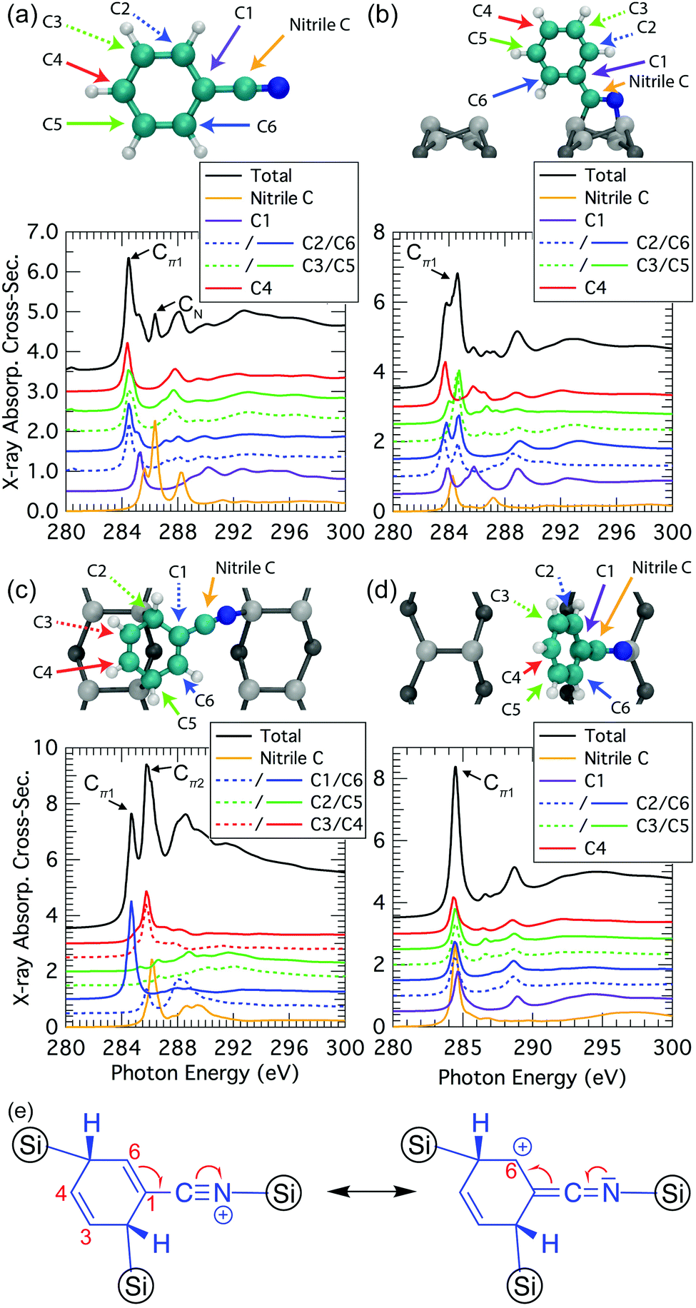 | ||
| Fig. 9 Atomic decomposition of the theoretical carbon K-edge spectrum for various structures: (a) gas-phase benzonitrile; (b) 2+2 cycloaddition (normal incidence); (c) trough-bridge tripod (grazing incidence); (d) 2+2 cycloaddition with 90° rotated phenyl ring (normal incidence). (e) Resonance forms for the trough-bridge tripod. | ||
When benzonitrile is adsorbed on the Si(001) surface, changes in the bonding and delocalization are reflected in changes from the gas phase spectra. In the 2+2 structure (Fig. 9b) the nitrile has converted to a double bond and consequently the 286.4 eV resonance from the nitrile group disappears. Instead, the spectral contribution of the “nitrile” carbon is reminiscent of a conventional double bond. The remaining carbons produce spectral components similar to the gas phase case. However, as noted in our discussion above of the decomposed experimental spectra, there is a clear splitting in the dominant Cπ1 resonance of the theoretical spectrum that is not seen experimentally. The decomposed data in Fig. 9b shows that this is predominantly coming from the meta carbons, supporting our hypothesis that the splitting is a result of the 2+2 structural resonance forms between the phenyl ring and the cyclized nitrile that leaves C2 and C6 with a positive formal charge. Such resonances are only possible when the phenyl ring is planar to the cyclized nitrile. Hence, rotational motion of the phenyl can be expected to reduce or eliminate the split peak, as is illustrated in our calculation of the extreme case where the ring is rotated 90°: the resulting spectra (Fig. 9d) show all carbons contributing essentially equally to a single Cπ1 resonance.
The trough-bridge structure (Fig. 9c) shows a different kind of symmetry breaking. In this structure, carbon atoms C2 and C5 no longer contribute to the π* character of the NEXAFS spectra due to their bonding to the silicon substrate. The ring is therefore divided into two separate π* systems as illustrated in Fig. 9e. Between atoms C3 and C4 there is an isolated double bond and between C1 and C6 there is a second double bond that is in conjugation with the nitrile triple bond. This conjugation is described by two resonance structures, which delocalises the nominal positive valence charge on the nitrile nitrogen atom to the C6 site on the ring. In contrast, the C1 site and nitrile carbon atom remain nominally neutral. Therefore, the nitrile carbon and C1 spectral contributions in Fig. 9c appear very similar to their counterparts in the gas phase spectra (Fig. 9a). The C1-associated NEXAFS resonance peak Cπ1 is very close in energy to the dominant peak of the 2+2 spectrum, hence the same label in this work. The resonance peak associated with C6 site is shifted due to the delocalised positive charge at the site. This creates the second π* resonance peak labelled Cπ2 in the experimental spectra of the trough-bridge.
Compared to the carbon spectra, the nitrogen spectra are more straightforward since there is only one nitrogen per molecule and each peak is reasonably well separated in energy. For the trough-bridge structure we can readily identify the NIP and NOP features as arising from the in-plane and out-of-plane π-bonds in the nitrile group. These are split in energy due to their different orientations with respect to the substrate. In contrast, the 2+2 nitrogen K-edge spectrum shows only a single dominant resonance reflecting the π* character of the cyclized nitrile in that structure.
Data accessibility
The data created during this research are openly available at https://doi.org/10.5281/zenodo.154112.STM
The STM results in ref. 15 were of very low coverage surfaces and showed evidence of only a single adsorbate species that were identified as the trough-bridge structure (Fig. 1a). In an attempt to image the 2+2 cycloaddition structure we have performed an STM study of Si(001) surfaces with increasing benzonitrile coverage, and the results are shown in Fig. 10. The lowest dose (Fig. 10a) shows only isolated adsorbates (≈5 adsorbates per 100 nm2) that we identify as the trough bridge feature: a high resolution image of one adsorbate is shown in Fig. 10d (note that at 77 K the surface silicon dimers are locked into the c(4 × 2) buckled ground state of this surface, resulting in slightly different appearance than the room temperature data shown in ref. 15; nevertheless the essential features of the trough-bridge feature shown here are consistent with the observations in ref. 15 and DFT calculations). Fig. 10b and c show images where the coverage was increased by dosing at 2 × 10⁻¹⁰ mbar and 5 × 10⁻¹⁰ mbar, respectively. In these higher doses we can identify a number of brightly imaging features that were not present on the low coverage surface. A high resolution image of one of these features is shown in Fig. 10e, and the line profile taken across the feature (Fig. 10f) shows a height profile ≈140 pm. Moreover, these features imaged brightly in both filled- and empty-state images, suggesting a structural origin to the large height profile. Thus, these STM observations are consistent with our XPS and NEXAFS of a single feature at low coverage, and the addition of a new feature as the surface coverage increases. The low coverage images show a feature adsorbing across a dimer trough, consistent with our trough-bridging structure, and the new feature at higher coverages exhibits a large height profile consistent with what would be expected from the 2+2 cycloaddition structure.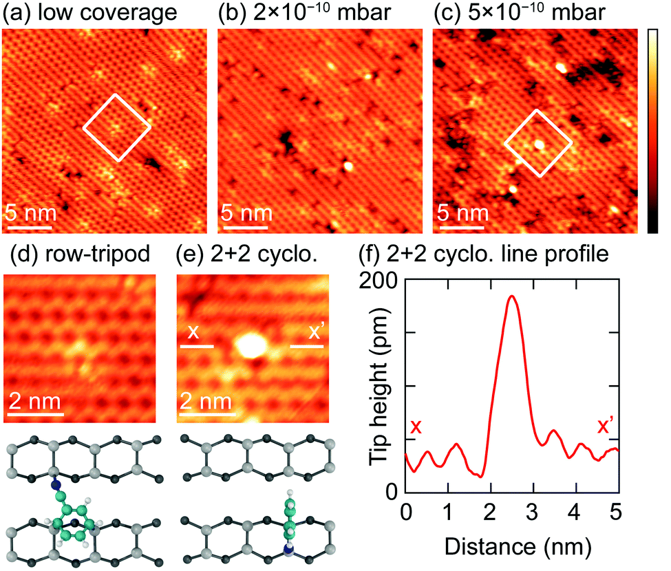 | ||
| Fig. 10 (a) Filled state topography (−2 V, 20 pA) of a low coverage of benzonitrile molecules at 77 K. Higher protrusions are seen at increased coverages, given by dosing at 2 × 10⁻¹⁰ mbar (b) and 5 × 10⁻¹⁰ mbar (c) for 600 s. (Both topographies at −2 V, 20 pA.) Insets (d) and (e) illustrate the difference in the features seen in panels (a) and (c), respectively, in more detail. Panel (f) shows a line profile across the bright feature in panel (e), taken between points x and x′. The z-range of all images is 180 pm. | ||
Discussion
The XPS, NEXAFS, and STM data that we have presented above are consistent with a prior STM/DFT report15 that when Si(001) is dosed at room temperature with benzonitrile to very sub-monolayer coverage only one adsorption feature forms. The trough-bridge structure fits well all of our data in this regime, while also being the most energetically favourable structure predicted by DFT.15 At higher benzonitrile coverages there are clear changes to the XPS and NEXAFS spectra that indicate the formation of at least one more adsorbate structure. We have shown that the 2+2 cycloaddition structure is a likely candidate structure in agreement with previous reports.16–18 Simulated NEXAFS spectra from the 2+2 cycloaddition structure are a good match to the experimental spectra, with some small allowances for thermal effects in the simulated spectra.Determining the reason underpinning this distinctive change in the surface reactivity of Si(001) to benzonitrile, from strongly favouring the trough-bridge structure at low coverage to a surface with a high proportion of 2+2 cycloaddition structures is an interesting problem in the physics and chemistry of the Si(001) surface and its interface with organic molecules. We offer here the following speculation. The trough-bridge structure has a large footprint: the adsorbate bonds to two silicon dimers in one row and to a third in the neighbouring row (Fig. 2a), thus disrupting three out of four silicon dimers in a rectangular 4 × 2 unit cell, but leaving the fourth one unreacted. Thus, as the coverage of benzonitrile adsorbates increases the probability of having three vacant clean silicon dimers necessary for forming the trough-bridge feature will decrease rapidly, while at the same time the probability for single clean dimer sites will remain relatively high. The 2+2 cycloaddition structure has only a single-dimer footprint and is thus able to form long after all the available trough-bridge sites have become saturated, and the uptake of 2+2 cycloaddition structures will continue until all remaining clean silicon dimer sites have been saturated.
Conclusions
We present NEXAFS and XPS data, with accompanying simulations, to explore the coverage dependence of the benzonitrile adsorption configuration and explain the seemingly conflicting structures reported previously in the literature. Our XPS suggests two nitrogen bonding modes, allowing us to also decompose the NEXAFS spectra into two features which we assign to the trough-bridge and 2+2 models. At very low coverages the row tripod model dominates adsorption, but as the coverage is increased the row tripod becomes sterically hindered and the fraction of the 2+2 model also increases. Low temperature scanning tunnelling microscopy supports these findings, which illustrate the utility of an approach to determining adsorption structures that combines theoretical and experimental NEXAFS.Funding
We acknowledge financial support from the Engineering and Physical Sciences Research Council (EP/H003991/1 and EP/L002140/1). OW is supported by the Australian Research Council (ARC) Centre of Excellence for Quantum Computation and Communication Technology (project number CE110001027). MS is grateful for an EPSRC Overseas Doctoral Award and HH for the support of the Leverhulme Trust.References
- S. P. Cummings, J. Savchenko and T. Ren, Coord. Chem. Rev., 2011, 255, 1587–1602 CrossRef CAS.
- Y. Wakayama and R. Hayakawa, Thin Solid Films, 2014, 554, 2–7 CrossRef CAS.
- A. Vilan and D. Cahen, Trends Biotechnol., 2002, 20, 22–29 CrossRef CAS PubMed.
- Functionalization of Semiconductor Surfaces, ed. F. Tao and S. L. Bernasek, John Wiley & Sons, 2012 Search PubMed.
- R. A. Wolkow, Annu. Rev. Phys. Chem., 1999, 50, 413–441 CrossRef CAS PubMed.
- G. P. Lopinski, D. D. Wayner and R. A. Wolkow, Nature, 2000, 406, 48–51 CrossRef CAS PubMed.
- O. Warschkow, I. Gao, S. R. Schofield, D. R. Belcher, M. W. Radny, S. A. Saraireh and P. V. Smith, Phys. Chem. Chem. Phys., 2009, 11, 2747–2759 RSC.
- O. Warschkow, D. R. Belcher, M. W. Radny, S. R. Schofield and P. V. Smith, Phys. Rev. B: Condens. Matter Mater. Phys., 2011, 84, 153302 CrossRef.
- S. R. Schofield, O. Warschkow, D. R. Belcher, K. A. Rahnejat, M. W. Radny and P. V. Smith, J. Phys. Chem. C, 2013, 117, 5736–5741 CAS.
- F. Tian and A. V. Teplyakov, Langmuir, 2013, 29, 13–28 CrossRef CAS PubMed.
- R. Miotto, M. C. Oliveira, M. M. Pinto, F. de Leon-Perez and A. C. Ferraz, Phys. Rev. B: Condens. Matter Mater. Phys., 2004, 69, 235331 CrossRef.
- F. Tao, W. S. Sim, G. Q. Xu and M. H. Qiao, J. Am. Chem. Soc., 2001, 123, 9397–9403 CrossRef CAS PubMed.
- F. Gao and A. V. Teplyakov, J. Phys. Chem. C, 2016, 120, 5539–5548 CAS.
- O. Pluchery, R. Coustel, N. Witkowski and Y. Borensztein, J. Phys. Chem. B, 2006, 110, 22635–22643 CrossRef CAS PubMed.
- D. R. Belcher, M. W. Radny, S. R. Schofield, P. V. Smith and O. Warschkow, J. Am. Chem. Soc., 2012, 134, 15312–15317 CrossRef CAS PubMed.
- F. Tao, Z. H. Wang and G. Q. Xu, J. Phys. Chem. B, 2002, 106, 3557–3563 CrossRef CAS.
- Y.-Q. Qu and K.-L. Han, J. Phys. Chem. B, 2004, 108, 8305–8310 CrossRef CAS.
- S. Rangan, J.-J. Gallet, F. Bournel, S. Kubsky, K. Le Guen, G. Dufour, F. Rochet, F. Sirotti, S. Carniato and V. Ilakovac, Phys. Rev. B: Condens. Matter Mater. Phys., 2005, 71, 165318 CrossRef.
- B. C. C. Cowie, A. Tadich and L. Thomsen, AIP Conf. Proc., 2010, 1234, 307–310 CrossRef.
- B. Watts, L. Thomsen and P. Dastoor, J. Electron Spectrosc. Relat. Phenom., 2006, 151, 105–120 CrossRef CAS.
- J. Stöhr, NEXAFS Spectroscopy, Springer, 2003 Search PubMed.
- E. Gann, C. R. McNeill, A. Tadich, B. C. C. Cowie and L. Thomsen, J. Synchrotron Radiat., 2016, 23, 374–380 CAS.
- V. Blum, R. Gehrke, F. Hanke, P. Havu, V. Havu, X. Ren, K. Reuter and M. Scheffler, Comput. Phys. Commun., 2009, 180, 2175–2196 CrossRef CAS.
- J. P. Perdew, K. Burke and M. Ernzerhof, Phys. Rev. Lett., 1996, 77, 3865–3868 CrossRef CAS PubMed.
- P. Giannozzi, S. Baroni, N. Bonini, M. Calandra, R. Car, C. Cavazzoni, D. Ceresoli, G. L. Chiarotti, M. Cococcioni, I. Dabo, A. Dal Corso, S. de Gironcoli, S. Fabris, G. Fratesi, R. Gebauer, U. Gerstmann, C. Gougoussis, A. Kokalj, M. Lazzeri, L. Martin-Samos, N. Marzari, F. Mauri, R. Mazzarello, S. Paolini, A. Pasquarello, L. Paulatto, C. Sbraccia, S. Scandolo, G. Sclauzero, A. P. Seitsonen, A. Smogunov, P. Umari and R. M. Wentzcovitch, J. Phys.: Condens. Matter, 2009, 21, 395502 CrossRef PubMed.
- C. Gougoussis, M. Calandra, A. P. Seitsonen and F. Mauri, Phys. Rev. B: Condens. Matter Mater. Phys., 2009, 80, 075102 CrossRef.
- M. Taillefumier, D. Cabaret, A. Flank and F. Mauri, Phys. Rev. B: Condens. Matter Mater. Phys., 2002, 66, 195107 CrossRef.
- P. E. Blöchl, Phys. Rev. B: Condens. Matter Mater. Phys., 1994, 50, 17953–17979 CrossRef.
- L. Triguero and L. G. M. Pettersson, Phys. Rev. B: Condens. Matter Mater. Phys., 1998, 58, 8097–8110 CrossRef CAS.
- T. Mizoguchi, I. Tanaka, S.-P. Gao and C. J. Pickard, J. Phys.: Condens. Matter, 2009, 21, 104204 CrossRef PubMed.
- G. Hähner, Chem. Soc. Rev., 2006, 35, 1244–1255 RSC.
- A. Khaliq, D. Pierucci, H. Tissot, J. J. Gallet, F. Bournel, F. Rochet, M. Silly and F. Sirotti, J. Phys. Chem. C, 2012, 116, 12680–12686 CAS.
- J. Schnadt, J. Schiessling and P. A. Brühwiler, Chem. Phys., 2005, 312, 39–45 CrossRef CAS.
- J. F. Morar, F. J. Himpsel, G. Hollinger, G. Hughes and J. L. Jordan, Phys. Rev. Lett., 1985, 54, 1960–1963 CrossRef CAS PubMed.
- P. A. Brühwiler, A. J. Maxwell, C. Puglia, A. Nilsson, S. Andersson and N. Mårtensson, Phys. Rev. Lett., 1995, 74, 614–617 CrossRef PubMed.
- T. Nakayama, K. Inamura, Y. Inoue, S. Ikeda and K. Kishi, Surf. Sci., 1987, 179, 47–58 CrossRef CAS.
- F. Tao, M. H. Qiao, Z. H. Wang and G. Q. Xu, J. Phys. Chem. B, 2003, 107, 6384–6390 CrossRef CAS.
Footnotes |
| † Electronic supplementary information (ESI) available: Supplementary methodology. See DOI: 10.1039/c6cp04328c |
| ‡ Present address: Department of Physical Sciences, The Open University, Walton Hall, Milton Keynes, MK7 6AA, UK. |
| This journal is © the Owner Societies 2016 |