
 Open Access Article
 This Open Access Article is licensed under a
 Creative Commons Attribution 3.0 Unported Licence
Illuminating solid gas storage in confined spaces – methane hydrate formation in porous model carbons†
Lars
Borchardt
*a,
Winfried
Nickel
a,
Mirian
Casco
b,
Irena
Senkovska
 a,
Volodymyr
Bon
a,
Dirk
Wallacher
c,
Nico
Grimm
c,
Simon
Krause
a and
Joaquín
Silvestre-Albero
*b
a,
Volodymyr
Bon
a,
Dirk
Wallacher
c,
Nico
Grimm
c,
Simon
Krause
a and
Joaquín
Silvestre-Albero
*b
aInstitute for Inorganic Chemistry, Technische Universität Dresden, Bergstrasse 66, 01069 Dresden, Germany. E-mail: lars.borchardt@tu-dresden.de
bLaboratorio de Materiales Avanzados, IUMA, Universidad de Alicante, Ctra. San Vicente del Raspeig-Alicante s/n, E-03690 San Vicente del Raspeig, Spain. E-mail: joaquin.silvestre@ua.es
cDepartment of Sample Environments, Helmholtz-Zentrum Berlin für Materialien und Energie, Germany
First published on 7th July 2016
Abstract
Methane hydrate nucleation and growth in porous model carbon materials illuminates the way towards the design of an optimized solid-based methane storage technology. High-pressure methane adsorption studies on pre-humidified carbons with well-defined and uniform porosity show that methane hydrate formation in confined nanospace can take place at relatively low pressures, even below 3 MPa CH4, depending on the pore size and the adsorption temperature. The methane hydrate nucleation and growth is highly promoted at temperatures below the water freezing point, due to the lower activation energy in ice vs. liquid water. The methane storage capacity via hydrate formation increases with an increase in the pore size up to an optimum value for the 25 nm pore size model-carbon, with a 173% improvement in the adsorption capacity as compared to the dry sample. Synchrotron X-ray powder diffraction measurements (SXRPD) confirm the formation of methane hydrates with a sI structure, in close agreement with natural hydrates. Furthermore, SXRPD data anticipate a certain contraction of the unit cell parameter for methane hydrates grown in small pores.
Introduction
Methane storage in the form of gas hydrate, so-called solid natural gas storage (SNG), has gained increased interest in the last few years due to the high volumetric capacity of these crystalline systems (above 180 v/v).1 This technology is inspired by nature and, more specifically, by natural gas hydrates. These structures constitute the world’s untapped natural gas reserves and are located deep-under sea and in the permafrost. Natural hydrates exhibit a cubic sI structure and are constituted by two different types of cages: (i) six large cages containing twelve pentagonal and six hexagonal faces (51262) and (ii) two small cages having twelve pentagonal faces (512), with a unit cell lattice constant of about 1.2 nm.1 Despite being thermodynamically favourable, the synthesis of artificial methane hydrates exhibits disadvantageous kinetic limitations associated with a limited solubility of methane in water and/or ice, thus limiting any possible exploitation of this technology in highly demanding sectors such as automobile industry. Although there is still an open debate,2 transportation of natural gas as hydrates could be performed at a temperature higher than that needed for natural gas liquefactions (LNG), and at a pressure lower than usually used for compressed natural gas (CNG) storage, with the associated economic and safety advantages.Recent studies performed by Casco et al. have shown that the kinetic limitations of methane hydrate growth can be overcome using high-surface area activated carbons as a host structure.3 The nano-confinement effects in the carbon cavities and the hydrophobic properties of the carbon surface constitute the philosopher’s stone for the enhancement in the nucleation and growth kinetics.3–6 This finding has been supported by similar studies on hydrophobic sand, dry water, silica gels, and hydrophobic metal–organic-frameworks (MOFs).7–10 According to studies performed on MOFs, molecular interactions at the fluid–surface enhance the gas hydrate formation yield, i.e. hydrophobic surfaces promote water–methane interactions and consequently, the hydrate formation process. Artificial methane hydrates synthesized in the presence of nanoporous solids (preferentially in the presence of hydrophobic materials) are fully reversible and exhibit a stoichiometry that mimics natural hydrates (CH4·5.75H2O, also known as sI structure).3 Concerning the importance of the nano-confinement effects taking place inside small cavities in promoting the methane hydrate nucleation and growth, the scope of this article is to rationalize the real role of the host porous structure, particularly its pore sizes, on the gas hydrate formation and dissociation process (Fig. 1). This knowledge is the key to design a proper porous system able to achieve a maximum in the methane storage capacity required for a final industrial exploitation. In order to overcome the limitations associated with conventional ill-defined activated carbons, this study aims to evaluate four model carbon materials with uniform and well-defined pore cavities.11 The combined evaluation of a purely microporous material, two mesoporous carbons and a macroporous sample may shed light into the critical role of the pore size. These four model systems were evaluated in the methane hydrate formation process at different temperatures ranging from 2 °C down to −17 °C and pressures up to 10 MPa. These systematic studies allowed to derive phase diagrams for the methane hydrate nucleation and dissociation under confined environments and to improve the overall methane storage capacity by 173% as compared to a dry material.
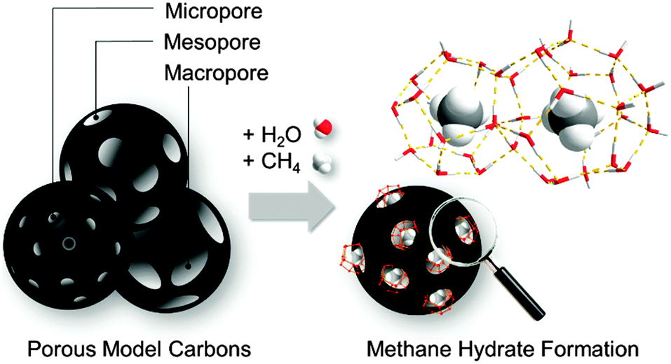 | ||
| Fig. 1 Methane hydrate formation in the confined spaces of porous model carbons covering the range from micro- to meso- and macropores. | ||
Experimental
Synthesis of model carbons
Cmicro was prepared from crystalline TiC powder (Sigma Aldrich, 95%) with a particle size <4 μm. TiC (1.0 g) was transferred into a quartz boat and placed in a horizontal tubular furnace equipped with a quartz tube. After flushing with 150 mL min−1 argon for 0.5 h the material was heated to 1000 °C with a rate of 450 K h−1. When reaching that value the gas flow was changed to a mixture of 80 mL min−1 chlorine and 70 mL min−1 argon. After 2 h of chlorination the furnace was cooled down to 600 °C under an argon flow of 150 mL min−1. At that temperature, the gas flow was changed to 80 mL min−1 hydrogen for 1 h with regard to remove chlorine adsorbed in the pores followed by cooling to room temperature under flowing argon.Cmeso-1 and Cmeso-2 were synthesized by first preparing a seed solution of 10 nm-sized silica particles. Therefore, 0.174 g of the amino acid L-arginine was dissolved in 174 g water. Afterwards 10.41 g of tetraethyl orthosilicate (TEOS) were added dropwise at 70 °C. The resulting emulsion was stirred for 24 h at 70 °C and 1000 rpm. Parts of the resulting dispersion was dried and calcined at 600 °C for 5 h. The resulting 10 nm silica nanoparticles were used as template for Cmeso-1. For Cmeso-2, 25 nm-sized silica nanoparticles have to be prepared by taking 25.96 g of the prior synthesized solution as seeds and adding 336.87 g of ethanol, 151.86 g of water, 13.16 g TEOS and 0.49 g of L-arginine at 70 °C followed by 24 h of stirring at 70 °C. Afterwards, the solvent was removed by vacuum drying and the resulting silica nanoparticles were calcinated at 600 °C for 5 h. 1 g of the silica nanoparticles were dispersed via ultrasonic sound in 10 mL of an aqueous solution containing 0.5 g of sucrose. Afterwards, 1 droplet of concentrated H2SO4 was added. The sample was put into a drying oven first at 100 °C for 6 h and subsequently at 160 °C for 3 h. Then, the sample was pyrolyzed at 900 °C (150 K h−1) under argon atmosphere for 2 h. The silica template was removed by washing with a solution of 80 mL water, 80 mL Ethanol and 80 mL 40 vol% hydrofluoric acid for 24 h. Finally, the materials were washed with excess of ethanol and dried at room temperature. Cmacro was synthesized by cutting pine wood (Pinaceae) into discs of approximately 1 g, 10 mm in diameter and 20 mm in height, cleaning them from bark, and drying at 80 °C, for 24 h in air. Afterwards the dried samples were pyrolyzed at 800 °C in argon atmosphere for 2 h.
N2 physisorption
Prior to adsorption measurements, all samples were degassed under vacuum at 150 °C for at least 5 h. N2 physisorption measurements were carried out at −196 °C on an Autosorb 1C (Quantachrome Instruments). Specific surface areas were calculated using the Multi-Point BET method (p/p0 = 0.05–0.2). Total pore volumes were determined from the amount adsorbed at p/p0 = 0.97. Pore size distributions (PSDs) were calculated from the adsorption branch using the Quenched Solid Density Functional Theory (QSDFT) method assuming slit pore geometry for Cmicro and cylindrical/spherical pore geometry for the other samples.H2O adsorption
Prior to adsorption measurements, all samples were degassed under vacuum at 150 °C for at least 5 h. Water vapor adsorption was performed at 25 °C using a Quantachrome Hydrosorb apparatus.High pressure methane adsorption
Prior to the impregnation process all samples were degassed at 150 °C for at least 5 h. Afterwards the carbons were loaded with water by placing them in a desiccator (100% humidity) for at least 3 days. Before and after loading the carbons masses were taken to calculate the water loading. High pressure methane adsorption measurements were performed between 254 and 275 K up to 100 bar using a volumetric BELSORP HP apparatus. After measurement samples were weighed again to prove no leaching of water.In situ high-pressure adsorption/powder X-ray diffraction study
Combined high pressure methane adsorption and powder X-ray diffraction experiments were conducted at KMC-2 beamline of BESSY II light source of HZB (Helmholtz-Zentrum Berlin für Materialien und Energie). A capillary-based sample cell, centered in the synchrotron beam, was connected to a BELSORP-HP gas dosing system. An alternate 180° rotation of the capillary in the beam was implemented by using a script-controlled step motor. The temperature of the sample was directly measured by Pt100 thermocouple, connected to the temperature controller. The tempering of the sample was provided by a nitrogen flow cooler N-Helix (Oxford Cryosystems). A 0.01 mm thin quartz capillary (HILGENBERG) with diameter of 0.5 mm was glued in a 1/2” VCR weld gland (SWAGELOK) and tested for the leak with helium up to 8 MPa. After that the capillary was filled with the water-loaded carbon and connected via a SWAGELOK thread to a BELSORP-HP apparatus. All in situ experiments were carried out at −9 °C. The diffraction experiments were conducted in transmission geometry in the 2θ range from 5 to 90° using monochromatic synchrotron radiation (8048 eV; λ = 1.5406 Å). The diffraction images from 2D detector were integrated using Datasqueeze 2.2.9 software. NIST material 640a was used as external standard. Before dosing methane, the pressure in the gas line was reduced to 50 kPa. The dosing of the methane occurred manually in the pressure range between 10−6 and 6 MPa with 1 MPa steps. After each dose, the pressure was corrected in order to hold the target value. After 20 minutes of equilibration, the PXRD patterns were measured.The zero shift of the instrument of +0.02659° was determined from the PXRD patterns of the NIST 640a standard material. Further this value was used in the Le Bail fit of the PXRD patterns,28 measured Cmicro and Cmeso1 materials, loaded with methane at 60 bar at −9 °C. The Le Bail fits for both PXRD patterns are shown in Fig. S2 (ESI†). The detailed information about the profile fit is given in Table S1 (ESI†).
Electron microscopy
Scanning electron microscopy (SEM) was performed using a ZEISS DSM-982 Gemini. Scanning transmission electron microscopy (STEM) was performed using a Hitachi SU8020.Results and discussion
Model carbons
Textural properties of the carbon samples selected for the study of methane hydrate formation (further denoted as Cmicro, Cmeso-1, Cmeso-2, and Cmacro) have been evaluated using N2 physisorption at −196 °C (Fig. 2 and Table 1). Sample Cmicro exhibits a Type Ia adsorption isotherm characteristic of a purely microporous carbon material with a mean pore size below 0.8 nm, i.e. below the unit cell size of the hydrate structure (a = 1.2 nm for the cubic cell of sI methane hydrate). Cmeso-1 and Cmeso-2 are mesoporous carbons prepared by a hard-templating approach, which exhibit spherical pores of 10 and 25 nm in diameter, respectively. The pore dimensions are large enough to allocate methane hydrate crystallites that are several unit cells in size. The uniform pore size is validated by the type IV N2 isotherm with a H1 hysteresis (Fig. 2), and also visualized by SEM and STEM images (Fig. 3). Cmacro is a macroporous material with cellular pores of approximately 10 μm (Fig. 3) and a non-significant nitrogen adsorption capacity. Further characterization of the model materials are provided in the ESI.† | ||
| Fig. 2 Nitrogen adsorption/desorption isotherms for the different model carbons at −196 °C; inset – pore size distribution (PSD) obtained after application of the QSDFT model (slit-shape adsorption model for Cmicro and cylindrical/spherical adsorption model for Cmeso-1 and Cmeso-2). | ||
| Sample | Mean pore sizee/nm | Surface areac/m2 g−1 | N2 pore volumea/cm3 g−1 | N2 micropore volume/cm3 g−1 | H2O pore volume/cm3 g−1 | Total water uptake gH2O/gcarbond | Particle size |
|---|---|---|---|---|---|---|---|
| a Analyzed from N2-physisorption for pores smaller 90 nm. b Analyzed by SEM imaging. c Multipoint BET surface area calculate for 0.05 < p/p0 < 0.2. d Water vapor loading at 100% humidity for 3 days. e Mean pore size derived from Fig. 2B – QSDFT kernel, adsorption branch. f From geometrical calculation assuming a carbon density of 2.3 g cm−3 and a He-pycnometric density of 0.346 g cm−3. g Pores cannot be filled entirely at the maximum water pressure of p/p0 = 0.98 due to the large pore size and the high hydrophobicity. Measurement at higher p/p0 would result in water condensation inside the sample cell. | |||||||
| Cmicro | 0.8 | 1527 | 0.8 | 0.60 | 0.5 | 0.49 | 1–5 μm |
| Cmeso-1 | 10 | 1112 | 1.3 | 0.14 | 0.3g | 2.35 | 1–5 μm |
| Cmeso-2 | 25 | 993 | 2.6 (3.3) | 0.18 | 0.25g | 2.46 | 1–5 μm |
| Cmacro | >10![[thin space (1/6-em)]](https://www.rsc.org/images/entities/char_2009.gif) 000b 000b |
18 | <0.1 (5.5)f | <0.01 | 0.13 | 0.29 | ∼5 mm |
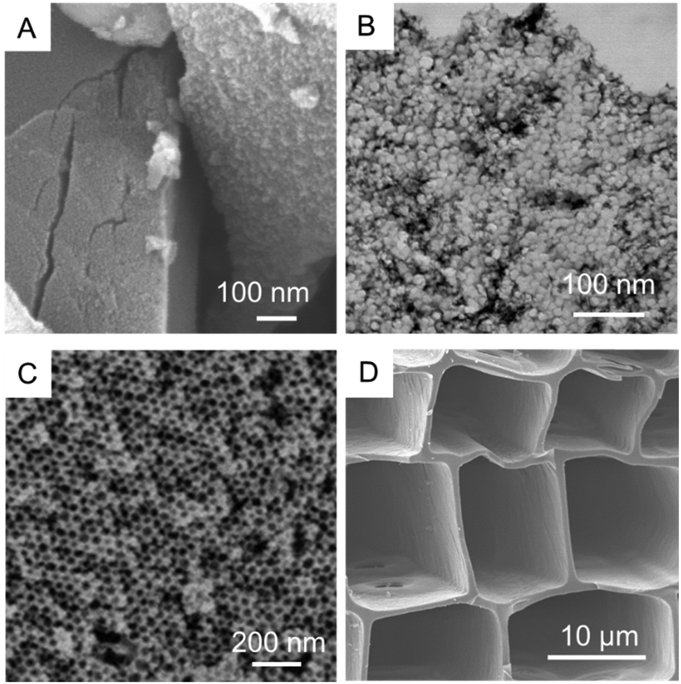 | ||
| Fig. 3 SEM and STEM images of the four model carbons: (A) Cmicro, (B) Cmeso-1, (C) Cmeso-2 and (D) Cmacro. | ||
To track the saturation uptake water vapours adsorption isotherms at 25 °C were measured before performing the methane adsorption experiments in the pre-humidified samples (Fig. S1, ESI†). All samples exhibit the characteristic behavior for hydrophobic carbons with a very limited adsorption uptake below p/p0 ≈ 0.3. Above this relative pressure there is a sudden rise in the water amount adsorbed for all samples associated with the well-known water-clustering mechanism, as proposed by Dubinin et al.12 Water adsorption isotherms of all samples exhibit an explicit hysteresis loop at high relative pressures associated with the metastable water adsorption process.13 It is important to highlight that sample Cmicro exhibits nearly a two-fold increase in the water adsorption capacity compared to the mesoporous carbons (Cmeso-1 and Cmeso-2), that is not reflected in the N2 total pore volume (Table 1). This observation anticipates the preferential water condensation in micropores and small mesopores, in close agreement with previous studies.13 Indeed, the pore volume calculated from water adsorption isotherm for Cmicro at p/p0 ≈ 0.98 is closer to the micropore volume rather than to the total pore volume estimated from nitrogen physisorption experiment. X-ray and neutron scattering measurement by Iiyama have anticipated that the structure of water adsorbed in hydrophobic carbon narrow micropores must be rather similar to a solid-like structure even at 25 °C, with the corresponding effect in the methane hydrate formation process.14
Methane hydrate formation in confined space
After pre-humidification (saturation at atmospheric pressure), model carbons were tested in the methane adsorption process at pressures up to 10 MPa. Concerning the microporous sample (Fig. 4A), methane adsorption isotherms show an initial uptake in the low-pressure region (up to 1.5–2.0 MPa) that perfectly fits all temperatures evaluated (except that at −17 °C). This initial uptake at very low pressures must be associated to methane physisorption processes occurring in cavities not participating in the water adsorption process or that are not fully occupied with water. Above this initial region, there is a progressive increase in the amount of methane adsorbed up to a given threshold pressure, when a sudden jump in the adsorption capacity can be clearly appreciated. The minimum pressure for the vertical jump strongly depends on the adsorption temperature, i.e., it is shifted to lower pressures with a decrease in the adsorption temperature. As the phase equilibrium pressure of CH4 hydrate decreases with decreasing temperature, at low adsorption temperatures (−9 °C and −17 °C) only a single deviation can be appreciated below 1.5 MPa. These changes observed in the slope of the methane adsorption isotherm upon a certain pressure, preferentially at temperatures near the water freezing point, could be attributed to a different methane hydrate-growing environment.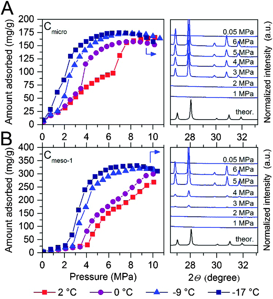 | ||
| Fig. 4 Methane adsorption isotherms of water-loaded (A) Cmicro (mean pore size 0.8 nm) and (B) Cmeso-1 (mean pore size 10 nm) samples (saturated) at different adsorption temperatures and up to 10 MPa. The right side of the graph correspond to the synchrotron X-ray diffraction pattern (λ = 0.15406 nm) for these two samples at −9 °C and ranging methane pressure. For the sake of clearness, the desorption branches are not displayed (see ESI† for full isotherms). | ||
High-pressure methane adsorption measurements have been complemented by in situ synchrotron X-ray powder diffraction (SXRPD) measurements. These measurements were performed at HZB (Helmholtz-Zentrum Berlin) using capillary-based instrumentation, commissioned at KMC-2 beamline (see ESI† for more details). As it can be seen in Fig. 4, at −9 °C and above 3 MPa, the XRD pattern exhibits characteristic diffraction peaks at 26.9, 27.9, 29.8 and 30.8° 2θ corresponding to the sI structure of the methane hydrate (for full XRD pattern see Fig. S2, ESI†). Interestingly, application of the Scherrer equation to the FWHM of the most intensive (321) reflection at 2θ = 27.9° gives an average crystallite size of ca. 70–85 nm. Taking into account that this is a purely microporous sample (dp = 0.8 nm), the large crystal size obtained from SXRPD must be exclusively due to methane hydrate located at the external surface or in the interparticle space. This is in accordance to Falenty et al.15 describing that the nucleation of methane hydrate takes place first in the external water layers at the pore mouth and the subsequent growing process proceeds towards the inside cavity. Simultaneously however, the lower water density in the hydrate gives rise to a concomitant outward diffusion of pore water molecules or already formed hydrate nuclei (iceberg-like model) to the exterior surface to grow new hydrate crystals. Hence, always two growing mechanism coexist with opposing spatial direction.
“Methane hydrate species” that are located in the micropores cannot be detected by synchrotron X-ray diffraction due to their size or amorphous character. Indeed, the readers should be aware that these species cannot be considered as typical hydrate structure (and are therefore in the following denoted as methane hydrated species), since the sI lattice cell (1.2 nm) is too large for these pores. However, two points strongly arguments for the formation of methane hydrated species inside micropores, with a denser structure as compared to purely physisorbed methane. Firstly, the increased uptake of methane for the wet carbon as compared to the dry carbon (Table 2) and secondly, the unit cell parameters of methane hydrate grown on microporous carbons is significantly decreased as compared to bulk methane hydrate. The latter will be explained more deeply at the end of this section.
To gain deeper understanding of the porous structure in sample Cmicro, argon physisorption was performed at −186 °C since it estimates the pore size distribution more accurate as compared to N2.16 As shown in Fig. S3 (ESI†), Cmicro exhibits two well-defined pore cavities in the microporous range, one centered at 0.48 nm (0.16 cm3 g−1) and another centered at 0.76 nm (0.46 cm3 g−1). We can assume that at 2 °C the small cavities with a high adsorption potential must be filled with water with a different aggregation state (close to a solid-like structure), as compared to the larger cavities, where water must be preferentially in liquid-like phase.14 Recently Oschatz et al. obtained corroborative results for Cmicro using high pressure Xe NMR spectroscopy.17 Taking into account that the hydrate formation is an interfacial phenomenon, the growth of methane hydrate always proceed from the outside to the inside (perpendicular to the interface).15,18–20 Thus, ice-like water in the small cavities must be blocked by liquid-like water in larger cavities. Consequently, at 2 °C the initial hydrate formation (above 1.4 MPa) must take place preferentially in wider micropores, nucleation being restricted (higher activation energy) in liquid-like phase, whereas the sudden jump observed at 6.4 MPa could be attributed to the methane hydrate formation in the inner cavities with a different water-structure environment (maybe solid-like ice in the uniform 0.48 nm cavities). This observation will be in close agreement with the threshold pressure for bulk methane hydrates at around 3–4 MPa at 2 °C and the larger kinetic limitations for nucleation and growth in inner cavities (methane must diffuse/permeate through external hydrate crystals to reach inner cavities).3 Below the water-freezing point, pre-adsorbed water, even in wide micropores and/or small mesopores, gets the solid-like structure. Under such conditions, methane hydrate growth is clearly speeded-up even in narrow cavities,15e.g. at −17 °C the steep increase in the uptake indicative for the methane hydrate growth is already observed at pressures below 2 MPa and completed at 5–6 MPa. This behavior cannot be explained by diffusion although one could expect that the lower density of ice as compared to liquid water allows for better diffusion of methane. This is not the case since the diffusion rate of methane in ice (2.9 × 10⁻¹⁴ m2 s−1 at 268.15 K) is one order of magnitude lower than that of methane in water (1.7 × 10⁻¹³ m2 s−1 at 272.65 K).21 The reason can rather be found in the activation energy required for the growth of methane hydrate. This energy becomes larger with an increasing temperature.15 Moreover, molecular simulations have anticipated an enhanced nucleation and growth of gas hydrates at the interface of hexagonal ice due to the formation of defective structures, particularly coupled 5–8 ring defects, not present in liquid water.22 However, some additional shifting due to the presence of subcooling conditions cannot be ruled out (see ESI†).
The scenario changes completely for a carbon material with larger cavities. As shown in Fig. 4B, independently of the adsorption temperature, water saturated Cmeso-1 sample exhibits serious blocking effects by pre-adsorbed water. For instance, at 2 °C there is neither hydrate formation nor methane physisorption below 4.1 MPa observed. Above this threshold pressure, there is a continuous increase in the amount of methane adsorbed up to a final value close to 267 mg g−1. This behaviour can be attributed to the described kinetic limitations in liquid-like phase, and the associated induction period for the formation of the initial hydrate nucleus.20,23 Similar to the microporous carbon, a decrease in the adsorption temperature below the freezing point gives rise to a decrease in the threshold pressure for methane hydrate formation down to 2.1 MPa at −17 °C, and a steeper increase in the nucleation process (lower activation energy under ice-like conditions compared to liquid-like conditions). The presence of the sI methane hydrate structure in sample Cmeso-1 has also been confirmed using synchrotron X-ray powder diffraction (Fig. 4B). At this point it is interesting to highlight that the final methane adsorption capacity in both pre-humidified samples (Cmicro and Cmeso-1) is rather independent of the adsorption temperature, thus suggesting a similar water-to-hydrate yield, irrespective of the adsorption temperature. Last but not least, the stoichiometry of the synthesized gas hydrates has been estimated from the total amount of water pre-adsorbed at saturation (Table 1) and the total amount of methane adsorbed at 10 MPa. Sample Cmeso-1 with large cavities is able to host several unit cells of methane hydrate gives a stoichiometry value of 1CH4·6.3H2O, which is very close to the stoichiometry of natural hydrates (1CH4·5.75H2O). On the contrary, sample Cmicro exhibits composition close to 1CH4·2.5H2O. There are two possible explanations for this founding: either there is a large excess of methane non-participating in the hydrate formation process, which can be attributed to the presence of a high amount of physisorbed methane or, “methane hydrated species” are formed in non-stoichiometric composition in the restricted space of the small cavities, which are too small to host a sI unit cell.3
To end up, the unit cell parameters of the methane hydrate formed in the samples Cmicro and Cmeso-1 have been estimated from the corresponding SPXRD patterns measured at −9 °C at 6 MPa after a multiphase profile refinement (ESI,† Fig. S2). Obtained from the Le Bail fit, the unit cell parameters of methane hydrate, formed in the cavities of Cmicro and Cmeso-1 are 11.9543(6) Å and 11.9604(4) Å, respectively (ESI,† Table S1). At this point it is important to highlight that these cell parameters are significantly smaller than that of a bulk methane hydrate, which was comprehensively investigated by Kuhs and co-workers, reporting the unit cell parameter of 11.9760(6) Å for the bulk methane hydrate at 265.1 K.18 The decrease of the unit cell parameters is 0.0217 Å and 0.0156 Å, for Cmicro and Cmeso-1, respectively. This verifies the effect of confinement in micro- and mesopores and evidences that even when those methane hydrate species are located at the external surface (and only these are detectable by SPXRD) they have started growing from a confined environment, i.e. pore cavity or pore mouth.
Pore size dependency on methane hydrate storage
As described above, the adsorption temperature and the size of the cavity are critical parameters defining the nucleation and growth of the confined hydrates (threshold pressure and extend of the hydrate formation process). To identify the optimum pore size, high-pressure methane adsorption measurements were performed at −9 °C in different water-saturated samples. Fig. 5 shows the adsorption/desorption curves up to 10 MPa, including the bulk experiment in the absence of carbon.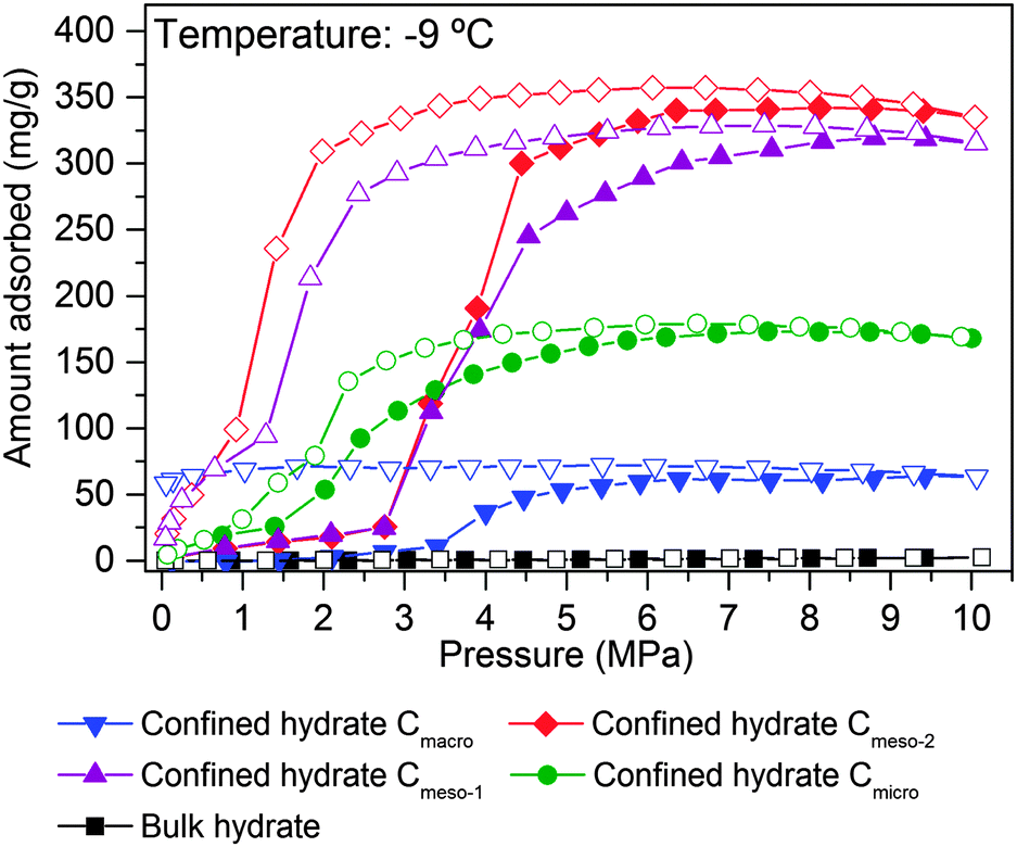 | ||
| Fig. 5 Methane adsorption isotherm at −9 °C for the different pre-humidified (saturated samples) model carbons: Cmicro (0.8 nm), Cmeso-1 (10 nm), Cmeso-2 (25 nm) and Cmacro (10000 nm), up to 10 MPa. Bulk water is included for the sake of comparison. | ||
As shown in Fig. 5, the amount of methane adsorbed in pre-humidified carbons strongly depends on the mean pore size. The total amount of methane adsorbed via hydrate formation increases with the increasing pore size up to an optimum for mesoporous carbons (Cmeso-2 ≈ Cmeso-1 > Cmicro > Cmacro). Despite the differences in the mean pore size, Cmeso-2 and Cmeso-1 exhibit a similar adsorption performance, in terms of total amount adsorbed and nucleation threshold pressure. Larger cavities (in the macroporous range) became disadvantageous for the methane hydrate formation process probably due to the low water-adsorption capacity of these samples at saturation and to the low water-to-hydrate yield under bulk-like conditions (Tables 1 and 2). At this point it is important to highlight that, independently of the mean pore size, all isotherms exhibit a pronounced hysteresis loop unambiguously associated with the metastable hydrate formation process in confined cavities.23 Interestingly, the methane adsorption capacity of ice at −9 °C, in the absence of carbon, is rather zero up to 10 MPa, within the timescale and the equilibrium conditions used in this experimental setup (pressure change below 2 kPa for at least 1800 s). This confirms the promoting effect of carbon cavities in this technology. To further confirm the positive influence of mesocavities, the total amount of methane adsorbed for the different samples at high pressure before and after water pre-adsorption are compared in Table 2. Under dry conditions (i.e. absence of water) the methane adsorption capacity is very high for samples containing micropores and/or medium-size mesopores (Cmicro and Cmeso-1), because of higher adsorption potential and packing density in narrow cavities.24 However, the scenario changes completely after water pre-adsorption. Under wet conditions the methane adsorption capacity increases up to 341 mg g−1 in the Cmeso-2 sample. Compared to the dry carbons, the improvement for sample Cmeso-2 is as high as 173%.
These results constitute the first experimental evidence about the real effect of the mean pore size in the hydrate formation process, and provide information about the proper pore size range to achieve an optimum in the methane adsorption capacity via gas hydrate formation. Neither purely microporous carbons with pore size smaller than the hydrate unit cell, nor macroporous samples are appropriate for this technology. Carbons with pores in the mesoporous range (around 30 nm) are able to allocate an optimum number of hydrate nanocrystals, with a stoichiometry similar to that of natural hydrates, but fully reversible, with fast kinetics (within minutes; Fig. S4, ESI†) and with optimum in the final amount adsorbed.
Phase diagrams of methane hydrate formation in confined space
To end up, the phase equilibria for confined methane hydrates has been estimated at different pressures and temperatures. These values have been compared with those reported in the literature for the bulk system (CH4 + water).10,18,21,25 The phase diagrams have been constructed using the nucleation (Fig. 6A) and dissociation (Fig. 6B) pressures for the confined hydrates, these values being obtained from the adsorption and desorption branches in the high pressure methane adsorption isotherms under equilibrium conditions (i.e., the adsorption system considers that equilibrium has been reached when the pressure change in the manifold is below 2 kPa within a timeframe of 1800 s).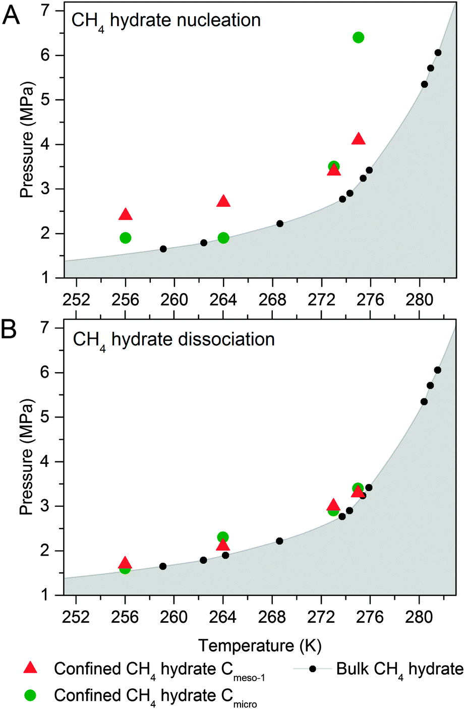 | ||
| Fig. 6 Phase diagram for methane hydrate (A) nucleation and (B) dissociation in confined nanospace. Bulk hydrate data have been included for the sake of comparison.1 | ||
As can be seen in Fig. 6A, nucleation of confined hydrates is shifted to higher pressures as compared to the bulk phase, and this effect is more pronounced for the 10 nm pore size carbon (except Cmicro sample at 2 °C). This observation is in close agreement with the slow methane hydrate nucleation and growth process (metastable conditions), preferentially when water is in liquid-like phase, i.e. for sample Cmeso-1 and Cmicro above 0 °C. After an initial nucleation on the external ice/water surface, the formation process is controlled by the permeation rate of methane molecules migrating to the core through the thickening hydrate layer and the concomitant outward migration of water molecules/hydrate nucleus to the external surface. On the contrary, Fig. 6B shows that the pressure of methane hydrate dissociation in confined nanospace is very similar for all investigated carbons, independently of the mean pore size of the host structure, and very similar to the thermodynamic data. Apparently, the dissociation is in equilibrium conditions. However, the threshold pressure for the dissociation of the confined hydrates is slightly above that of the bulk system, irrespective of the adsorption temperature evaluated and the mean pore size, i.e. the dissociation in the confined nanospace is slightly promoted compared to the bulk system. This observation can be attributed to the geometric change of water activity in the confined nanospace as described by Handa et al.10 A similar behaviour was observed for gas hydrates confined in metal–organic-framework MIL-53(Al)26 and porous glasses.27
Conclusions
In summary, phase equilibria results show that methane hydrate dissociation in the confined nanospace of model carbon materials is slightly promoted compared to the bulk system, independently of the mean pore size. The lower stability of these confined crystals is associated with their small crystal size because of the restricted growing environment and the larger water activity. On the other hand, the nucleation is inhibited compared to the bulk phase due to the metastability of the nucleation process in confined nanospace, mainly when water is in the liquid-like phase.23 For water in a solid-like state (below the water freezing point in narrow micropores), nucleation is highly promoted due to the accumulation of methane molecules at the ice surface, and the induced promotion of defective structures (the so-called IPN mechanism: induce-promote-nucleate).22,28 From these results it is clear that surface properties and mean pore size does not affect the dissociation equilibria but rather the nucleation. Whereas larger cavities containing pre-adsorbed water in liquid-like state require higher pressures to surpass the large inductions periods associated with large water droplets (metastable hydrate nucleation),9 smaller cavities with pre-adsorbed solid-like water or thin water films in the exterior of the carbon grains or in large cavities exhibit a promoting effect compared to the bulk system, i.e. they exhibit faster kinetics due to the shorter or null induction period (initial clustering process to form partial hydrates and the formation of a critical cluster size), unless these cavities are in the inner porosity with limited accessibility. With this respect a microporous carbon can initiate methane hydrate growth even at pressures below 2 MPa, which is much lower than in artificial bulk hydrate. However, a proper carbon material for the gas hydrate storage technology requires cavities in the mesoporous range, i.e. a porous carbon with well-defined 25 nm pores improves the methane storage capacity by 173% as compared to the dry material. In each case the pore size influences the unit cell parameters of methane hydrate that is confined in the restricting environment of a nanoporous carbon. In order to reach an optimum performance for methane storage, a compromise between proper kinetics and proper stoichiometry is necessary.Acknowledgements
L. B. gratefully acknowledges the Federal Ministry of Education and Research (Bundesministerium für Bildung und Forschung, BMBF) for support of the Mechanocarb project (award number 03SF0498). J. S. A. acknowledges financial support from MINECO (project MAT-2013-45008-p) and Generalitat Valenciana (PROMETEOII/2014/004). V. B. thanks the Federal Ministry of Education and Research (Bundesministerium für Bildung und Forschung, BMBF) for financial support (project No. 05K13OD3). The authors thank Felix Hippauf for graphical support with Fig. 1 and the HZB for the allocation of synchrotron radiation beamtime at KMC-2 beamline.Notes and references
- E. Dendy Sloan, Jr. and C. Koh, Clathrate Hydrates of Natural Gases, 3rd edn, CRC Press, New York, 2007 Search PubMed.
- G. Rehder, R. Eckl, M. Elfger, A. Falenty, R. Hamann, N. Kähler, W. F. Kuhs, H. Osterkamp and C. Windmaier, Energies, 2012, 5, 2499 CrossRef CAS.
- M. A. Casco, J. Silvestre-Albero, A. J. Ramírez-Cuesta, F. M. Rey, J. L. Jordá, A. Bansode, A. Urakawa, I. Peral, M. Martínez-Escandell, K. Kaneko and F. Rodríguez-Reinoso, Nat. Commun., 2015, 6, 6432 CrossRef CAS PubMed.
- A. Perrin, A. Celzard, J. F. Marêché and G. Furdin, Energy Fuels, 2003, 17, 1283 CrossRef CAS.
- J. Liu, Y. Zhou, Y. Sun, W. Su and L. Zhou, Carbon, 2011, 49, 3731 CrossRef CAS.
- A. Celzard and J. F. Marêché, Fuel, 2006, 85, 957 CrossRef CAS.
- W. Wang, C. L. Bray, D. J. Adams and A. I. Cooper, J. Am. Chem. Soc., 2008, 130, 11608 CrossRef CAS PubMed.
- J. Wang, R. Wang and R.-H. Yoon, J. Chem. Eng. Data, 2015, 60, 383 CrossRef CAS.
- M. E. Casco, F. Rey, J. L. Jordá, S. Rudic, F. Fauth, M. Martínez-Escandell, F. Rodríguez-Reinoso, E. V. Ramos-Fernández and J. Silvestre-Albero, Chem. Sci., 2016, 7, 3658 RSC.
- P. Y. Handa and D. Stupin, J. Phys. Chem., 1992, 96, 8599 CrossRef.
- L. Borchardt, M. Oschatz and S. Kaskel, Mater. Horiz., 2014, 1, 157 RSC.
- M. M. Dubinin, E. D. Zawerina and V. V. Serpinsky, J. Chem. Soc., 1955, 1760 RSC.
- M. Nakamura, T. Ohba, P. Branton, H. Kanoh and K. Kaneko, Carbon, 2010, 48, 305 CrossRef CAS.
- T. Iiyama, K. Nishikawa, T. Otowa and K. Kaneko, J. Phys. Chem., 1995, 99, 10075 CrossRef CAS.
- A. Falenty, A. N. Salamatin and W. F. Kuhs, J. Phys. Chem. C, 2013, 117, 8443 CAS.
- J. Silvestre-Albero, A. Silvestre-Albero, F. Rodríguez-Reinoso and M. Thommes, Carbon, 2012, 50, 3128 CrossRef CAS.
- M. Oschatz, H. C. Hoffmann, J. Pallmann, J. Schaber, L. Borchardt, W. Nickel, I. Senkovska, S. Rico-Francés, J. Silvestre-Albero, S. Kaskel and E. Brunner, Chem. Mater., 2015, 26, 3280 CrossRef.
- T. C. Hansen, A. Falenty and W. F. Kuhs, J. Chem. Phys., 2016, 144, 054301 CrossRef CAS PubMed.
- Y. Makogan, Hydrates of Natural Gases, Geoexplorers Associates Inc., Denver, 1978, Translated from Russian by W.J. Cieslewicz Search PubMed.
- A. Vysniauskas and P. R. Bishnoi, Chem. Eng. Sci., 1983, 38, 1061 CrossRef CAS.
- T. Komai, S.-P. Kang, J.-H. Yoon, Y. Yamamoto, T. Kawamura and M. Ohtake, J. Phys. Chem. B, 2004, 108, 8062 CrossRef CAS.
- P. Piezadeh and P. G. Kusalik, J. Am. Chem. Soc., 2013, 135, 7278 CrossRef PubMed.
- V. Natarajan, P. R. Bishnoi and N. Kalogerakis, Chem. Eng. Sci., 1994, 49, 2075 CrossRef CAS.
- F. Rodríguez-Reinoso, Y. Nakagawa, J. Silvestre-Albero, J. M. Juarez-Galán and M. Molina-Sabio, Microporous Mesoporous Mater., 2008, 115, 603 CrossRef.
- S. Takeya, H. Fujihisa, Y. Gotoh, V. Istomin, E. Chuvilin, H. Sakagami and A. Hachikubo, J. Phys. Chem. C, 2013, 117, 7081 CAS.
- D. Kim, Y.-H. Ahn and H. Lee, J. Chem. Eng. Data, 2015, 60, 2178 CrossRef CAS.
- T. Uchida, T. Ebinuma and T. Ishizaki, J. Phys. Chem. B, 1999, 103, 3659 CrossRef CAS.
- M. Muro, M. Harada, T. Hasegawa and T. Okada, J. Phys. Chem. C, 2012, 116, 13296 CAS.
Footnote |
| † Electronic supplementary information (ESI) available. See DOI: 10.1039/c6cp03993f |
| This journal is © the Owner Societies 2016 |