
 Open Access Article
 This Open Access Article is licensed under a Creative Commons Attribution-Non Commercial 3.0 Unported Licence
Cation–cation and anion–anion complexes stabilized by halogen bonds†
David
Quiñonero
*a,
Ibon
Alkorta
*b and
José
Elguero
b
aDepartament de Química, Universitat de les Illes Balears, Crta. de Valldemossa km 7.5, 07122 Palma de Mallorca, Spain. E-mail: david.quinonero@uib.es
bInstituto de Química Médica (CSIC), Juan de la Cierva, 3, 28006 Madrid, Spain. E-mail: ibon@iqm.csic.es
First published on 9th September 2016
Abstract
Stable minima showing halogen bonds between charged molecules with the same sign have been explored by means of theoretical calculations. The dissociation transition states and their corresponding barriers have also been characterized. In all cases, the results indicate that the complexes are thermodynamically unstable but kinetically stable with respect to the isolated monomers in gas phase. A corrected binding energy profile by removing the charge–charge repulsion of the monomers shows a profile similar to the one observed for the dissociation of analogous neutral systems. The nature of the interaction in the minima and TSs has been analyzed using the symmetry adapted perturbation theory (SAPT) method. The results indicate the presence of local favorable electrostatic interactions in the minima that vanish in the TSs. Natural bond orbital (NBO) and “atoms-in-molecules” (AIM) theories were used to analyze the complexes, obtaining good correlations between Laplacian and electron density values with both bond distances and charge-transfer energy contributions E(2). The largest E(2) orbital interaction energies for cation–cation and anion–anion complexes are 561.2 and 197.9 kJ mol−1, respectively.
Introduction
The Coulombic energy is the dominant term in the interaction between charged systems. In the case of systems with the same charge, it is repulsive. Thus, for a long time it has been assumed that it is not possible to find minima between molecules with the same charge in gas phase. However, several recent articles have reported minima structures in hydrogen bonded systems.1–8 The analysis of such structures indicates that attractive electrostatic contributions between the groups involved in the HB interaction are the responsible for the presence of such minima.3,5,8It is commonly accepted that halogen atoms in haloorganics interact favorably by working as electron donor sites. For instance, the ability of halogen atoms to act as hydrogen bond acceptors is well known. However, the electron density in halogen atoms is anisotropically distributed,9–11 showing a region of high electron density that forms a belt orthogonal to the covalent bond, and a region of low electron density that generates a cap of depleted electron density on the elongation of the covalent bond capable of forming attractive interactions with electron-rich sites. Consequently, a region of positive electrostatic potential along the C–X covalent bond develops on the outermost portion of the halogen surface. This positive region has been denoted as a σ-hole,12 which is surrounded by a belt of negative electrostatic potential. Thus, according to IUPAC,13 “A halogen bond occurs when there is evidence of a net attractive interaction between an electrophilic region associated with a halogen atom in a molecular entity and a nucleophilic region in another, or the same, molecular entity.” However, a positive σ-hole is not a necessary prerequisite for a molecule to participate in a halogen bond (XB) as a halogen donor. In this regard, it was shown that an XB complex of CH3Cl with formaldehyde has a binding energy of 4.9 kJ mol−1 despite a negative σ-hole.14
Halogen bonding interactions have a wide range of applications. For instance, XB offers a new method for understanding the recognition mechanism of chemical and biological molecules,15–20 attracts great interest in drug design,21–23 and has potential applications in organocatalysis,24–28 chemical sensing and molecular recognition.29–34 Various useful crystal materials can be designed using XB including temperature-sensitive, magnetic, or optically crystalline materials.35–44 XB has also a vast potential in the design of soft materials such as liquid crystals,45–48 polymers,38,49 and gels.50
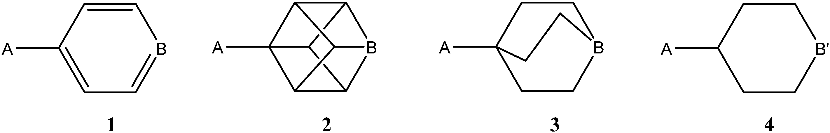
In the present article, the possibility of finding minima in gas phase for halogen bonded systems with the same sign has been explored in both cation–cation and anion–anion clusters. In addition, the solvent effect on the stability of the clusters has been considered. One of the molecules involved in the interactions is based on one of the four scaffolds indicated in Scheme 1. These scaffolds were chosen because despite having very similar dimensions between the A and B/B′ groups, one is aromatic and the rest are aliphatic with different characteristics. In the case of the cationic systems, A = NH3+ and B = N, and in the anionic systems A = CO2−, B = C–X, and B′ = N–X, with X = F, Cl, Br and I. From now on, each molecule will be identified with the number shown in Scheme 1 and the substituents in A and B/B′ positions, for instance 1[NH3+,N].
 | ||
| Scheme 1 Common scaffold of one of the molecules involved in the interaction. | ||
While this article was under preparation, a computational study of halogen bonding interaction in anion–anion complexes in models of condense media has been published.51
Computational methods
The geometry of the systems has been optimized at the M06-2x/aug-cc-pVTZ computational level.52,53 Frequency calculations at the same level have been carried out to confirm that the stationary points obtained correspond to energy minima or true transition states. Binding energies were obtained as the difference between the energy of the complex and the energies of the optimized isolated monomers. The dissociation path of the complexes has been explored by increasing the distance between the two molecules by 0.1 Å in each step up to 2.0 Å, re-optimizing the rest of the parameters. In addition, the distance was further increased to 5.0 Å in steps of 0.5 Å. To visualize the energy minimum, the intermolecular distance was decreased by 0.3 Å in three steps of 0.1 Å. The potential error of the BSSE has been considered for some selected cases at the same level with and without correction for the basis set superposition error (BSSE) using the Boys–Bernardi counterpoise technique.54 The geometry optimizations described herein were carried out by using Gaussian09 and Molpro programs.55,56The effect of the solvent on our systems has been taken into account by means of the polarizable continuum model (PCM)57 using the parameter for water as implemented in the Gaussian-09 program.
The bonding characteristics were analyzed by means of the atoms-in-molecules (AIM) theory.58,59 For this purpose, we have located the most relevant bond critical points (BCPs), and evaluated the electron density at each of them, with the facilities of AIMALL programs.60 All the interactions were characterized by the formation of a BCP between the atoms involved that are connected by the corresponding bond paths.
The natural bond orbital (NBO) method61 has been employed to evaluate atomic charges using the NBO-3.1 program,62 included within the Gaussian-09 program, and to analyze charge-transfer interactions between occupied and empty orbitals.
The SAPT (symmetry adapted perturbation theory) method allows for the decomposition of the interaction energy into different terms related to physically well-defined components, such as those arising from electrostatic, exchange, induction, and dispersion terms. The interaction energy can be expressed within the framework of the SAPT method as:
| Eint = E(1)el + E(1)exch + E(2)i + E(2)D | (1) |
The density fitting DFT-SAPT (DF-DFT-SAPT) formulation has been used to investigate interaction energies. In this approach, the energies of interacting monomers are expressed in terms of orbital energies obtained from Kohn–Sham density functional theory. In addition to the terms listed in eqn (1), a Hartree–Fock correction term δHF, which takes into account higher-order induction and exchange corrections, has been included. This is why the δHF term is usually summed up with the induction energy. The DF-DFT-SAPT calculations have been performed using the PBE0/aug-cc-pVTZ/aug-cc-pVTZ-PP computational method. As an auxiliary fitting basis set the JK-fitting basis of Weigend was employed. The cc-pVQZ JK-fitting basis was used for all atoms. For the intermolecular correlation terms, i.e., the dispersion and exchange-dispersion terms, the related aug-cc-pVTZ MP2-fitting basis of Weigend, Köhn, and Hättig was employed. All SAPT calculations have been carried out using the MOLPRO program without computing ED.
Results and discussions
As a preliminary study, for comparison purposes, the electronic characteristics of the XB donors have been studied, by computing their molecular electrostatic potentials, ESPs (Fig. 1) on the van der Waals surface.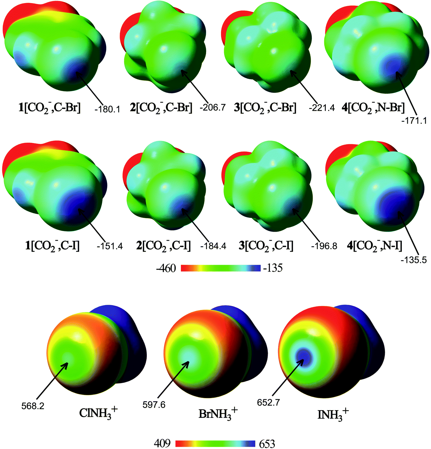 | ||
| Fig. 1 Molecular electrostatic potential (ESP) on the 0.001 a.u. electron density isosurface of halogen bond donor ions. The ESP energy values associated with the σ-hole are indicated. Energies are given in kJ mol−1. | ||
From the analysis of the ESPs, several conclusions can be drawn. All molecules exhibit regions of maxima of electrostatic potential energies around the halogen atom along the extension of the C/N–X bonds, associated with the halogen σ-hole. In fact, the N–X σ-hole is larger than the corresponding C–X σ-hole in the anionic molecules. In addition, the σ-hole becomes deeper with the halogen size. Thus, the σ-hole in iodine derivatives has less negative (or more positive) electrostatic potentials than the rest of the halogen compounds, with 4[CO2−,N–I] and INH3+ being the anion and the cation with less negative and more positive ESP values (−135.5 and 652.7 kJ mol−1, respectively). These differences come from the increasing polarizability and decreasing electronegativity when going from lighter to heavier halogens. Therefore, from the electrostatic point of view, the most favorable anion–anion complex would be formed with 4[CO2−,N–I], whereas the most favorable cation–cation complex would be that where INH3+ is involved. However, it should be taken into account that while in the isolated XB donor anions the halogen σ-hole electrostatic potential is large and negative, as soon as the molecule begins to interact with the halide anion, the electron density of each component is polarized by the electric field of the other, and a less negative (or even positive) σ-hole on the halogen would be expected.
Geometry and energy in the minima
The cation–cation complexes correspond to the association of three nitrogen bases 1–3[NH3+,N] with halogen–ammonium cations (XNH3+, X = Cl, Br, and I). Fig. 2 shows the calculated minimum structure of the complexes with ClNH3+ in gas phase. The optimized cartesian coordinates of all the complexes are reported in Table S1 of the ESI.† The binding energies of these complexes (Table 1) are always positive (between 118 and 39 kJ mol−1) which means that they are less favorable than the corresponding isolated monomers completely separated. A general trend is observed in the binding energies of all these complexes: their value decreases as the size of the halogen acting as an XB donor increases, a fact that can be related to the deeper σ-hole observed for the iodine derivatives (Fig. 1), as predicted by our ESP calculations. Thus, in each series of the cation–cation complexes, the most and least stable complexes correspond to the iodine and chlorine derivatives, respectively, with the bromine complexes being intermediate between both. With respect to the electron donor molecules, in the cation–cation systems, it is observed that complexes of 1 are less favorable than those corresponding to 2 and 3 since the former provide a more favorable transmission of the positive charge in the aromatic systems (1) than in the aliphatic ones (2 and 3) weakening the electron donor moiety. Furthermore, 1 is a worse electron donor because the N atom with sp2 hybridization in 1 is more electronegative than the N atoms with sp3 hybridization in both 2 and 3.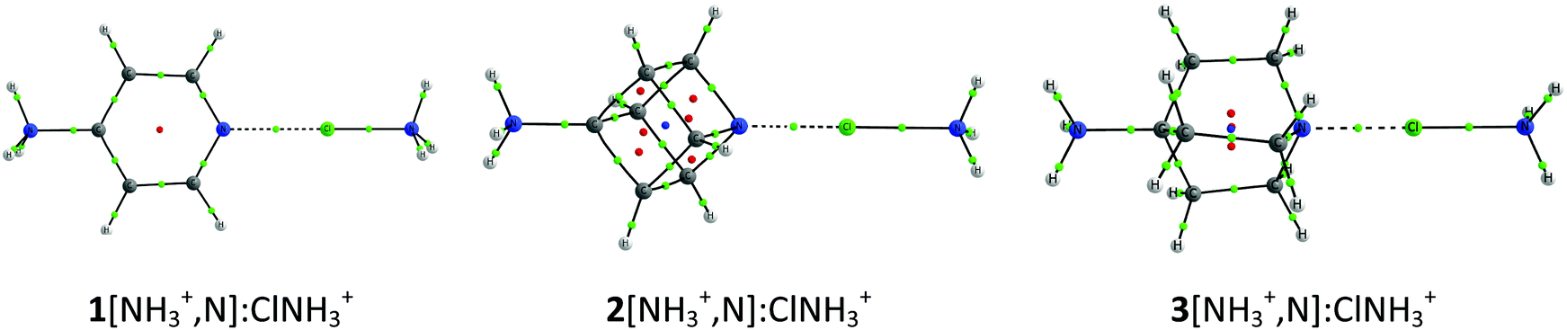 | ||
| Fig. 2 Molecular graphs of 1–3[NH3+,N]:ClNH3+ cation–cation complexes. The molecular graphs of all the complexes are provided in Table S1 of the ESI.† | ||
| E b | |||
|---|---|---|---|
| XNH3+ | 1[NH3+,N] | 2[NH3+,N] | 3[NH3+,N] |
| ClNH3+ | 117.6 | 83.6 | 82.2 |
| BrNH3+ | 92.9 | 54.5 | 57.9 |
| INH3+ | 76.7 | 38.5 | 48.1 |
| 1[NH3+,N] | 2[NH3+,N] | 3[NH3+,N] | ||||
|---|---|---|---|---|---|---|
| XNH3+ | N(B)⋯X | X⋯NH3+ | N(B)⋯X | X⋯NH3+ | N(B)⋯X | X⋯NH3+ |
| ClNH3+ | 2.267 | 1.834 | 1.980 | 2.019 | 2.008 | 2.022 |
| BrNH3+ | 2.232 | 2.038 | 2.107 | 2.132 | 2.147 | 2.124 |
| INH3+ | 2.375 | 2.242 | 2.289 | 2.296 | 2.332 | 2.288 |
The geometry of the cation–cation complexes in gas phase (Table 1) shows that the halogen atoms are located approximately half way between the ammonium group and the nitrogen of the electron donor systems which indicates that the systems correspond to halogen shared complexes.63–65 In complexes with 1, the 1[NH3+,N]N⋯X interaction distance is between 0.43 and 0.13 Å longer than the X–NH3 distance, decreasing as the size of X increases. In complexes of 2 and 3, the 2/3[NH3+,N]N⋯X distance is even slightly shorter than the X–NH3 distance (between 0.04 and 0.01 Å) for all the complexes of 2 and the chlorine complex of 3. The 3[NH3+,N]N⋯X distances for X = Br and I are slightly longer than the X–NH3 distances (0.02 and 0.04 Å, respectively).
To corroborate the present results, we have considered the reorganization of the halogen-bonded systems to give rise to hydrogen-bonded complexes by computing the cation–cation hydrogen-bonded systems as well. Of the 9 complexes, only in two cases the hydrogen bond is competitive with the halogen bond, whereas for the remaining 7 complexes halogen-bonded complexes are more stable than the hydrogen-bonded ones (Table S2, ESI†).
In the case of the anion–anion complexes, four carboxylate systems as halogen bond donors (1–3[CO2−,C–X] and 4[CO2−,N–X] with X = Br and I) have been confronted to the halide anions (F−, Cl−, Br− and I−). Of the 32 possible complexes, only 18 are stable in gas phase (Fig. 3 and Table S1, ESI†), while the rest dissociate spontaneously. The binding energies of these complexes range between 58 and 140 kJ mol−1. Similarly to the cation–cation complexes, among the anion–anion complexes the iodine derivative complexes are between 24 and 57 kJ mol−1 more stable than the corresponding bromine complexes when the latter minima are located, and the smallest binding energy is observed for 4[CO2−,C–I]:F−, i.e., the complex that includes the XB donor with the deepest σ-hole and the most polarizable anion. With respect to the electron donor molecules, the smaller and more polarizable halide anions, which present a more concentrated charge, are the ones with the smaller binding energies. Therefore, the binding energies follow the order F− < Cl− < Br− < I−.
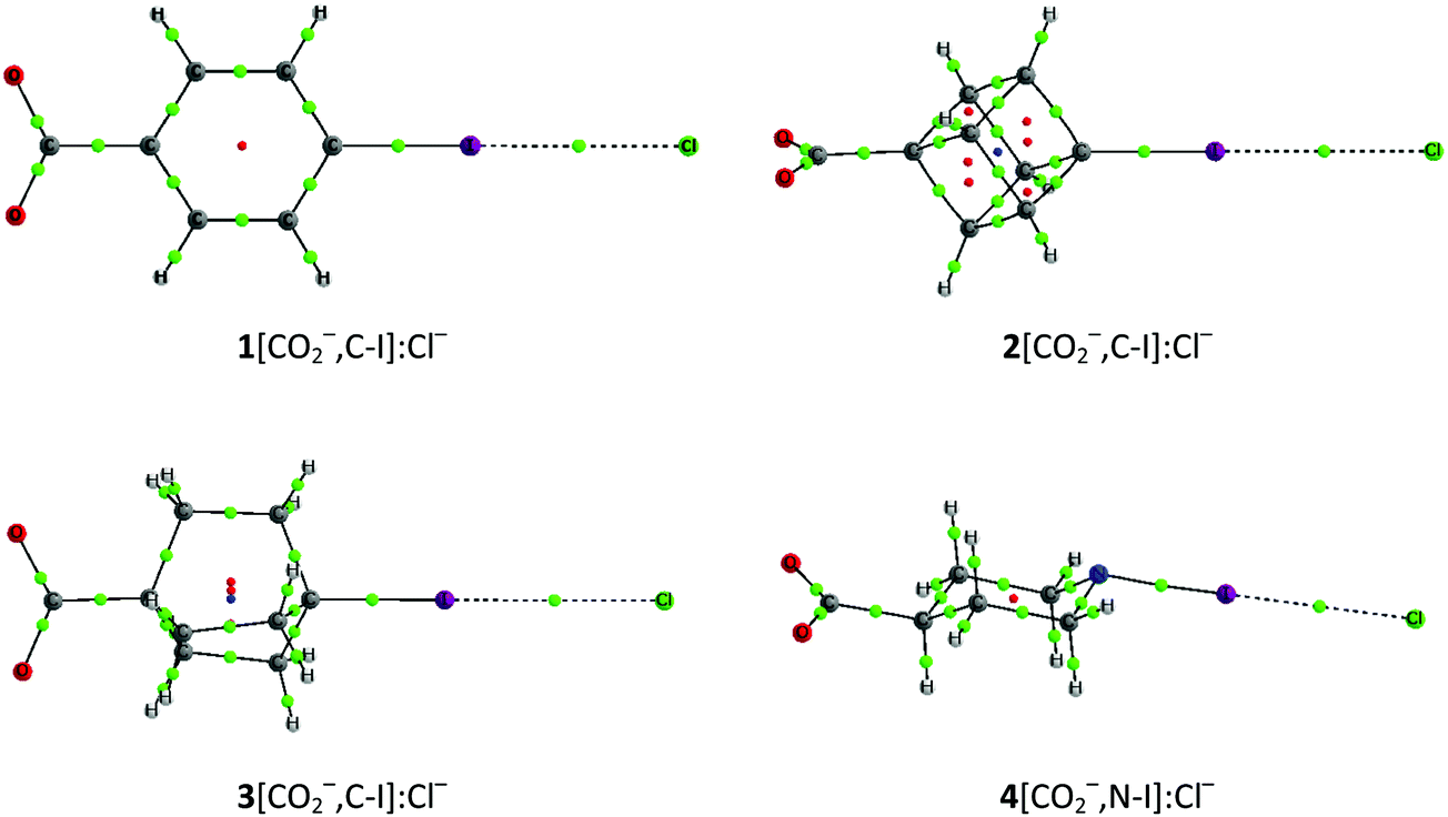 | ||
| Fig. 3 Molecular graphs of 1–3[CO2−,C–I]:Cl− and 4[CO2−,N–I]:Cl− anion–anion complexes. | ||
The distance between the halide anion and the halogen acting as an XB donor ranges between 2.28 and 3.85 Å. The distances increase as the size of the halide increases in its interaction with the same XB donor. In all cases, the distances with F− are much shorter than with the rest of the anions (in average 0.96 Å shorter than the ones with Cl−). In addition, it is observed that the intermolecular distances are smaller in the iodine derivatives than in the bromine analogues by 0.2 Å in average. The effect of the electronegativity of the atom attached to the halogen in the XB donor, that directly affects the σ-hole, is characterized by shorter intermolecular distances in the complexes of 4, where the interacting moiety is N–X, instead of C–X.
It is known that the use of large basis sets with DFT methods minimizes the BSSE effect. Thus, we did not consider calculating it for all systems necessary. However, in order to prove the small effect of the BSSE in our systems, we have calculated it for the minima and TS of complexes 1[NH3+,N]:XNH3+, 1[CO2−,CI]:Y− and the corrected dissociation profiles for 1[NH3+,N]:ClNH3+ and 1[CO2−,CI]:F−. From the results shown in Table S3 (ESI†) we notice that the calculated BSSE is very small for the minima (less than 1.4 kJ mol−1) and even smaller for the TS structures (less than 0.2 kJ mol−1) as expected due to the longer distance between the two interacting systems. In the dissociation profiles (Fig. S1, ESI†), only very small differences in the minima are observed whereas in the rest of the profile both corrected and uncorrected graphic lines are superimposed.
Dissociation scans
The presence of minima with positive binding energy values in gas phase is only possible if a local minimum is present in the potential energy surface with the corresponding dissociation barrier that prevents them to spontaneously dissociate. The dissociation scans (Fig. 4 and Fig. S2 of the ESI†) confirm this point. Starting from the highest point of the scans, the dissociation TS has been located and calculated as the difference in energy between the minima and the TS energies (Table 3).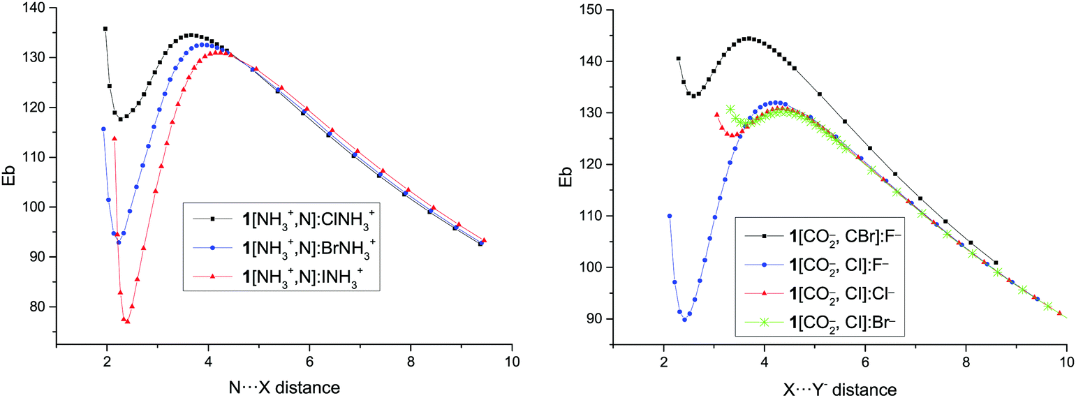 | ||
| Fig. 4 Binding energy (Eb, kJ mol−1) vs. N⋯X intermolecular distance (Å) for the dissociation path of 1[NH3+,N]:XNH3+ complexes and vs. X⋯Y− distance in the 1[CO2−,C–X]:Y− complexes. | ||
| 1[CO2−,C–X] | 2[CO2−,C–X] | 3[CO2−,C–X] | 4[CO2−,N–X] | |||||
|---|---|---|---|---|---|---|---|---|
| X = Br | I | Br | I | Br | I | Br | I | |
| E b | ||||||||
| Y = F− | 133.2 | 89.8 | 147.4 | 109.9 | 155.9 | 118.2 | 115.9 | 58.5 |
| Cl− | — | 125.6 | — | 137.8 | — | 143.3 | 140.0 | 111.9 |
| Br− | — | 127.9 | — | 138.6 | — | — | 140.4 | 116.8 |
| I− | — | — | — | — | — | — | — | 120.2 |
| Distance | ||||||||
| Y = F− | 2.597 | 2.419 | 2.682 | 2.479 | 2.723 | 2.489 | 2.333 | 2.278 |
| Cl− | — | 3.359 | — | 3.499 | — | 3.569 | 3.285 | 3.108 |
| Br− | — | 3.626 | — | 3.854 | — | — | 3.669 | 3.356 |
| I− | — | — | — | — | — | — | — | 3.662 |
| Dissociation barrier | N⋯X distance | |||||
|---|---|---|---|---|---|---|
| 1[NH3+,N] | 2[NH3+,N] | 3[NH3+,N] | 1[NH3+,N] | 2[NH3+,N] | 3[NH3+,N] | |
| ClNH3+ | 16.9 | 51.9 | 57.7 | 3.665 | 4.117 | 3.976 |
| BrNH3+ | 39.7 | 76.6 | 80.4 | 3.887 | 4.355 | 4.147 |
| INH3+ | 54.2 | 88.8 | 88.1 | 4.195 | 4.475 | 4.338 |
| 1[CO2−,C–X] | 2[CO2−,C–X] | 3[CO2−,C–X] | 4[CO2−,N–X] | |||||
|---|---|---|---|---|---|---|---|---|
| X = Br | I | Br | I | Br | I | Br | I | |
| Dissociation barrier | ||||||||
| F− | 11.2 | 42.1 | 6.2 | 30.9 | 3.5 | 27.3 | 27.1 | 70.1 |
| Cl− | — | 5.3 | — | 1.5 | — | 0.5 | 1.3 | 15.4 |
| Br− | — | 2.3 | — | 0.0 | — | — | 0.2 | 9.7 |
| I− | — | — | — | — | — | — | — | 5.4 |
| X⋯Y− distance | ||||||||
| F− | 3.692 | 4.230 | 3.534 | 4.037 | 3.479 | 3.974 | 3.772 | 4.356 |
| Cl− | — | 4.305 | — | 4.149 | — | 4.054 | 3.851 | 4.517 |
| Br− | — | 4.375 | — | 4.149 | — | — | 3.886 | 4.578 |
| I− | — | — | — | — | — | — | — | 4.697 |
The smallest dissociation barriers are obtained for the least stable minima, while the largest are found in the most stable ones. Thus, the dissociation barrier of the least stable cation–cation complex, 1[NH3+,N]:ClNH3+, is only 17 kJ mol−1, while those of the most stable complexes, 2/3[NH3+,N]:INH3+, are 89 and 88 kJ mol−1, in each series. In the case of the anion–anion complexes, only the F− complexes present significant barriers (up to 70 kJ mol−1), while in the rest of the complexes the largest reaches only 15 kJ mol−1. In all cases, the largest barriers are found in the systems where iodine atom acts as an XB donor followed by the bromine analogues, with the chlorine derivatives being the ones with the smallest barriers.
The N⋯X distance in the TSs of the cation–cation complexes and the X⋯Y− distance in the TSs of the anion–anion complexes show a similar trend as the dissociation barrier: the longer the distance, the larger the barrier in each series (for the cation–cation complexes) and for every pair of halogens (for the anion–anion complexes).
Corrected binding energies
In order to evaluate the repulsion due to the charges in these systems, the Eb value for the longest distances, where no other interaction saves the Coulombic repulsion is expected, has been used to estimate the effective distance between two point charges that generate a similar repulsion. However, it has to be borne in mind that using a classical point–point Coulombic formula is not correct for overlapping electron densities. The obtained distance in the cation–cation complexes is approximately the one between the middle of the N–X bond in the XNH3+ molecule and the nitrogen of the NH3+ group in the XB acceptor. In the anion–anion complexes, the effective distance is approximately the separation between the halide anion and the C–CO2− middle bond.The calculated corrected binding energy for each point of the dissociation path, Ecorr, obtained by subtracting the repulsion of two points charges located in the mentioned positions has been represented in Fig. 5 and Fig. S3 (ESI†). The results are similar to the curve for the dissociation of neutral systems where the energy increases steadily from the minima towards values close to zero at long distances and the one found in charged hydrogen bonded systems using the same approach.8
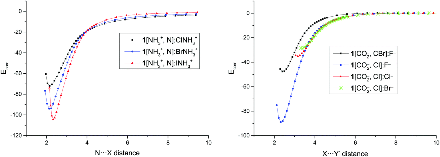 | ||
| Fig. 5 Corrected binding energy (Ecorr, kJ mol−1) vs. N⋯X and X⋯Y− distance (Å) in the dissociation path of 1[NH3+,N]:XNH3+ and 1[CO2−,C–X]:Y− complexes, respectively. | ||
The values of Ecorr obtained in the minima (Table 4) are very large, ranging between −72 and −144 kJ mol−1 for the cationic complexes and between −32 and −117 kJ mol−1 for the anionic derivatives, as those found in very strong halogen bonds as expected for the geometrical characteristics of the minima previously discussed. The values of the Ecorr follow the same trends observed for the Eb: larger values, in absolute value, as the halogen atom increases in each series and as the halide anion decreases. Moreover, cation–cation complexes of 2 and 3 are more stable than those of 1 for the same halogen derivative.
| E corr | |||
|---|---|---|---|
| XNH3+ | 1[NH3+,N] | 2[NH3+,N] | 3[NH3+,N] |
| ClNH3+ | −72.1 | −111.6 | −115.3 |
| BrNH3+ | −94.0 | −135.6 | −133.9 |
| INH3+ | −104.3 | −143.8 | −136.0 |
| E corr | 1[CO2−,C–X] | 2[CO2−,C–X] | 3[CO2−,C–X] | 4[CO2−,N–X] | ||||
|---|---|---|---|---|---|---|---|---|
| X = Br | I | Br | I | Br | I | Br | I | |
| Y = F− | −46.3 | −86.5 | −38.4 | −75.7 | −32.3 | −70.5 | −68.1 | −117.0 |
| Cl− | — | −34.3 | — | −27.1 | — | −24.2 | −25.3 | −49.2 |
| Br− | — | −27.6 | — | −21.4 | — | — | −20.3 | −40.0 |
| I− | — | — | — | — | — | — | — | −31.6 |
Solvent effects
The solvent effects on these XB interactions have been studied using the PCM model with the water parameters. The energetic and geometric results have been gathered in Table 5. Now, the binding energies show negative values as an indication that the complexes are more stable than the isolated monomers, save for two of the anion–anion complexes with small positive values. These results are similar to those reported for hydrogen and halogen bonded complexes between complexes with the same charge in the presence of solvent.2,6,51,66| E H2O | [NH3+,N]N⋯X distance | |||||
|---|---|---|---|---|---|---|
| 1[NH3+,N] | 2[NH3+,N] | 3[NH3+,N] | 1[NH3+,N] | 2[NH3+,N] | 3[NH3+,N] | |
| ClNH3+ | −28.9 | −72.2 | −70.7 | 2.228 | 1.739 | 1.876 |
| BrNH3+ | −60.3 | −97.8 | −98.0 | 2.151 | 2.007 | 2.093 |
| INH3+ | −84.1 | −120.1 | −114.5 | 2.302 | 2.228 | 2.287 |
| 1[CO2−,C–X] | 2[CO2−,C–X] | 3[CO2−,C–X] | 4[CO2−,N–X] | |||||
|---|---|---|---|---|---|---|---|---|
| X = Br | I | Br | I | Br | I | Br | I | |
| E H2O | ||||||||
| Y = F− | −2.5 | −16.2 | 2.0 | −5.8 | 0.9 | −2.4 | −10.0 | −34.0 |
| Cl− | — | −7.9 | — | −3.3 | — | −2.2 | −6.5 | 16.2 |
| Br− | — | −8.1 | — | −3.3 | — | — | −7.2 | −15.9 |
| I− | — | — | — | — | — | — | — | −15.4 |
| Distance | ||||||||
| Y = F− | 2.865 | 2.626 | 3.099 | 2.792 | 4.137 | 2.881 | 2.639 | 2.414 |
| Cl− | — | 3.425 | — | 3.576 | — | 3.667 | 3.305 | 3.211 |
| Br− | — | 3.580 | — | 3.722 | — | — | 3.455 | 3.392 |
| I− | — | — | — | — | — | — | — | 3.617 |
The binding energy values for the cation–cation complexes span between −29 and −120 kJ mol−1. The analysis of the binding energies in gas phase and water indicates that they show the same trend, in fact a good linear correlation can be obtained between them (R2 = 0.985, Fig. S4, ESI†) as an indication that the solvation effect is proportional to the gas phase binding. In the case of the anion–anion complexes, the binding energy range is between +2 and −34 kJ mol−1. In this case, no correlation is found between gas phase complexes and those in water.
The N⋯X distances obtained for the cation–cation complexes in water (Table 5) are in all cases shorter, between 0.04 and 0.24 Å, than the corresponding ones in gas phase. Thus, the complexes have a more ionic character in water than in gas phase. In contrast, the trend observed for the anion–anion X⋯Y− distance is the opposite, with larger distances in water than in gas phase, with only four exceptions, namely 1[CO2−,C–I]:Br−, 2[CO2−,C–I]:Br−, 4[CO2−,N–Br]:Br−, and 4[CO2−,N–I]:I−. The most important lengthenings are observed in the fluoride complexes. A special mention has to be made for 3[CO2−,C–Br]:F− with a remarkable elongation of the Br⋯F− distance of 1.414 Å going from the gas phase to a water solution. The fact that 3[CO2−,C–Br] has the smallest σ-hole among all the XB donor anions coupled with the solvation of the fluoride anion, shielding its polarizing effect, gives rise to a particularly shallow potential energy surface where the energy minimum for this complex has been displaced from 2.723 Å to a 4.137 Å contact distance (Fig. S5, ESI†).
Apart from the PCM continuum solvation model, explicit water molecules were also considered to explore the solvent effects on selected complexes, namely, 1[NH3+,N]:XNH3+ and 4[CO2−,NI]:Y−. In these complexes, three water molecules were included, one interacting with the ionic groups of 1[NH3+,N] and 4[CO2−,NI] and two water molecules interacting with XNH3+ and Y−. Depending on how the water molecules are arranged we will have two configurations A and B (Fig. S6, ESI†), one where the halogen bond observed in the gas phase is retained and another one where no halogen bond is observed, respectively. The results shown in Table S4 (ESI†) indicate that the halogen bond interaction is more stable than the one were a water molecule is located between the two charged molecules in the cation–cation complexes. For the anion–anion complexes, the halogen bond is more stable for the fluoride and chloride anions. Furthermore, implicit solvent effects (PCM) were also considered for the explicitly hydrated 1[NH3+,N]:ClNH3+ and 4[CO2−,NI]:F− complexes, showing that the halogen bonded complexes are lower in energy by 13.2 and 8.7 kJ mol−1, respectively.
Electronic properties (NBO and AIM)
The topological analysis of the electron density within the AIM methodology shows the presence of a single intermolecular BCP between the two interacting moieties (Table S1 of the ESI†). The values of the electron density range between 0.117 and 0.070 a.u. for the cation–cation complexes and between 0.061 and 0.007 a.u. for the anion–anion derivatives (Table S5, ESI†). In addition, positive values of the Laplacian for all the complexes were obtained (between 0.126 and 0.073 a.u., and between 0.187 and 0.018 a.u. for cationic and anionic complexes, respectively), indicating close shell regime interactions. The total electron density, H, is negative for all the cation–cation complexes and the fluoride anion–anion complexes which indicate a partial covalent nature of these interactions.67,68The intermolecular BCPs found in the TS structures show small values of the electron density (between 0.003 and 0.001 a.u.) and positive values of the Laplacian and H, as expected. The properties of these BCPs can classify them as van der Waals contacts. Using the values of all the N⋯X contacts encountered in the cation–cation complexes (gas phase and PCM), an excellent exponential relationship between ρBCP and the interatomic distance for each X atom is observed (R2 > 0.999), in agreement with previous reports on a variety of interactions.69–73 For the X⋯Y− contacts in anion–anion complexes, exponential relationships were also obtained between ρBCP and the contact distance for each halide, with good correlations (R2 > 0.905 in the gas phase and R2 > 0.823 in PCM, Fig. S7 and S8, ESI†). These results are sensibly better (R2 > 0.95) when ∇2ρBCP, instead of ρBCP, is taken into account.
We have examined all possible intermolecular interactions between occupied (donor) Lewis-type NBOs and vacant (acceptor) non-Lewis NBOs and estimated their energetic importance by second-order perturbation theory. According to the NBO analysis, the interaction in the complexes is primarily based on a charge donation from the lone pairs of the nitrogen atom of 1–3 (1–4 for the anion–anion complexes) to the vacant σ* orbital X–N of the X–NH3+ molecule in the cation–cation complexes and from the halide Y− to the vacant σ* orbital of the C–X or N–X bond (σ-hole interaction) in the anion–anion complexes, as derived from the calculated second-order orbital perturbation energies, E(2), listed in Table 6.
| E(2) | Q(XNH3+/Y−) | E(2) | Q(XNH3+/Y−) | ||
|---|---|---|---|---|---|
| a The NBO method is not able to properly divide the complex in its molecular constituents. | |||||
| 1[NH3+,N]:ClNH3+ | 177.7 | 0.8180 | 2[CO2−,C–I]:F− | 85.7 | −0.9093 |
| 1[NH3+,N]:BrNH3+ | 2[CO2−,C–I]:Cl− | 18.5 | −0.9675 | ||
| 1[NH3+,N]:INH3+ | 2[CO2−,C–I]:Br− | 11.4 | −0.9777 | ||
| 2[NH3+,N]:ClNH3+ | 493.6 | 0.6111 | 3[CO2−,C–Br]:F− | 28.9 | −0.9619 |
| 2[NH3+,N]:BrNH3+ | 503.1 | 0.6771 | 3[CO2−,C–I]:F− | 85.6 | −0.9076 |
| 2[NH3+,N]:INH3+ | 320.3 | 0.7521 | 3[CO2−,C–I]:Cl− | 15.9 | −0.9709 |
| 3[NH3+,N]:ClNH3+ | 561.2 | 0.5987 | 4[CO2−,C–Br]:F− | 118.9 | −0.8802 |
| 3[NH3+,N]:BrNH3+ | 450.4 | 0.6777 | 4[CO2−,C–Br]:Cl− | 26.6 | −0.9582 |
| 3[NH3+,N]:INH3+ | 297.8 | 0.7577 | 4[CO2−,C–Br]:Br− | 14.3 | −0.9741 |
| 1[CO2−,C–Br]:F− | 41.4 | −0.9497 | 4[CO2−,C–I]:F− | 197.9 | −0.8432 |
| 1[CO2−,C–I]:F− | 110.6 | −0.8957 | 4[CO2−,C–I]:Cl− | 71.3 | −0.9032 |
| 1[CO2−,C–I]:Cl− | 25.4 | −0.9553 | 4[CO2−,C–I]:Br− | 53.3 | −0.9187 |
| 1[CO2−,C–I]:Br− | 18.4 | −0.9639 | 4[CO2−,C–I]:I− | 39.0 | −0.9307 |
| 2[CO2−,C–Br]:F− | 32.3 | −0.9603 | |||
In the case of the cation–cation complexes, very large E(2) values are obtained (between 178 and 503 kJ mol−1) due to the proximity of the interacting groups (Table 1). In fact, in two of the cases the NBO method is not able to properly recognize the constituent molecules, 1[NH3+,N]:XNH3+ with X = Br and I. A significant charge is transferred from the XNH3+ unit to the electron donor molecule, up to 0.4 e in the 3[NH3+,N]:ClNH3+ complex. These results have to be taken very carefully due to the strong overlap for these systems that are close to form covalent bonds.
In the anion–anion complexes, these charge-transfer contributions are large too, with increasing energies as we move from 1–4[CO2−,C/N–Br] to 1–4[CO2−,C/N–I] for the complexes with fluoride. Thus, E(2) is maximum for complex 4[CO2−,N–I]:F− (197.9 kJ mol−1), the one with the deepest σ-hole, and minimum for 3[CO2−,C–Br]:F− (28.9 kJ mol−1), the one with the shallowest σ-hole. The same trend is also observed for the rest of the halide anions, although with smaller energy contributions than those with the fluoride anion. Moreover, there is an acceptable linear correlation (R2 = 0.80) between the binding energies (Eb, Table 2) and the second-order orbital perturbation energies (E(2) in Table 6) mentioned above for anion complexes. Furthermore, this correlation is greatly improved (R2 = 0.925) when the corrected binding energy, Ecorr, is taken into account instead of Eb, indicating that these Lp(Y−) → σ*(C/N–X) donor–acceptor contributions are very relevant (Fig. 6).
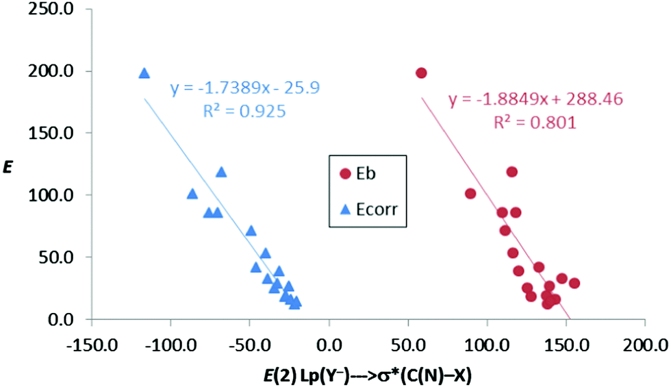 | ||
| Fig. 6 Binding energy (Eb) and corrected binding energy (Ecorr) vs. E(2) (kJ mol−1) for all anion–anion complexes in gas phase. | ||
In addition, we have also compared the charge transfer (absolute values) with the second-order orbital perturbation energies, obtaining a very good linear correlation (R2 = 0.982, Fig. 7) for all ion–ion complexes. Therefore, the larger the E(2) energy, the larger the charge transfer, irrespective of the nature of the ionic complexes.
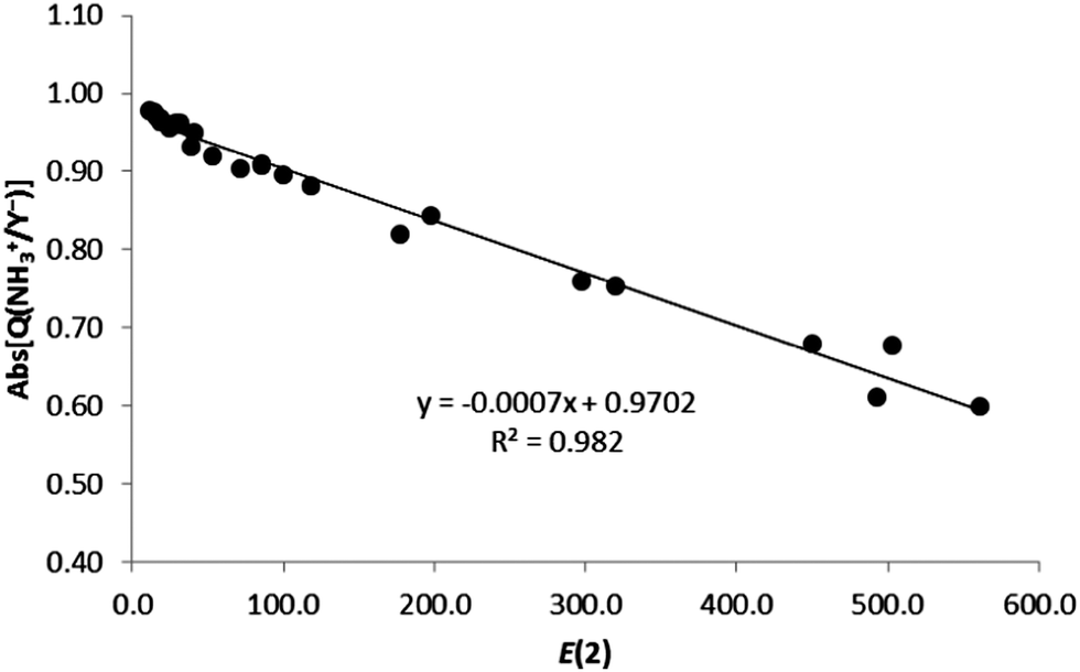 | ||
| Fig. 7 Absolute value of the charge of the ion (Abs[Q(XNH3+/Y−)], in e) vs. E(2) (kJ mol−1) for all complexes in gas phase. | ||
Interestingly, from the comparison of the AIM and NBO results of the anion–anion complexes, excellent exponential correlations have been found between the second-order orbital perturbation energies associated with the C/N–X⋯Y− σ-hole contribution and both the electron density and Laplacian of the electron density at the X⋯Y− bond critical point for every anion series, as depicted in Fig. 8. Most likely, these correlations are due to the fact that ρBCP, ∇2ρBCP (as already noted) and E(2) (R2 > 0.914) present very good exponential correlations with the X⋯Y− distances.
 | ||
| Fig. 8 E(2) (kJ mol−1) vs. electron density (ρ in a.u., up) and Laplacian of the electron density (∇2ρ in a.u., down) at the X⋯Y− BCP for anion–anion complexes in gas phase. | ||
Energy decomposition analysis
The SAPT analysis of the minima (Table S6, ESI†) reveals that the electrostatic term shows positive and negative values, in contrast to a previous report on charge–charge hydrogen bonded complexes where only repulsive electrostatic contributions were found.8 Negative values are associated with all the cation–cation complexes of 2 and 3 and the anion–anion complex 4[CO2−,C–I]:F−. In these cases, the local attraction of the groups involved in the interaction is able to overcome the overall charge–charge repulsion. In fact, for instance, the ESP associated with the σ-hole in 4[CO2−,C–I] changes from −135.5 (Fig. 1) to 307.7 kJ mol−1 when a −1.0 e point charge is placed at the 2.278 Å I⋯F− distance found in 4[CO2−,C–I]:F− (Table 1). Thus, as soon as the XB donor begins to interact with F−, the electron density of each component is polarized by the electric field of the other, resulting in a positive σ-hole on the iodine surface. In all the minima structures, the induction term is attractive ranging between −18 and −416 kJ mol−1. As expected, the absolute value of the induction term increases as the halogen acting as an XB donor increases (increases its polarizability) and as the size of the halide atom decreases (increases its polarizing character).The electrostatic term in all the TSs is positive and corresponds to a relatively narrow range (between +133 and +181 kJ mol−1), dictated by the similar intermolecular distances found in the TS structures. The rest of the terms are much smaller, with the induction term in all cases being attractive. It is significant that the electrostatic term is always more positive in the TS than in the corresponding minimum. This fact has been previously explained based on a loss of the local electrostatic interaction present in the minima.5,8
Moreover, the different SAPT interaction terms were analyzed in an attempt to find a correlation with the binding energy of the complexes. As a result, a very good linear correlation (R2 = 0.920, Fig. 9) was obtained when representing the electrostatic contribution versus the binding energy for the anion–anion complexes. Excellent results (R2 = 0.976, Fig. 9) were also obtained for the corresponding TSs. Moreover, when the corrected binding energy was taken into account excellent linear correlations were obtained not only for the electrostatic term (R2 = 0.946, Fig. S7, ESI†), but also for the induction contribution (R2 = 0.953, Fig. S10, ESI†). This indicates that both electrostatics and, most importantly, the induction term are very important for the formation of the complexes, as also reflected by the charge-transfer contributions from the NBO calculations. However, no correlation was observed between the SAPT interaction terms and the binding energy for the cation–cation counterparts, probably due to the close proximity of the interacting molecules where a partly covalent character of the interaction was expected for these halogen shared complexes.
 | ||
| Fig. 9 Electrostatic contribution (Eel, kJ mol−1) vs. binding energy (Eb, kJ mol−1) for anion–anion complexes and the corresponding transition state structures in gas phase. | ||
CSD search
In an attempt to find experimental evidence of the existence of ion–ion halogen bonds we conducted a search in the Cambridge Structural Database (CSD). Since anion–anion halogen bonds have very recently been the subject of a CSD search,51 we focused on the search of cation–cation halogen bond interactions in the solid state between positively fragments with interacting atoms at less than 3.5 Å. In this regard, no hits were found for the CSD search of fragments defined by the 1–3 nitrogen bases complexes. However, a search for halogen–halogen and nitrogen–halogen interactions for positively charged derivatives p-haloanilines yields interesting hits. The results show a large number of fluorine–fluorine interactions, a smaller set of Cl⋯Cl as well as other halogen–halogen interactions where iodine is not involved (Table S7, ESI†). Instead, halogen–nitrogen interactions are very scarce (Table S7, ESI†) obtaining only three interesting results with two of them being very remarkable (Fig. 10); for the ROBZOX structure, a close contact is observed between the chlorine atom of a p-chloroaniline and a nitrogen atom of a triazole. For the structure with reference code EFUXIN, the terminal nitrogen of the diazonium cation interacts with the iodine atom of a second diazonium cation. | ||
| Fig. 10 Partial views of the two X-ray structures of the derivatives of p-haloanilines retrieved from the CSD with reference codes ROBZOX (top) and EFUXIN (bottom). Distances are given in angstroms. | ||
Conclusions
All XB donors exhibit regions of maxima of the electrostatic potential energies, either negative (cations) or positive (anions), in the halogen atom, associated with its σ-hole. Theoretical calculations predict energy minima in halogen bonded complexes between molecules with the same charge (cation–cation or anion–anion). The binding energies of the complexes in gas phase are positive indicating that they are thermodynamically less stable than the isolated monomers. However, these ion–ion complexes are kinetically stable because the characterized dissociation barrier prevents the spontaneous dissociation of the complexes. Once the electrostatic repulsion between the net charges of the molecules is removed, the energetic profile resembles those of the dissociation of neutral systems. In the same way, hydration of our systems, by means of the PCM methodology, reduces the electrostatic repulsion providing negative binding energies for most of the complexes.The analysis of the electronic properties of the complexes in gas phase has been carried out by means of the AIM and NBO methodologies. The topological analysis of the electron density shows the presence of one intermolecular bond critical point and its associated bond path linking the two monomers in each complex. The properties at these critical points reveal a partial covalent nature of these interactions for all cation–cation and fluoride complexes. The NBO calculations show the presence of large charge transfer stabilizing energies, E(2), in both cation–cation and anion–anion complexes similar to those found in neutral systems with close contact of the monomers. Correlations have been found between the binding energies and E(2) as well as between the electron density parameters at the intermolecular bond critical point and E(2).
The SAPT calculation shows that the electrostatic contribution is positive for all complexes except for cationic complexes 2–3 and 4[CO2−,N–I]:F− for which this term is attractive. The induction contribution is also important and, particularly, manifests a linear correlation with the electrostatically corrected energy in anion–anion complexes. This correlation is not observed in cation–cation complexes because of the close proximity of the interacting cations (between 1.83 and 2.37 Å) resulting in halogen shared complexes. Moreover, the electrostatic term in the dissociation TSs is always more repulsive than in the corresponding minima as an indication that some attractive electrostatic term present in the minima vanishes in the TSs. As expected, the induction contribution in the TSs is smaller than in the complexes because the contact distances are longer for the former than for the latter.
A CSD search for derivatives of p-haloanilines supports our theoretical results by revealing the existence of halogen–halogen and halogen–nitrogen interactions.
From all the above considerations, we conclude that these halogen bonded species are expected to be experimentally detected (at least several of them) in the gas phase as a result of the considerably deep energetic wells of the corresponding minima, up to 88.8 and 70.1 kJ mol−1 for the cationic and anionic complexes, respectively.
Acknowledgements
This work was carried out with financial support from the Ministerio de Economía y Competitividad (project CONSOLIDER-Ingenio 2010 CSD2010-0065, Fondo Europeo de Desarrollo Regional (FEDER) funds and project no. CTQ2015-63997-C2-2-P and CTQ2014-57393-C2-1-P) and Comunidad Autónoma de Madrid (S2013/MIT2841, Fotocarbon). David Quiñonero thanks the MINECO of Spain for a “Ramón y Cajal” contract. Thanks are also given to the CTI (CSIC) for their continued computational support.References
- S. R. Kass, J. Am. Chem. Soc., 2005, 127, 13098–13099 CrossRef CAS PubMed.
- I. Mata, I. Alkorta, E. Molins and E. Espinosa, Chem. Phys. Lett., 2013, 555, 106–109 CrossRef CAS.
- I. Mata, I. Alkorta, E. Molins and E. Espinosa, ChemPhysChem, 2012, 13, 1421–1424 CrossRef CAS PubMed.
- F. Weinhold and R. A. Klein, Angew. Chem., 2014, 126, 11396–11399 CrossRef.
- G. Frenking and G. F. Caramori, Angew. Chem., Int. Ed., 2015, 54, 2596–2599 CrossRef CAS PubMed.
- I. Mata, E. Molins, I. Alkorta and E. Espinosa, J. Phys. Chem. A, 2015, 119, 183–194 CrossRef CAS PubMed.
- M. Pszona, K. Haupa, A. Bil, K. Mierzwicki, Z. Szewczuk and Z. Mielke, J. Mass Spectrom., 2015, 50, 127–135 CrossRef CAS PubMed.
- I. Alkorta, I. Mata, E. Molins and E. Espinosa, Chem. – Eur. J., 2016, 22, 9226–9234 CrossRef CAS PubMed.
- P. Metrangolo, G. Resnati, T. Pilati and S. Biella, Struct. Bonding, 2008, 126, 105–136 CrossRef CAS.
- J. S. Murray, P. Lane and P. Politzer, J. Mol. Model., 2009, 15, 723–729 CrossRef CAS PubMed.
- P. Politzer, J. S. Murray and T. Clark, Phys. Chem. Chem. Phys., 2013, 15, 11178–11189 RSC.
- T. Clark, M. Hennemann, J. S. Murray and P. Politzer, J. Mol. Model., 2007, 13, 291–296 CrossRef CAS PubMed.
- G. Desiraju, P. Ho, L. Kloo, A. Legon, R. Marquardt, P. Metrangolo, P. Politzer, G. Resnati and K. Rissanen, Pure Appl. Chem., 2013, 85, 1711–1713 CrossRef CAS.
- J. Rezac, K. E. Riley and P. Hobza, J. Chem. Theory Comput., 2012, 8, 4285–4292 CrossRef CAS PubMed.
- P. Auffinger, F. A. Hays, E. Westhof and P. S. Ho, Proc. Natl. Acad. Sci. U. S. A., 2004, 101, 16789–16794 CrossRef CAS PubMed.
- A. R. Voth, F. A. Hays and P. S. Ho, Proc. Natl. Acad. Sci. U. S. A., 2007, 104, 6188–6193 CrossRef CAS PubMed.
- P. Metrangolo, Y. Carcenac, M. Lahtinen, T. Pilati, K. Rissanen, A. Vij and G. Resnati, Science, 2009, 323, 1461–1464 CrossRef CAS PubMed.
- P. Metrangolo, T. Pilati, G. Terraneo, S. Biella and G. Resnati, CrystEngComm, 2009, 11, 1187–1196 RSC.
- C. B. Aakeroy, T. K. Wijethunga, J. Benton and J. Desper, Chem. Commun., 2015, 51, 2425–2428 RSC.
- X. Q. Yan, Q. J. Shen, X. R. Zhao, H. Y. Gao, X. Pang and W. J. Jin, Anal. Chim. Acta, 2012, 753, 48–56 CrossRef CAS PubMed.
- Y. Lu, T. Shi, Y. Wang, H. Yang, X. Yan, X. Luo, H. Jiang and W. Zhu, J. Med. Chem., 2009, 52, 2854–2862 CrossRef CAS PubMed.
- S. Sirimulla, J. B. Bailey, R. Vegesna and M. Narayan, J. Chem. Inf. Model., 2013, 53, 2781–2791 CrossRef CAS PubMed.
- Y. Lu, Y. Wang and W. Zhu, Phys. Chem. Chem. Phys., 2010, 12, 4543–4551 RSC.
- A. Bruckmann, M. Pena and C. Bolm, Synlett, 2008, 900–902 CAS.
- S. P. Bew, P. A. Ashford, S. A. Fairhurst, D. L. Hughes, L. Legentil, J. Liddle, P. Pesce, S. Nigudkar and M. A. Wilson, Org. Lett., 2009, 11, 4552–4555 CrossRef CAS PubMed.
- S. M. Walter, F. Kniep, E. Herdtweck and S. M. Huber, Angew. Chem., 2011, 50, 7187–7191 CrossRef CAS PubMed.
- F. Kniep, S. M. Walter, E. Herdtweck and S. M. Huber, Chemistry, 2012, 18, 1306–1310 CrossRef CAS PubMed.
- F. Kniep, S. H. Jungbauer, Q. Zhang, S. M. Walter, S. Schindler, I. Schnapperelle, E. Herdtweck and S. M. Huber, Angew. Chem., 2013, 52, 7028–7032 CrossRef CAS PubMed.
- A. Mele, P. Metrangolo, H. Neukirch, T. Pilati and G. Resnati, J. Am. Chem. Soc., 2005, 127, 14972–14973 CrossRef CAS PubMed.
- G. Gattuso, A. Pappalardo, M. Parisi, I. Pisagatti, F. Crea, R. Liantonio, P. Metrangolo, W. Navarrini, G. Resnati, T. Pilati and S. Pappalardo, Tetrahedron, 2007, 63, 4951–4958 CrossRef CAS.
- C. J. Serpell, N. L. Kilah, P. J. Costa, V. Felix and P. D. Beer, Angew. Chem., 2010, 49, 5322–5326 CrossRef CAS PubMed.
- E. Dimitrijevic, O. Kvak and M. S. Taylor, Chem. Commun., 2010, 46, 9025–9027 RSC.
- N. Busschaert, C. Caltagirone, W. Van Rossom and P. A. Gale, Chem. Rev., 2015, 115, 8038–8155 CrossRef CAS PubMed.
- L. González, F. Zapata, A. Caballero, P. Molina, C. Ramírez de Arellano, I. Alkorta and J. Elguero, Chem. – Eur. J., 2016, 22, 7533–7544 CrossRef PubMed.
- P. Metrangolo, F. Meyer, T. Pilati, G. Resnati and G. Terraneo, Angew. Chem., 2008, 47, 6114–6127 CrossRef CAS PubMed.
- O. Bolton, K. Lee, H. J. Kim, K. Y. Lin and J. Kim, Nat. Chem., 2011, 3, 205–210 CrossRef CAS PubMed.
- G. Cavallo, S. Biella, J. Lu, P. Metrangolo, T. Pilati, G. Resnati and G. Terraneo, J. Fluorine Chem., 2010, 131, 1165–1172 CrossRef CAS.
- R. Bertani, P. Metrangolo, A. Moiana, E. Perez, T. Pilati, G. Resnati, I. Rico-Lattes and A. Sassi, Adv. Mater., 2002, 14, 1197–1201 CrossRef CAS.
- A. Zakrassov, V. Shteiman, Y. Sheynin, M. Botoshansky, M. Kapon, M. Kaftory, R. Del Sesto and J. Miller, Helv. Chim. Acta, 2003, 86, 1234–1245 CrossRef CAS.
- A. Forni, P. Metrangolo, T. Pilati and G. Resnati, Cryst. Growth Des., 2004, 4, 291–295 CAS.
- J. Syssa-Magale, K. Boubekeur, P. Palvadeau, A. Meerschaut and B. Schollhorn, J. Mol. Struct., 2004, 691, 79–84 CrossRef CAS.
- E. Cariati, A. Forni, S. Biella, P. Metrangolo, F. Meyer, G. Resnati, S. Righetto, E. Tordin and R. Ugo, Chem. Commun., 2007, 2590–2592 RSC.
- G. R. Hanson, P. Jensen, J. McMurtrie, L. Rintoul and A. S. Micallef, Chem. – Eur. J., 2009, 15, 4156–4164 CrossRef CAS PubMed.
- G. Berger, J. Soubhye and F. Meyer, Polym. Chem., 2015, 6, 3559–3580 RSC.
- H. L. Nguyen, P. N. Horton, M. B. Hursthouse, A. C. Legon and D. W. Bruce, J. Am. Chem. Soc., 2004, 126, 16–17 CrossRef CAS PubMed.
- J. Xu, X. Liu, T. Lin, J. Huang and C. He, Macromolecules, 2005, 38, 3554–3557 CrossRef CAS.
- J. Xu, X. Liu, J. Ng, T. Lin and C. He, J. Mater. Chem., 2006, 16, 3540–3545 RSC.
- P. Metrangolo, C. Prasang, G. Resnati, R. Liantonio, A. C. Whitwood and D. W. Bruce, Chem. Commun., 2006, 3290–3292 RSC.
- N. Houbenov, R. Milani, M. Poutanen, J. Haataja, V. Dichiarante, J. Sainio, J. Ruokolainen, G. Resnati, P. Metrangolo and O. Ikkala, Nat. Commun., 2014, 5, 4043 Search PubMed.
- L. Meazza, J. A. Foster, K. Fucke, P. Metrangolo, G. Resnati and J. W. Steed, Nat. Chem., 2013, 5, 42–47 CrossRef CAS PubMed.
- G. Wang, Z. Chen, Z. Xu, J. Wang, Y. Yang, T. Cai, J. Shi and W. Zhu, J. Phys. Chem. B, 2016, 120, 610–620 CrossRef CAS PubMed.
- Y. Zhao and D. Truhlar, Theor. Chem. Acc., 2008, 120, 215–241 CrossRef CAS.
- T. H. Dunning, J. Chem. Phys., 1989, 90, 1007–1023 CrossRef CAS.
- S. F. Boys and F. Bernardi, Mol. Phys., 1970, 19, 553–566 CrossRef CAS.
- M. J. Frisch, G. W. Trucks, H. B. Schlegel, G. E. Scuseria, M. A. Robb, J. R. Cheeseman, G. Scalmani, V. Barone, B. Mennucci, G. A. Petersson, H. Nakatsuji, M. Caricato, X. Li, H. P. Hratchian, A. F. Izmaylov, J. Bloino, G. Zheng, J. L. Sonnenberg, M. Hada, M. Ehara, K. Toyota, R. Fukuda, J. Hasegawa, M. Ishida, T. Nakajima, Y. Honda, O. Kitao, H. Nakai, T. Vreven, J. A. Montgomery Jr., J. E. Peralta, F. Ogliaro, M. J. Bearpark, J. Heyd, E. N. Brothers, K. N. Kudin, V. N. Staroverov, R. Kobayashi, J. Normand, K. Raghavachari, A. P. Rendell, J. C. Burant, S. S. Iyengar, J. Tomasi, M. Cossi, N. Rega, N. J. Millam, M. Klene, J. E. Knox, J. B. Cross, V. Bakken, C. Adamo, J. Jaramillo, R. Gomperts, R. E. Stratmann, O. Yazyev, A. J. Austin, R. Cammi, C. Pomelli, J. W. Ochterski, R. L. Martin, K. Morokuma, V. G. Zakrzewski, G. A. Voth, P. Salvador, J. J. Dannenberg, S. Dapprich, A. D. Daniels, Ö. Farkas, J. B. Foresman, J. V. Ortiz, J. Cioslowski and D. J. Fox, Gaussian, Inc., Wallingford, CT, USA, 2009.
- H. J. Werner, P. J. Knowles, G. Knizia, F. R. Manby and M. Schtz, Wiley Interdiscip. Rev.: Comput. Mol. Sci., 2012, 2, 242–253 CrossRef CAS.
- J. Tomasi, B. Mennucci and R. Cammi, Chem. Rev., 2005, 105, 2999–3094 CrossRef CAS PubMed.
- R. F. W. Bader, Atoms in Molecules: A Quantum Theory, Clarendon Press, Oxford, 1990 Search PubMed.
- P. L. A. Popelier, Atoms In Molecules. An introduction, Prentice Hall, Harlow, England, 2000 Search PubMed.
- T. A. Keith, Version 15.09.27 edn., 2015, pp. TK Gristmill Software, (http://aim.tkgristmill.com).
- A. E. Reed, L. A. Curtiss and F. Weinhold, Chem. Rev., 1988, 88, 899–926 CrossRef CAS.
- E. D. Glendening, A. E. Reed, J. E. Carpenter and F. Weinhold, NBO Version 3.1, Theoretical Chemistry Institute, University of Wisconsin, Madison, 1990.
- J. E. Del Bene, I. Alkorta and J. Elguero, J. Phys. Chem. A, 2010, 114, 12958–12962 CrossRef CAS PubMed.
- I. Alkorta, J. Elguero and J. E. Del Bene, J. Phys. Chem. A, 2014, 118, 4222–4231 CrossRef CAS PubMed.
- S. B. Hakkert and M. Erdélyi, J. Phys. Org. Chem., 2015, 28, 226–233 CrossRef CAS.
- A. Shokri, M. Ramezani, A. Fattahi and S. R. Kass, J. Phys. Chem. A, 2013, 117, 9252–9258 CrossRef CAS PubMed.
- D. Cremer and E. Kraka, Croat. Chem. Acta, 1984, 57, 1259–1281 Search PubMed.
- I. Rozas, I. Alkorta and J. Elguero, J. Am. Chem. Soc., 2000, 122, 11154–11161 CrossRef CAS.
- O. Knop, R. J. Boyd and S. C. Choi, J. Am. Chem. Soc., 1988, 110, 7299–7301 CrossRef CAS.
- I. Alkorta, L. Barrios, I. Rozas and J. Elguero, THEOCHEM, 2000, 496, 131–137 CrossRef CAS.
- O. Knop, K. N. Rankin and R. J. Boyd, J. Phys. Chem. A, 2001, 105, 6552–6566 CrossRef CAS.
- E. Espinosa, I. Alkorta, J. Elguero and E. Molins, J. Chem. Phys., 2002, 117, 5529–5542 CrossRef CAS.
- I. Mata, E. Molins, I. Alkorta and E. Espinosa, J. Phys. Chem. A, 2007, 111, 6425–6433 CrossRef CAS PubMed.
Footnote |
| † Electronic supplementary information (ESI) available. See DOI: 10.1039/c6cp03662g |
| This journal is © the Owner Societies 2016 |