 Open Access Article
Magnetomigration of rare-earth ions in inhomogeneous magnetic fields†
Agnieszka
Franczak
a,
Koen
Binnemans
b and
Jan Fransaer
*a
aDepartment of Materials Engineering, KU Leuven, Kasteelpark Arenberg 44, 3001 Heverlee, Belgium. E-mail: Jan.Fransaer@mtm.kuleuven.be
bDepartment of Chemistry, KU Leuven, Celestijnenlaan 200 F, 3001 Heverlee, Belgium
First published on 14th September 2016
Abstract
The effects of external inhomogenous (gradient) magnetic fields on the movement of the rare-earth ions: Dy3+, Gd3+ and Y3+, in initially homogeneous aqueous solutions have been investigated. Differences in the migration of rare-earth ions in gradient magnetic fields were observed, depending on the magnetic character of the ions: paramagnetic ions of Dy3+ and Gd3+ move towards regions of the sample where the magnetic field gradient is the strongest, while diamagnetic ions of Y3+ move in the opposite direction. It has been showed that the low magnetic field gradients, such the ones generated by permanent magnets, are sufficient to observe the magnetomigration effects of the ions in solution. The present work clearly establishes the behavior of magnetically different ions in initially homogeneous aqueous solutions exposed to magnetic field gradients. To this avail, a methodology for measuring the local concentration differences of metal ions in liquid samples was developed.
Introduction
It is well-known that an external inhomogeneous magnetic field can induce transport of ions and molecules in solution.1–6 This magnetomigration of ions and molecules is observed in inhomogeneous (gradient) magnetic fields in which the position of species in solution depends on the magnetic field strength at each point. In the presence of an inhomogeneous magnetic field, the magnetic field on an ion immersed in a solution is the magnetic field gradient force (Kelvin force), which can be written as:7–15 | (1) |
![[B with combining right harpoon above (vector)]](https://www.rsc.org/images/entities/i_char_0042_20d1.gif) is the magnetic field [T], ∇
is the magnetic field [T], ∇![[B with combining right harpoon above (vector)]](https://www.rsc.org/images/entities/i_char_0042_20d1.gif) is the magnetic field gradient [T m−1] and μ0 is the magnetic permeability of vacuum [4π 10−7 H m−1].
is the magnetic field gradient [T m−1] and μ0 is the magnetic permeability of vacuum [4π 10−7 H m−1].
The magnitude of the magnetic forces acting on species in solution is determined by the magnetic character of metal ions and molecules which can be either paramagnetic or diamagnetic. Paramagnetic species are characterized by the presence of unpaired electrons in atomic or molecular orbitals.16 Electrons have spins that can be considered as permanent magnetic dipole moments. In the absence of an external magnetic field the magnetic dipole moments are randomly oriented, cancelling each other on a macroscopic scale. When an external magnetic field is applied, the magnetic dipole moments of the paramagnetic species become aligned with the lines of the magnetic field flux, leading to a net magnetization:14,17
| M = χH | (2) |
The theory of Brownian motion predicts that the smaller the particle size the larger its mean-squared displacement. The energy carried by the magnetic field is much lower than kBT at room temperature (kB being the Boltzmann constant and T the absolute temperature) and hence, any form of magnetic migration is eradicated by the thermal noise.7 Moreover, even if an excited state was induced in an ion by a magnetic field, it should rapidly disappear as a result of the thermal collisions when the magnetic field is removed.19,20 Nevertheless, remarkable effects have recently been observed for aqueous solutions in external magnetic fields.21–24 Schadewal et al.7 investigated the influence of a magnetic gradient force on the distribution of dissolved paramagnetic Fe2+ ions at different concentrations, directions of the magnetic field gradient and magnetic field strength. Experiments on solutions consisting of paramagnetic Fe2+ ions showed a significant increase in the Fe2+ ions concentration when a magnetic field gradient was applied. The effect of gradient magnetic fields on different paramagnetic transition metal ions was also studied by Fujiwara et al.25–28 Paramagnetic ions, such as Fe3+, Co2+, Ni2+ and Cu2+ were spotted on a silica gel support. The ions moved in the direction of the strongest gradient magnetic fields. The authors showed that the extent of displacement of ion-containing silica particles depended on the magnetic susceptibility of the ions, their adsorption properties on the silica particles and their concentration. Yang et al.29–31 demonstrated that paramagnetic Mn2+ and Dy3+ ions in a homogeneous aqueous solution can be locally enriched by means of a superimposed gradient magnetic field and this enrichment depended on the magnetic susceptibility of the considered metal ions. Because the effects of an external magnetic field on species in the liquid samples are rather difficult to observe due to the occurrence of a natural convection when the magnetic field is removed, Yang et al.30,31 and Uhlemann et al.9 used a Mach–Zehnder interferometry to investigate the concentration gradient of paramagnetic metal ions in initially homogeneous solutions caused by the application of a magnetic field generated by NdFeB magnets. This method allows for observation of the concentration changes of metal ions in solution caused by an inhomogeneous magnetic field, but it is an indirect method and it cannot be used for observation of the liquid samples in the bore of a superconducting magnet.
Most of the studies on magnetomigration of metal ions in inhomogeneous magnetic fields were about d-block transition metals. Nevertheless, the magnetic field effects on rare-earth ions are of special interest due to their unique magnetic properties. The rare-earth ions with unpaired electrons are characterized by a large unquenched orbital angular momentum associated with the internal nature of the valence 4f orbitals. With the exception of Gd3+ and Eu2+, which have a 4f7 electronic configuration and an orbitally non-degenerate ground state, and Sc3+, Y3+, La3+ and Lu3+ which have an empty or full 4f shell, all other rare-earth ions possess orbitally degenerated ground states, obtained from the following interactions, given in the decreasing order of their relative strength: the interelectronic repulsion, the spin–orbit coupling and the crystal-field effects.32 Since crystal-field effects are smaller and spin–orbit coupling larger for f electrons in comparison with the d electrons of transition metal ions, the orbital component of the magnetic moment is larger for the rare-earth ions than for the transition metal ions. This is due to the larger nuclear charge of the rare-earth ions. At the same time, the crystal-field of rare-earth ions is much smaller than for d electrons, since the 4f orbitals are compressed and the 4f electrons are screened by the filled outer 5s and 5p shells.33 Hence, paramagnetic rare-earth ions have unique magnetic properties compared to d-block transition metal ions. However, very few studies have been devoted to the magnetomigration of paramagnetic rare-earth ions in magnetic field gradients.30,34,35
In this paper, the effect of external inhomogeneous magnetic fields on the migration of paramagnetic and diamagnetic rare-earth ions is described. For the first time, the magnetomigration of diamagnetic rare-earth ions is reported. These investigations show the development of concentration gradients due to the migration of rare-earth ions in an initially homogeneous solution under applied external inhomogeneous magnetic fields. A novel experimental method is described for the direct measurement of concentration gradients of metal ions caused by an external magnetic field.
Experimental
Materials
Dy(NO3)3·xH2O (Aldrich, 99.9%), Y(NO3)3·6H2O (Alfa Aesar, 99.9%), Gd(NO3)3·6H2O (Sigma-Aldrich, 99.9%).Methods
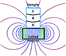
The silicone tubes (2 cm in diameter and 6 cm in length) were used as sample holders. Each holder contained three porous glass disks, saturated with the rare-earth solutions. The disks were pushed closely together and both tube ends were covered by a sheet of Parafilm. The as-prepared samples were placed on top of a permanent magnet (Fig. 1). After exposure to the magnetic field, the rare-earth ions were extracted from the porous glass disks into 100 mL volumetric flasks using a vacuum pump.
Results
The following section discusses two different techniques to study the effect of magnetic field gradients on rare-earth ions: gel samples and porous glass disks. Both experimental approaches prevent natural convection and allow for the chemical analysis of the samples as a function of position after removal of the magnetic field.Two solutions containing paramagnetic ions, one with Dy3+ ions (3 mM) and another with Gd3+ ions (3 mM), and one solution containing diamagnetic Y3+ ions (3 mM) were gelled using gelatin. After achieving a full state of gelling, a stable gel sample containing rare-earth ions was obtained. The as-prepared gel sample in the glass holder was then placed on top of a NdFeB permanent magnet or in the bore of a superconducting magnet for a certain period of time.
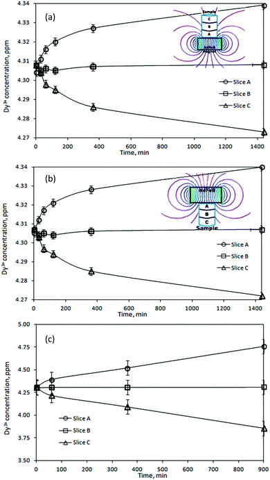
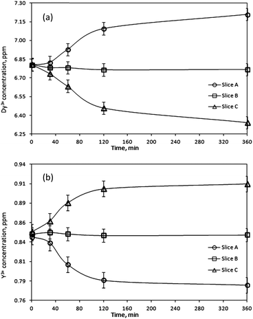
After exposure to the magnetic field, the gel was pushed out of the holder by a micrometer so that the thickness of the extracted pieces could be controlled. In this way, three samples were obtained: slice A – 0–2 mm from the point of the strongest magnetic field gradient, slice B – 2–4 mm, and slice C – 4–6 mm. In accordance with the variation in magnetic field strength as a function of the distance from the magnet surface (see ESI†) each slice of the gel sample was exposed to a magnetic field of a different strength. Therefore, the concentration of the rare-earth ions was expected to vary from slice to slice. To verify this, the slices were re-dissolved and their concentrations were determined by ICP-OES. Fig. 2a shows the results for the gel samples containing Dy3+ ions exposed to the magnetic field generated by a NdFeB permanent magnet. It can be seen that in the initially homogeneous samples of rare-earth ions exposed to a magnetic field gradient, a concentration gradient was induced. The concentration of paramagnetic Dy3+ ions increases in the vicinity of the magnet (0–2 mm, slice A). Thus, the concentration of the paramagnetic Dy3+ ions was enriched in the part of the sample where the magnetic field gradient was the strongest. In Fig. 2a, the enrichment of Dy3+ ions progresses relatively rapidly up to an exposure time of 180 min to the magnetic field and then slows down. However, the steady state had not been achieved yet and the concentration variations of the Dy3+ ions were still observed after 1440 min. After this time, an enrichment of 0.8% with respect to the initial concentration was achieved in slice A. Fig. 2b indicates similar results when changing the position of the permanent magnet: from the bottom of the glass tube to the top of the tube. In order to verify a dependence of the induced concentration gradient on the applied magnetic field gradient, the gel samples containing paramagnetic Dy3+ ions were exposed to the high magnetic field, B = 5 T (BdB/dz = 189 T2 m−1), generated by a superconducting magnet (Fig. 2c). In this case, the Dy3+ gel samples exposed to the high magnetic field gradient during 900 min resulted in the enrichment of Dy3+ ions in slice A of about 10% with respect to the initial concentration. Similar to the previous investigation concerning the low magnetic field gradient, also at high magnetic field gradient the concentration steady state had not been achieved even 900 min after applying the magnetic field. Comparing both results, from low and high magnetic field gradients (Fig. 3), it can be clearly seen that increasing an external magnetic field by 10 fold the enrichment of Dy3+ ions in slice A also significantly increases: by 7 fold after magnetic field exposure during 60 min and 9 fold after magnetic field exposure during 360 min. Similar observations were noticed when using agarose or agar–agar as gelating agents.
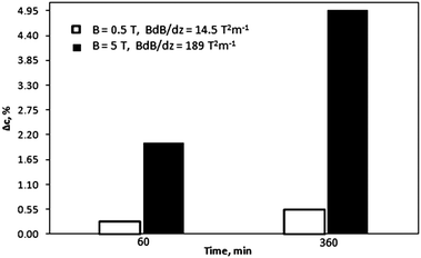 | ||
| Fig. 3 Effect of a magnetic field on the induced concentration gradient in the Dy3+ gel samples (slice A) as a function of time of an applied magnetic field. | ||
To confirm that the observed magneto-induced migration of the paramagnetic Dy3+ ions is caused by an external magnetic field, the magnetic susceptibilities of the gel samples were investigated. The magnetic susceptibility measurements were done for the Dy3+ gel samples exposed to the low magnetic field gradient generated by a NdFeB permanent magnet for various periods of time. Each of the slices extracted after exposure of the gel samples to the magnetic field was closely packed into a glass tube with kept weight control of the sample. The glass tube was then placed between the pole faces of an electromagnet in a way that the tube was exposed to the inhomogeneous magnetic field. The mass changes of the sample after applying the magnetic field were recorded and mass magnetic susceptibility calculated. Fig. 4 shows the average magnetic susceptibilities (after triplicate measurements) of the Dy3+ gel samples as a function of time of the exposure to the magnetic field. It can be seen that the magnetic susceptibility follows the trend of the ion concentration changes (Fig. 2a and b) caused by the presence of an external magnetic field. The magnetomigration of the paramagnetic Dy3+ ions towards the region of the sample where the magnetic field gradient was the strongest (slice A) resulted in a higher concentration of the ions in this region what in consequence reflects in the increased magnetic susceptibility. Thus, the observed concentration gradient formed in the Dy3+ gel samples is definitely caused by the applied external magnetic field.
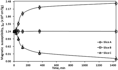 | ||
| Fig. 4 Magnetic susceptibility, χm, of the Dy3+ gel samples after exposure to the magnetic field generated by a NdFeB permanent magnet (B = 0.5 T, BdB/dz = 14.5 T2 m−1). | ||
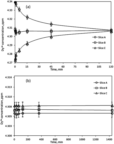
Further confirmation of the magnetic field effects on the migration of ions in solution were investigated by studying the reverse concentration changes when the magnetic field was removed. The Dy3+ gel samples were first exposed to an external magnetic field for 1440 min, after which the magnetic field was removed for various periods of time. The gel samples were extracted in the same way as during magnetic measurements, dividing the gel sample for three identical slices. Fig. 5a shows the Dy3+ concentration changes in the gel after removal of the magnetic field as a function of time. Due to the diffusion of ions in the gel sample, the concentration gradient of Dy3+ ions induced earlier by a magnetic field is lost as ions start to migrate from regions of high concentration to regions of low concentration. As a consequence, 120 min after removal of the magnetic field, the concentration of ions in each gel slice was the same as in the reference sample, before exposing it to the external magnetic field. Additional confirmation of the effect of a magnetic field is the concentration analysis of a reference sample, which was not exposed to an external magnetic field (Fig. 5b). It was observed that the ion distribution in the gel samples was uniform and did not change over time. This indicates that the gel matrix did not influence the experimental results, but just impeded the natural convection in the sample. This also indicates that the magnetic field causes the concentration differences in the gel in the first place.
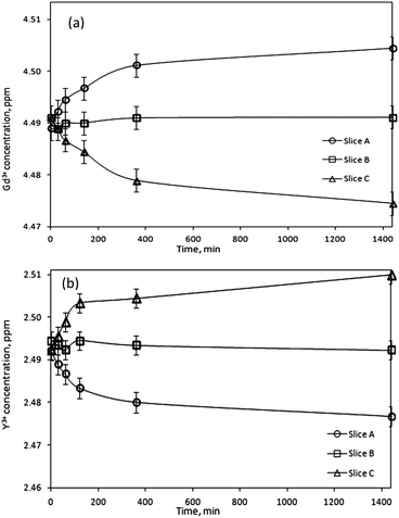
Next, the paramagnetic Gd3+ ions were studied. Fig. 6a shows a concentration increase of 0.6% with respect to the initial concentration, in the region of the sample where the magnetic field gradient was the strongest (slice A), after 1440 min of exposure to the magnetic field. The fact that Gd3+ behaves similarly to the paramagnetic Dy3+ ions under external magnetic field indicates that the observed magnetomigration of paramagnetic rare earths ions is governed by the magnetic moment, unlike the magnetic alignment of rare-earth-containing liquid crystals where the anisotropic and isotropic characters of the rare-earths had to be taken into account.34
However, the behavior of the diamagnetic Y3+ ions was opposite to that of the paramagnetic rare-earth ions and in this case the concentration decreased in the region closest to the magnet surface (0–2 mm, slice A) (Fig. 6b). ICP analysis indicated a decrease of 0.6% in slice A compared to the initial Y3+ concentration. Thus, Y3+ ions are repelled by the magnetic field. Similarly to the Dy3+ and Gd3+ ions, a steady state concentration profile of Y3+ ions was not obtained after 180 min, and the concentration increase of diamagnetic ions at the other side of the sample (4–6 mm, slice C) where the magnetic field strength was the lowest, continues even after 1440 min.
To unequivocally exclude the influence of the gelatin matrix on the observed magnetic field effects on the different rare-earth ions, a second approach based on the use of pure solutions soaked in porous glass disks (without gelatin) was developed. Before each experiment, the porous glass disks were immersed in solutions of Dy3+ (4 mM) or Y3+ (10 mM). The principle of the experimental setup was similar to the one with the gelatin matrix. Thus, samples consisting of three small glass disks, each 2 mm thick, were placed on top of a permanent magnet for a certain period of time. The magnetic exposure time had to be kept much shorter compared to the experiments with the gel samples due to evaporation of the solution. After exposure to the magnetic field, the samples were extracted and the concentration of the rare-earth ions was measured. Fig. 7 shows a similar result to the one observed in the gel samples: the paramagnetic Dy3+ ions moved to the region of the strongest magnetic field localized at the magnet surface (slice A), while the diamagnetic Y3+ ions were repelled and a concentration decrease in the region of the strongest field (slice A) was observed. Experiments on solutions of magnetically different rare-earth ions indicate a 6% increase in concentration of Dy3+ ions and a 7% decrease of Y3+ ions in the strongest magnetic field. However, the concentration changes happen more quickly in porous glass than in gel samples: after 360 min the concentration profile in the glass disks has attained its steady state while in gel samples, the concentration has still not attained its steady state after 1440 min. The faster and larger differences found for the porous glass samples compared to the gel samples are due to the differences in the matrices. In the gelatin matrix, the ions have to move through the interchain voids among the gel fibers, which are of nanometer size. The pore size of the glass disks is much larger, between 40 and 100 μm. Therefore, the motion of ions is less disturbed by interactions with the matrix, increasing their rate of diffusion.
Discussion
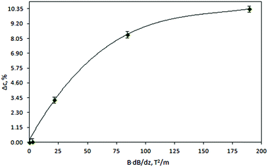
The present work clearly establishes the migration of magnetically different ions in initially homogeneous aqueous solutions exposed to magnetic field gradients. Fig. 8 shows the relative change in the concentration of Dy3+ ions subject to magnetic field gradients of increasing strength compared to the initial Dy3+ concentration. This figure also shows that the concentration difference increases when the magnetic field gradient increases. In steady state, the spatial distribution of the ion concentration, c = c(x), in a one-dimensional system subjected to a magnetic field gradient, ∇B at temperature T, should be proportional to the Boltzmann factor:36 | (3) |
 | (4) |
 , the data of Fig. 8 do not fall on a straight line. Moreover, when a magnetic field of 10 T is applied to a solution of Dy3+ ions for which μeff is 10.63 μB
 at 300 K, the induced concentration change should be equal to:36
 | (5) |
Moreover, considering differences in the magnetic moments of the studied ions, the solution of Y3+ ions, with μeff = 0 μB, under the same experimental conditions should not show any concentration variation, which is at odds with the results shown in Fig. 6b. A similar effect of a magnetic field gradient on diamagnetic ions was also reported by Yang et al.31 when investigating dilute CuSO4 solution: in the vicinity of the strongest magnetic field gradient, a concentration reduction up to Δc ∼ −0.7 mM was observed.
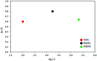
Also, no scaling is observed with the magnetic susceptibility of the ions. This is shown in Fig. 9 where the change in the concentration of Dy3+, Gd3+ and Y3+ ions and their initial concentration is plotted as a function of Δχ = χion − χsol, the difference between the dimensionless ([−]) magnetic susceptibilities of the ions and water (χH2O: −0.16 × 10⁻³ [−]; χDy3+: +1.23 [−], χGd3+: +2.32 [−] and χY3+: +2.3 × 10⁻³ [−]).36–39 This figure shows that the slightly diamagnetic Y3+ ions migrate almost as much under the same circumstances as the strongly paramagnetic Dy3+ and Gd3+ ions. Pulko et al.30 reported similar observation when comparing the concentration gradients of Dy3+ ions to Mn2+ ions, studied earlier by Yang et al.31 In this case, the magnetic field gradient force should be larger for Dy3+ ions because the magnetic susceptibility of Dy3+ exceeds that of Mn2+. Thus, the concentration gradient of Dy3+ ions should be both higher and reached faster than in the case of Mn2+ ions. However, this hypothesis was in contrast with the experimental results: the concentration changes of Dy3+ ions proceed twice as long as for Mn2+ ions, reaching the maximum enrichment twice lower than the one observed for Mn2+ ions in the same experimental setup. Hence, it was suspected that the induced magnetomigration of metal ions is not the migration of single ions, but a group of ions and other species present in solution, surrounding a core ion (cation), such as water molecules.
Fujiwara et al.25–28 investigated the drift motion of metal ions spotted on silica gel and exposed to an inhomogeneous magnetic field. The authors concluded that the motion of ions in an external field is not a motion of single ions but a group of ions and water molecules with an estimated diameter of 2.4 μm. In this case, the magnetic energy acting on the formed group will be much higher than the one acting on a single ion. Gorobets et al.40 showed that ferrous ions formed due to the corrosion of a steel sphere in an external magnetic field follow a defined pattern in solution similar to the one of the magnetic field profile around the sphere. This was explained as a balance between the magnetic pressure and the osmotic pressure nkBT, where n is the number of ions per unit volume, providing that the pressure is reduced by a factor of 104, implying that ions respond collectively to a magnetic field. In this context, Ca2+ ions are now thought to form structured assemblies in water known as “dollops”.24 However, the exact nature of this group formation is not clear yet and requires further investigations. Georgalis et al.41 suggested that it may be attributed to the direct electrostatic interactions between positive cations and negative counter ions, hydrophobic interactions or interaction between ions bearing identical charges caused by exclusion of ions by water molecules what might suggest that the magnetic field effect on ions and molecules in solution is closely related to the behavior of kosmotropic (structure-making) species.
Conclusions
Magnetic field gradients have a measurable effect on strongly paramagnetic Dy3+ and Gd3+, as well as on weakly diamagnetic Y3+ ions in solution. Paramagnetic ions move in the direction of increasing magnetic field, while diamagnetic ions move in the opposite direction. Even magnetic field gradients caused by strong NdFeB magnets are sufficient to induce sizeable concentration gradients in initially homogeneous solution of metal ions. Magnetic field gradients in a superconducting magnet of already 5 T led to concentration changes of the order of 10% in solutions containing Dy3+ ions. It was found that the concentration changes increase when the applied magnetic field gradient increases. The concentration changes however, do not change with the magnetic susceptibility of the ions, and the slightly diamagnetic Y3+ ions migrate almost as much under the same circumstances than the strongly paramagnetic Dy3+ and Gd3+ ions.Acknowledgements
The authors would like to thank Johan Vanacken (Department of Physics and Astronomy, KU Leuven), Joop van Deursen (MTM, KU Leuven) and Avantes for their technical support. The authors thank the KU Leuven (projects IOF-KP RARE3 and GOA GOA/13/008) and the FWO Flanders (project G082716N) for financial support. The research leading to these results has received funding from the European Community's Seventh Framework Programme ([FP7/2007-2013]) under grant agreement no. 607411 (MC-ITN EREAN: European Rare Earth Magnet Recycling Network). This publication reflects only the author's view, exempting the Community from any liability. Project website: http://www.erean.eu.References
- R. Aogaki, T. Negishi, M. Yamato, E. Ito and I. Mogi, Physica B, 1994, 210, 611 CrossRef.
- O. Aaboudi, J.-P. Chopart, J. Douglade, A. Olivier, C. Gabrielli and B. Tribollet, J. Electrochem. Soc., 1990, 137, 1796 CrossRef.
- O. Devos, O. Aaboudi, J.-P. Chopart, E. Merienne, A. Oliver and J. Amblard, J. Electrochem. Soc., 1998, 145, 4139 CrossRef.
- A. Oliver, J.-P. Chopart and J. Douglade, J. Electroanal. Chem., 1987, 217, 443 CrossRef.
- G. Hinds, J. M. D. Coey and M. E. G. Lyons, J. Appl. Phys., 1998, 83, 6449 CrossRef.
- G. Hinds, J. M. D. Coey and M. E. G. Lyons, Electrochem. Commun., 2001, 3, 218 CrossRef.
- U. Schadewald, B. Halbedel, M. Ziolkowski and H. Brauer, International Scientific Colloquium, Modelling for Material Processing, Riga, 2010 Search PubMed.
- T. Weier, K. Eckert, S. Muhlenhoff, C. Cierpka, A. Bund and M. Uhlemann, J. Electrochem. Soc., 2007, 9, 2479 CAS.
- G. Mutschke, K. Tschulik, T. Weier, M. Uhlemann, A. Bund and J. Frohlich, Electrochim. Acta, 2010, 55, 9060 CrossRef CAS.
- A.-L. Daltin, A. Addad, P. Baudart and J.-P. Chopart, CrystEngComm, 2011, 13, 3373 RSC.
- M. Uhlemann, H. Schlorb, H. Msellak and J.-P. Chopart, J. Electrochem. Soc., 2004, 151, C598 CrossRef CAS.
- K. L. Rabah, J.-P. Chopart, H. Schloerb, S. Saulnier, O. Aaboubi, M. Uhlemann, D. Elmi and J. Amblard, J. Electroanal. Chem., 2004, 571, 85 CrossRef CAS.
- M. D. Pullins, K. M. Grant and H. S. White, J. Phys. Chem. B, 2001, 105, 8989 CrossRef CAS.
- M. Uhlemann, K. Tschulik, A. Gebert, G. Mutschke, J. Frohlich, A. Bund, X. Yang and K. Eckert, Eur. Phys. J.: Spec. Top., 2013, 220, 287 CrossRef.
- P. Dunne, R. Soucaille, K. Ackland and J. M. D. Coey, Magnetohydrodyn., 2012, 48, 43 Search PubMed.
- D. J. Griffiths, Introduction to Electrodynamics, Benjamin Cummings, Inc., San Francisco, 3rd edn, 2008, ch. 6 Search PubMed.
- R. S. M. Rikken, R. J. M. Nolte, J. C. Maan, J. C. M. Van Hest, D. A. Wilson and P. C. M. Christianen, Soft Matter, 2014, 10, 1295 RSC.
- R. P. Feynman, R. B. Leighton and M. L. Sands, The Feynman Lectures on Physics, Adison-Wesley, Reading, MA, 1964, vol. 2 Search PubMed.
- J. M. D. Coey, R. Aogaki, F. Byrne and P. Stamenov, Proc. Natl. Acad. Sci. U. S. A., 2009, 106, 8811 CrossRef CAS PubMed.
- P. Dunne and J. M. D. Coey, Phys. Rev. B: Condens. Matter Mater. Phys., 2012, 85, 224411 CrossRef.
- M. C. Amiri and A. A. Dadkhah, Colloids Surf., A, 2006, 278, 252 CrossRef CAS.
- V. Kochmarsky, Magn. Electr. Sep., 1995, 7, 77 CrossRef.
- P. Xiao-Feng and D. Bo, Phys. Rev. B: Condens. Matter Mater. Phys., 2008, 403, 3571 CrossRef.
- R. Demichelis, P. Raiteri, J. D. Gale, D. Quigley and D. Gebauer, Nat. Commun., 2011, 2, 590 CrossRef PubMed.
- M. Fujiwara, D. Kodoi, W. Duan and Y. Tanimoto, J. Phys. Chem. B, 2001, 105, 3343 CrossRef CAS.
- K. Chie, M. Fujiwara, Y. Fujiwara and Y. Tanimoto, J. Phys. Chem. B, 2003, 107, 14374 CrossRef CAS.
- M. Fujiwara, K. Chie, J. Sawai, D. Shimizu and Y. Tanimoto, J. Phys. Chem. B, 2004, 108, 3531 CrossRef CAS.
- M. Fujiwara, K. Mitsuda and Y. Tanimoto, J. Phys. Chem. B, 2006, 110, 13965 CrossRef CAS PubMed.
- X. Yang, K. Tschulik, M. Uhlemann, S. Odenbach and K. Eckert, J. Phys. Chem. Lett., 2012, 3, 3559 CrossRef CAS PubMed.
- B. Pulko, X. Yang, Z. Lei, S. Odenbach and K. Eckert, Appl. Phys. Lett., 2014, 105, 232407 CrossRef.
- X. Yang, K. Tschulik, M. Uhlemann, S. Odenbach and K. Eckert, IEEE Trans. Magn., 2014, 11, 4600804 Search PubMed.
- Y. G. Galyametdinov, W. Haase, B. Goderis, D. Moors, K. Driesen, R. Van Deun and K. Binnemans, J. Phys. Chem. B, 2007, 111, 13881 CrossRef CAS PubMed.
- T. Takeda, T. Kogawa, I. Yamamoto and M. Yamaguchi, Proc. Int. Symp. Magneto-Science, 2006, 2, P34 Search PubMed.
- W. Noddack and E. Wicht, Phys. Chem., 1952, 56, 893 CrossRef CAS.
- I. Noddack and E. Wicht, Chem. Tech., 1955, 7, 3 CAS.
- Landolt-Bornstein, Numerical Data and Functional Relationships in Science and Technology, New Series, II/16, ed. K.-H. Hellwege and A. M. Hellwege, Diamagnetic Susceptibility, Springer-Verlag, Heidelberg, 1986.
- Landolt-Bornstein, Numerical Data and Functional Relationships in Science and Technology, New Series, III/19, Sub-volumes a to i2, W. Martienssen (Ed. in Chief), Magnetic Properties of Metals, Springer-Verlag, Heidelberg, 1986–1992.
- Landolt-Bornstein, Numerical Data and Functional Relationships in Science and Technology, New Series, II/2, II/8, II/10, II/11, and II/12a, Coordination and Organometallic Transition Metal Compounds, Springer-Verlag, Heidelberg, 1966–1984.
- G. Foëx, Tables de constantes et données numériques, Diamagnétisme et paramagnétisme, Relation paramagnétique, Masson, Paris, 1957, vol. 7 Search PubMed.
- O. Y. Gorobets, Y. I. Gorobets, I. A. Bondar and Y. A. Legenkiy, J. Magn. Magn. Mater., 2013, 330, 76 CrossRef CAS.
- Y. Georgalis, A. M. Kierzek and W. Saenger, J. Phys. Chem. B, 2000, 104, 3405 CrossRef CAS.
Footnote |
| † Electronic supplementary information (ESI) available. See DOI: 10.1039/c6cp02575g |
| This journal is © the Owner Societies 2016 |

