 Open Access Article
Creative Commons Attribution 3.0 Unported Licence
Deactivation pathways of thiophene and oligothiophenes: internal conversion versus intersystem crossing†
Patrick
Kölle
,
Thomas
Schnappinger
and
Regina
de Vivie-Riedle
*
Department of Chemistry, Ludwig-Maximilians-Universität München, Butenandtstraße 5-13, 81377 München, Germany. E-mail: Regina.de_Vivie-Riedle@cup.uni-muenchen.de
First published on 8th February 2016
Abstract
Oligothiophenes and polythiophenes are building blocks of organic-based energy conversion materials. Therefore the lifetime of the excited states plays a central role. As a first step to understand the factors influencing the performance, we investigated the deactivation processes from the first excited state S1 of thiophene and small oligothiophenes containing up to four rings using quantum chemical calculations. For thiophene a low-lying S1/S0 conical intersection seam is easily accessible and drives the fast internal conversion. In oligothiophenes barriers inhibit this passage while deactivation pathways via intersystem crossing channels open. The first one is responsible for the high triplet quantum yields and takes place shortly after the Franck–Condon region. The second one occurs in the vicinity of a local S1 minimum. The calculated spin–orbit coupling strength together with the singlet–triplet energy gaps can explain the decreasing triplet and increasing fluorescence quantum yields for growing chain length. From the triplets the ground state is reachable by inter-ring torsions and T1/S0 intersections. The present results allow a deeper understanding of the deactivation pathways of thiophene and small oligothiophenes and are of potential interest for the photophysics of longer oligothiophenes and polythiophenes used in optical devices.
1 Introduction
In the last few decades polythiophenes and oligothiophenes have been shown to be some of the most promising candidates of organic materials for technological applications.1,2 In particular, they have been used in solar cells,3,4 light emitting diodes,5,6 photoswitches7 and as biological labels.8–10 Gaining detailed knowledge of the radiative and nonradiative mechanisms and the factors tuning these processes in the isolated oligomers should be the first step in improving the performance of oligothiophene-based devices.Static absorption measurements and time-resolved spectroscopic studies have been reported for thiophene (1T) and oligothiophenes containing up to seven thiophene rings.11–40 In our nomenclature nT is an oligothiophene with n thiophene units. The monomer 1T was shown to be non-fluorescent and non-phosphorescent.37 With the aid of static quantum chemical41–43 and nonadiabatic molecular dynamics calculations44–46 it was revealed that 1T decays ultrafast primarily via its singlet states and conical intersections to the ground state without the involvement of triplet states. In contrast the rates of internal conversion (IC) of the oligothiophenes are very small and the relaxation processes are dominated by triplet formation and fluorescence.13,21,22,25 It was shown that the fluorescence quantum yields increase while the triplet quantum yields decrease when extending the chain length of the oligomer. These trends are mainly attributed to changes in the nonradiative decay processes, which are dominated by effective intersystem crossing (ISC) from the singlet to the triplet manifold. Photodetachment photoelectron spectroscopy (PD-PES) measurements32,47 explained this dependence of the triplet quantum yield as a function of the oligomer size mainly by the growing energy differences between the singlet S1 state and the triplet T2 state. It is important to note that the triplet energies determined by PD-PES are based on radical anions. The anion equilibrium structure of the oligothiophenes is mostly planar and thus closer to the minimum structure of the S1 states than to the non-planar minimum of the neutral ground states.47 Therefore the triplet energies and the state order deduced from PD-PES are also not related to the Franck–Condon (FC) region but to the structure of the S1 minimum. For bithiophene (2T) it was shown by quantum chemical calculations that the triplet T4 and T3 states are below the S1 state in the non-planar S0 minimum geometry but above the S1 state in its planar equilibrium geometry.48 Furthermore femtosecond time-resolved spectroscopy measurements suggested that for 2T and 3T ultrafast ISC takes place from a twisted S1 state responsible for the highly effective triplet generation.28,33,34 In addition oligothiophenes are considered to be quite flexible molecules with respect to the rotation around the inter-ring bonds. Nevertheless the T4 and T3 states were regarded until now to play only a minor role in the efficient ISC pathways of the oligothiophenes.
In this work, we will demonstrate the crucial role of the T3 state for the effective triplet formation and elucidate the details of the ISC processes and relaxation pathways of bithiophene (2T), terthiophene (3T) and quaterthiophene (4T). By quantum chemical calculations of the low-lying excited states and the spin–orbit coupling between the S1 and the triplet states we will show that efficient and ultrafast ISC occurs along the geometry relaxation of the S1 state leading to the high triplet quantum yields of the oligothiophenes. In addition we will reveal why the relaxation pathway of thiophene is dominated by its singlet states and conical intersections (CoIns) and why these CoIns are not active anymore in the oligothiophenes. The current results in conjunction with previous work offer quite a complete picture of the photophysical properties of the molecules and may be linked to the application of the oligothiophenes in optical devices.
2 Computational details
The ground state optimizations of 1T–4T have been carried out using the B3LYP functional49–52 and the 6-311G** basis set.53 In a theoretical study of 2T it was demonstrated that the optimized geometries at the B3LYP/6-311G** level of theory exhibit the best agreement with the experiments and that the torsional angle between the adjacent thiophene rings is very sensitive to both the basis set and the method used.54The electronic states of 1T, 2T and 3T were computed with the complete active space second-order perturbation theory method (CASPT2),55 the equation of motion coupled cluster singles and doubles method (CCSD)56 and the time-dependent density functional theory method (TDDFT) using the CAM-B3LYP functional.57 The electronic states of the larger system 4T were calculated using the CCSD and the TDDFT methods. For the CCSD calculations the 6-311+G** (1T–3T) and 6-31G* (4T) basis sets58 were used. The TDDFT calculations were carried out using the 6-311+G** basis set, while for the more demanding CASPT2 method the 6-31G* basis set was used throughout.
The reference wave function and the molecular orbitals for the CASPT2 calculation were determined using the state-averaged complete active space self-consistent field method (SA-CASSCF). For 1T and 3T five singlet and four triplet states were included in the state-averaging procedure while for 2T six singlet and four triplet states were incorporated. The CASPT2 calculations were performed using a shift of 0.3 a.u. For 1T the active space was composed of eight electrons and seven orbitals (CAS(8/7)). In addition to the π-orbitals one pair of σ-orbitals (σ/σ*) was included in the active space. The geometry optimizations of the excited states of 1T have been carried out at the CASPT2 level of theory. The Hessian matrix for the optimization of the transition state of the S1 state was calculated numerically.
The active space of 2T contained one σ*-orbital in addition to the π-space (12 electrons/10 orbitals) in all calculations to describe the πσ* singlet state (CAS(12/11)). For the calculation of the S1/S0 conical intersections, the T1/S0 intersection and the S1(πσ*) minima either one (CAS(14/12)) or two pairs (CAS(16/14)) of σ-orbitals were included in the active space depending on whether one or two C–S bond cleavages should be described. For the calculation of the spin–orbit coupling matrix elements (SOMEs) along the relaxation path from the FC point to the local S1(ππ*) minimum the CAS(12/11) active space was used. The SOME computations along the ring-opening path leading to one broken C–S bond were performed with the CAS(14/12) active space. The optimizations of the excited states, conical intersections and the T1/S0 intersection of 2T have been carried out using the CASSCF method.
For the energy calculations of 3T the complete π-valence active space was used (CAS(18/15)). Like in a previous study of 3T59 the CASSCF optimizations of the excited states were performed with a smaller active space, 12 electrons/12 orbitals, where the three deepest π-orbitals were kept inactive. For the optimization of the S1/S0 conical intersection and the T1/S0 intersection of 3T this active space was extended by one pair of σ-orbitals (σ/σ*). For the SOME calculations along the relaxation path from the FC point to the local S1(ππ*) minimum the smaller π-active space (CAS(12/12)) was extended by three σ*-orbitals (CAS(12/15)) to keep the active space stable. For 4T the optimizations of the excited states have been carried at the TDDFT/6-31G* level.
The spin–orbit coupling (SOC) strength between selected singlet (Sl) and triplet (Tk) states was computed as
The CASSCF method has been employed to compute the transition dipole moments. Energy differences corrected by the CASPT2 method were used in the oscillator strength formula. The program package MOLPRO62,63 was used for the CASSCF and CASPT2 calculations, while the DFT, TDDFT and CCSD calculations were carried out using the Gaussian 09 software package.64
3 Results and discussion
3.1 Vertical excited states of thiophene (1T) and oligothiophenes (2T–4T)
The optimized structures for the ground state minima of 1T–4T are shown in Fig. 1. The 1T geometry is planar and has C2v symmetry, while all others are non-planar. The trans conformation of 2T exhibits C2 symmetry and is characterized by a torsional angle α of 150.4° between the rings. This conformation has been shown to be the global minimum of the internal rotational potential surface.54 For 3T two nearly isoenergetic minima exist among the total number of ten already reported in previous theoretical studies.59,65–67 The global minimum is the twisted trans–trans–syn conformation with Cs symmetry (α = 153.8°) and the trans–trans–anti conformation with C2 symmetry (α = 154.6°) is only 0.02 eV (ΔG) above. Also the transition state between both conformers lies only 0.05 eV (ΔG) above the global minimum (Fig. S13 and Table S10 in the ESI†). The flatness of the torsional potential is in agreement with the experimental observation that more than one twisted conformation is present in solution.68 The all-trans conformation found as a minimum structure with C2 symmetry for 4T is characterized by an α value of 157.1° between the central rings. Like a previous study47 our calculations show that the degree of planarity increases from 2T (α = 150°) to 4T (α = 157°).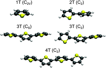 | ||
| Fig. 1 Optimized B3LYP/6-311G** ground state geometries of 1T–4T. For 3T both nearly isoenergetic minima are shown. The point groups of the structures are given in parentheses. | ||
At these geometries the low-lying ππ* and the πσ* singlet states plus the first four triplet states of 1T–4T were computed. The excitation energies, the electronic characters and oscillator strengths are listed in Table 1 together with the corresponding experimental data. To facilitate the comparison of the electronic states of the different systems, the HOMO of all molecules is denoted π1 and the LUMO π1* orbital (for details, see ESI†). When possible the calculations were performed on the CASPT2, CCSD and TDDFT levels of theory for comparison and we found a good agreement for all molecules studied. A complete list with the results of all methods used is given in Tables S1–S5 in the ESI.† Our focus is on the bright S1 state and its relaxation paths after optical excitation as this state is discussed to be crucial for the use of oligothiophenes in organic devices. The πσ* singlet state is responsible for a nonradiative relaxation via a ring opening path and the triplet states induce the ISC. The results in Table 1 are discussed from these aspects. In the FC region the S1 state has ππ* character and is completely delocalized for all investigated systems. The excitation energy of the S1 state decreases from 1T to 4T and its corresponding oscillator strength increases. The calculated vertical excitation energy of the S1 state agrees very well for 1T and 2T with the experimental values while for 3T and 4T larger deviations are observed. The use of larger basis sets reduces these deviations (see Tables S12, S13 and S16, ESI†). But the combination with the large active spaces required for 3T and 4T (see Section 3.2.4) cannot be handled within a reasonable computation time. The state order of the πσ* singlet state increases systematically from the S3 state in 1T to the S7 state in 4T as more and more ππ* states intrude (see Tables S1–S5 in the ESI†). The πσ* state is due to the σ* character more localized and does not profit as much as the ππ* states from the elongation of the π-system.
| 1T (C2v) | 2T (C2) | 3T (Cs) | 3T (C2) | 4T (C2) | |||||||||||||||
|---|---|---|---|---|---|---|---|---|---|---|---|---|---|---|---|---|---|---|---|
| State | Char. | CASPT2 | Exp. | State | Char. | CASPT2 | Exp. | State | Char. | CASPT2 | CCSD | State | CASPT2 | CCSD | Exp. | State | Char. | CCSD | Exp. |
| a Magnetic circular dichroism.11 b Electron energy loss spectroscopy.36 c Gas-phase absorption spectrum at room temperature.19 d Photodetachment photoelectron spectrum in the gas phase.47 e At the CASPT2 level of theory the S2 state of both the 3T conformers is described by an π2π1* excitation, while with the CCSD method the S2 state has π1π2* character and A′ and A symmetry, respectively, (see Tables S3 and S4 in the ESI). f Absorption spectrum in solution at room temperature.22,25,30 g Absorption spectrum in solution at room temperature.13,22,25 | |||||||||||||||||||
| S1(A1) | π2π1* | 5.58 (0.06) | 5.26a | S1(B) | π1π1* | 4.51 (0.45) | 4.29c | S1(A′′) | π1π1* | 4.03 (0.55) | 4.15 (0.79) | S1(B) | 4.08 (0.52) | 4.14 (0.77) | 3.5f | S1(B) | π1π1* | 4.00 (1.30) | 3.2g |
| S2(B2) | π1π1* | 5.92 (0.11) | 5.64a | S2(B) | π4π1* | 4.85 (0.14) | 5.08c | S2(A′′)e | π2π1* | 4.42 (0.06) | 4.97 (0.00) | S2(B) | 4.39 (0.08) | 4.98 (0.00) | — | S2(A) | π1π2* | 4.89 (0.00) | |
| S3(B1) | π1σ1* | 6.37 (0.00) | — | S5(A) | π1σ1* | 5.40 (0.00) | — | S6(A′) | π1σ1* | — | 5.46 (0.00) | S6(B) | — | 5.49 (0.00) | — | S7(B) | π1σ1* | 5.62 (0.00) | |
| T1(B2) | π1π1* | 3.76 | 3.74b | T1(B) | π1π1* | 2.86 | 2.32d | T1(A′′) | π1π1* | 2.40 | 2.56 | T1(B) | 2.42 | 2.56 | 1.90d | T1(B) | π1π1* | 2.36 | 1.75d |
| T2(A1) | π2π1* | 4.75 | 4.50b | T2(A) | π1π2* | 3.82 | — | T2(A′) | π1π2* | 3.19 | 3.38 | T2(A) | 3.17 | 3.36 | 2.99d | T2(A) | π1π2* | 3.00 | 2.56d |
| T3(B1) | π1σ1* | 6.11 | — | T3(A) | π3π1* | 4.41 | — | T3(A′′) | π1π3* | 3.85 | 4.07 | T3(B) | 3.87 | 4.08 | — | T3(B) | π1π3* | 3.64 | |
| T4(A2) | π2σ1* | 6.13 | — | T4(B) | π4π1* | 4.48 | — | T4(A′) | π3π1* | 4.30 | 4.41 | T4(A) | 4.29 | 4.39 | — | T4(A) | π2π1* | 4.16 | |
In 1T the T3 and T4 states have πσ* character and lie substantially above the S1 state. The energy gap to the T2 state with ππ* character is also large (0.83 eV). In 2T more ππ* states exist due to the extension of the system. T2 and T3 are such additional ππ* states and lie below the S1 state with a small S1–T3 energy gap of only 0.10 eV (see Table 1). The T4 state has comparable character to the T2 state of 1T and is nearly isoenergetic with the S1 state in agreement with a previous study.48 Also in the larger oligothiophenes the four lowest triplet states are characterized by ππ* excitations, whereby the T4 state becomes more localized for 3T and 4T and therewith shifts slightly above the S1 state. In 3T the S1 state is energetically close to the T3 state. At the CASPT2 level of theory only the inclusion of all π-orbitals in the active space results in the correct electronic state order consistent with the CCSD results. The use of a smaller active space leads to artificial stabilization of the S1 state with respect to the triplet states shifting it below the T3 state59 (see Table S11 in the ESI†). Also in 4T the S1 state is only slightly above the T3 state at the CCSD level of theory.
Of the studied molecules only 1T exhibits large singlet–triplet energy gaps at the FC point. In combination with the low-lying πσ* singlet state S3 this gives a first hint why photoexcited 1T decays primarily via singlet states and no intersystem crossing occurs.37,41–43 In contrast thereto, the oligothiophenes 2T–4T show small singlet–triplet energy gaps, which however increase with the chain length (0.03 eV for 2T, 0.18 eV (Cs) and 0.21 eV (C2) for 3T and 0.36 eV for 4T). This is consistent with the experimental observation of extremely high triplet quantum yields for the oligothiophenes, which however decrease again with size (0.99 for 2T, 0.95 for 3T and 0.73 for 4T).25 The details of the relaxation pathways of the different systems will be discussed in the next sections.
3.2 Deactivation pathways
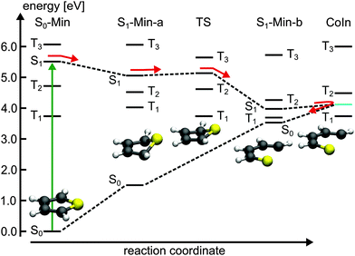
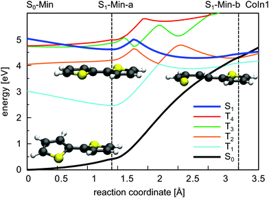
For 1T–3T all results are at the CASPT2 level of theory and when possible confirmed by CCSD calculations. For the larger 4T system the CCSD and TDDFT methods were used.So far the barrier height for the ring-opening from S1-Min-a to S1-Min-b was estimated by linear interpolation at the CCSD level of theory to be 0.26 eV and understood as a consequence of an avoided crossing.43 We were able to locate the transition state (TS) separating the two S1 minima at the CASPT2 level of theory (Fig. 2, for details, see Fig. S2 and Table S6 in the ESI†). Therewith the barrier height is reduced to 0.07 eV. We also found that the CoIn is part of a low lying and thus very efficient seam along the dSCCC dihedral angle (see Fig. S3 and S4 in the ESI†).
Salzmann et al.41 argued that due to vanishing spin–orbit coupling (SOC) and large S1–triplet energy gaps at the FC point and at S1-Min-a (see Fig. 2) a notable probability for ISC may only exist along the ring-opening path. However the ISC has to compete with the highly effective irreversible ring-opening path through the CoIn seam. Thus our additional results further support the interpretation that thiophene after excitation to the S1 state decays mainly via its singlet electronic states, which is consistent with the observed dynamics and the absence of fluorescence and phosphorescence.37
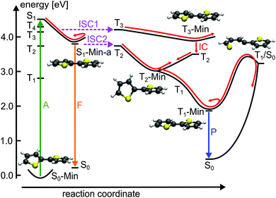
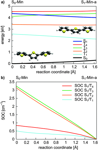
Triplet states and intersystem crossing. In 2T the triplet states T4 and T3 are below and close to the S1 state at the FC point. Optimization of the S1 state leads to the conversion of the non-planar structure to a planar minimum with C2h symmetry (S1-Min-a) and lowers its energy below the T4 and T3 states (see Table 2). We constructed a simplified reaction path RCS by linear interpolation between the optimized S0-Min and S1-Min-a geometries. The calculated energies along the RCS reveal the intersection of the S1 state with the T4 and T3 states (Fig. 3a).
| State | Character | S0-Min (C2) | S1-Min-a (C2h) | |||
|---|---|---|---|---|---|---|
| Sym. | CASPT2 | Sym. | CASPT2 | Exp. | ||
| a Maximum of the fluorescence spectrum in dioxane at room temperature.25 b Photodetachment photoelectron spectrum in the gas phase.47 | ||||||
| S1 | π1 → π1* | B | 4.51 (0.45) | B u | 3.71 (0.43) | 3.43a |
| S2 | π4 → π1* | B | 4.85 (0.14) | A g | 4.22 (0.00) | — |
| S5 | π1 → σ1* | A | 5.40 (0.00) | A u | 4.74 (0.00) | — |
| T1 | π1 → π1* | B | 2.86 | B u | 1.99 | 2.32b |
| T2 | π1 → π2* | A | 3.82 | A g | 3.57 | — |
| T3 | π3 → π1* | A | 4.41 | A g | 4.11 | — |
| T4 | π4 → π1* | B | 4.48 | B u | 4.26 | — |
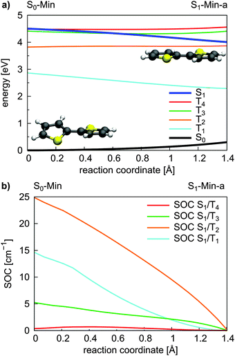 | ||
| Fig. 3 Energy profile of the S0, the S1 and the four lowest lying triplet states (a) and the SOC between the S1 and triplet states (b) along the S1 relaxation coordinate of 2T. The energy calculations were performed at the CASPT2/6-31G* level of theory and confirmed at the CCSD level (Fig. S9 in the ESI†). The SOCs were calculated using the CASSCF method. The reaction coordinate was generated by linear interpolation between the optimized S0-Min and S1-Min-a geometries. | ||
For an effective ISC between singlet and triplet states, the spin–orbit coupling (SOC) should be reasonably strong and the states involved should be close in energy. First semiempirical calculations using the INDO/SCI approach showed for 2T, 3T and 6T that the SOC values decay with decreasing torsion angle α.69 Since we are interested in the relaxation pathways from the S1 state, we calculated the SOC between the S1 and the four lowest lying triplet states along the reaction coordinate RCS at the CASSCF level (Fig. 3b).
All SOC values also decrease along this coordinate and vanish at S1-Min-a. Between S1 and T2/T3 the SOC is zero for symmetry reasons, between S1 and T1/T4 it vanishes, although the coupling is symmetry allowed. In general, for strong SOC, contributions from orbitals of heavy atoms have to be involved in the electronic configuration of the mixing states. The σ* orbital is localized on the S-atom and occurs via small πσ* contributions in the S1 state of 2T. This πσ* contribution systematically decays along the RCS as the planarization reduces the σ/π mixing. Correspondingly, all SOCs, also the symmetry allowed ones, decrease and vanish along this coordinate.
In view of the calculated SOC and the S1–triplet energy gaps, the highest ISC probability along the relaxation coordinate RCS exists with the T3 state. The intermediate degeneracy of the S1 and the T3 states should compensate for their moderate spin–orbit interaction and allow a fast ISC. An example for such a scenario has been shown recently for uracil by Richter et al.70 and has been discussed for benzene by Worth and co-workers.71,72
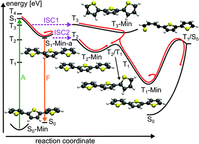
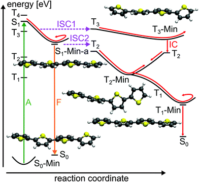
For the population that reaches S1-Min-a a second ISC path opens between the S1 and the T2 states (ISC2, see Fig. 4). Here both states are close in energy and although the SOC vanishes at the minimum geometry, the torsional out-of-plane motion can induce moderate coupling. Such motions have been shown to be highly active during the S1 dynamics of 2T–4T.45,46
The possibility of two ISC channels is consistent with the experimental observations of Paa et al.34 using femtosecond time-resolved spectroscopy. They obtained a biexponential decay for the transient S1 → Sn absorption (ESA) bands, with a fast (τ = 1.4 ps) and slow (τ = 29.6 ps) component. In addition the rise of the triplet–triplet absorption (TTA) is characterized by a fast time constant of 1.4 ps and a slower one of 58 ps. Therefore the authors proposed an ISC mechanism with two channels: the fast one starting from a twisted S1 state geometry and taking place during the initial geometry relaxation. The second slower ISC channel starts from the relaxed S1 state and competes with fluorescence from S1-Min-a. Although the oscillator strength is reasonable at S1-Min-a (see Table 2), the fluorescence quantum yield is reported to be small (ϕF = 0.014).25 Thus we suggest that the major part of the S1 population decays via the two ISC paths. The quantum yield ϕF of 2T is increased when the temperature is lowered from 298 to 77 K.25 Under these conditions the first ISC path is less populated as the lower temperature enhances the planarity of the ground state.25
Next we discuss the relaxation from T3 and T2 back to the ground state. The T3 relaxation leads to the planar T3 state minimum where the T3 and T2 states are close in energy (ΔE = 0.28 eV, see Table S8 in the ESI†). Therewith the T2 state can also be populated by a fast internal conversion from T3 (Fig. 4). T2 is the only state considered which is described by an excitation to the π2* orbital (see Table 2). This orbital is characterized by an antibonding π-interaction between the thiophene rings (see Fig. S5 in the ESI†), therefore the T2 minimum is a twisted structure with orthogonal thiophene rings (T2-Min, Fig. 4). At this minimum the T2 state is degenerate with the T1 state47 (see Table S8 in the ESI†) suggesting the existence of a T2/T1 CoIn from where relaxation into the global excited state minimum T1-Min (Fig. 4) can take place. The calculated vertical emission energy at this planar minimum is 1.77 eV and corresponds to the maximum of the phosphorescence spectrum (2.06 eV).32 Since the phosphorescence is weak (ϕP = 10−5),32 we conclude that by far most of the population return back to the ground state by a nonradiative process.25 This process will be discussed in combination with a possible decay via CoIns in the next section.
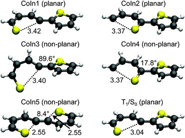
Conical intersections. A remaining question is why for 2T the deactivation path is dominated by ISC not by the ring-opening path via the S1/S0 CoIns which is the major path for 1T. We therefore optimized the S1/S0 CoIns and the S1-Min-b minima for 2T. For 1T only one open-chain structure with a broken C–S bond is distinguishable. For the trans conformation of 2T several open-chain structures are possible. First of all four singly and six doubly opened geometries can be discriminated. The singly opened structures can be planar or non-planar and the inner or the outer C–S bond can be broken. The four optimized CoIns are shown in Fig. 5 (CoIn1–4) and are as in 1T in the vicinity of the S1-Min-b minima. In all these structures the S1 state has πσ* character while the S0 state is the closed shell electronic configuration. The geometries of the CoIns1–4 and the S1-Min-b minima are quite similar to the corresponding ones of 1T, e.g. the distances of the broken C–S bonds are nearly identical (1T CoIn: 3.41 Å). Also the barrier from the S1-Min-b minima to the CoIns is at most 0.1 eV (Table 3) and mainly associated with a small elongation of the C–S bond (see Fig. S10 in the ESI†). CoIn1 and CoIn3 lie below and CoIn2 and CoIn4 above S1-Min-a (see Table 3). The cleavage of an outer C–S bond leads to steric repulsion between the sulfur atom and the adjacent thiophene ring (see Fig. 5) resulting in the destabilization of CoIn2 and CoIn4. The cleavage of the inner C–S bonds leads to a lower steric repulsion and explains the stabilization of CoIn1 (0.2 eV) and CoIn3 (0.4 eV), whereby CoIn3 is the lowest intersection due to the orthogonal position of the thiophene rings.
| CoIn1 | CoIn2 | CoIn3 | CoIn4 | CoIn5 | |
|---|---|---|---|---|---|
| S1-Min-b | 3.75 | 4.13 | 3.58 | 4.12 | — |
| Conical intersection | 3.85 | 4.22 | 3.60 | 4.20 | 4.09 |
| Stabilization energy | 0.16 | −0.21 | 0.41 | −0.19 | −0.08 |
| Barrier | 0.40 | 0.87 | 1.04 | 0.92 | — |
Based on these results we identified the most promising one of the six doubly opened geometries. The optimized non-planar structure CoIn5 (Fig. 5) shows that when two C–S bonds are broken the S1/S0 degeneracy is achieved already for smaller elongations of the C–S distance to 2.55 Å. Nevertheless CoIn5 lies above S1-Min-a (Table 3) and is further neglected.
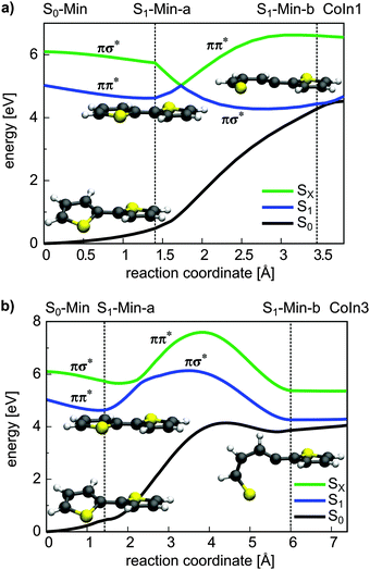
From the energetics at least CoIn1 and CoIn3 could be reached from S1-Min-a. But the possible barriers in between have to be considered. This was investigated again by using simplified reaction paths RCS2 constructed by linear interpolation between S1-Min-a, S1-Min-b and the respective CoIn. Based on the good agreement between CASPT2 and CCSD results obtained for the energy profile along the RCS (see Fig. 3a and Fig. S9 in the ESI†), we calculated the four continuing ring-opening paths RCS2 using the faster CCSD method. The single-reference method CCSD has previously been used to study the deactivation paths of thiophene43 and furan73 and was found to give energies of good quality even in the vicinity of CoIns. This is also found for the paths towards CoIn1/CoIn3 (Fig. 6) and CoIn2/CoIn4 (Fig. S11 in ESI†). The positions of the CoIns at the CCSD level are only slightly shifted with respect to the CASSCF results and thus the CCSD results are sufficiently accurate to estimate the barriers. The reported values for the barriers in Table 3 are an upper limit for the real ones. Optimization of the corresponding transition states would lower these barriers as shown for 1T (see Section 3.2.1). Nevertheless from the barrier heights one can see that CoIn1 is associated with the smallest barrier of 0.4 eV and the lowest CoIn (CoIn3) with a barrier of 1.0 eV. This can be understood as the geometrical distortion necessary to reach the non-planar CoIn3 from the planar S1-Min-a is significantly larger than from the planar CoIn1. This is also reflected in the larger RCS2 values for CoIn3 (Fig. 6b).
In summary, CoIn1 is the most favorable intersection of 2T and should be reachable due to an accumulated relaxation energy of 0.5 eV from the FC point to S1-Min-a. Thus some of the excited molecules should decay to the ground state through this passage. This is, however, in contrast to the measured near-unity triplet quantum yield of 2T. A possible explanation is that also along the ring-opening path to CoIn1 the S1 state can couple to the triplet states. We calculated the four lowest lying triplet states along this path and, indeed found several intersections between the S1 and the triplet states (Fig. 7). In addition near and after the barrier strong SOC of the S1 state with the triplet states occur (≈20–100 cm−1, Table S9 in the ESI†) due to the rising πσ* character of the S1 state.
The results clearly elucidate why the deactivation path of 2T is dominated by ISC and the relaxation path of 1T by S1/S0 CoIns. First of all after excitation to the S1 state only for 2T effective ISC possibilities exist during the initial motion (compare Fig. 2 and 3). Secondly the barrier to reach a CoIn is higher for 2T (0.40 eV) than for 1T (0.26 eV). And finally even if the barrier to the S1/S0 CoIn is overcome, the ISC to several triplet states is probable in 2T and depopulates the S1 state.
The calculations along the ring-opening path RCS2 (Fig. 7) also reveal the existence of a low lying intersection between the T1 and the S0 state. The optimized T1/S0 intersection is a planar structure with a broken C–S bond of 3.04 Å (Fig. 5) where the T1 state has πσ* character and accordingly large SOC values with the S0 state (≈100 cm−1). This intersection found along the ring-opening path could also be responsible for the overall relaxation from the triplets back to the ground state. We therefore estimated the barrier from the endpoint of the triplet cascade, T1-Min, to the T1/S0 intersection by linear interpolation at the CASPT2 level of theory (Fig. S12 in the ESI†). The calculated barrier height of 1.39 eV should account for the long triplet lifetime of 100 μs of 2T.25 The reaction coordinate of this path is mainly characterized by an elongation of the C–S distance. As the gradient difference vector at the T1/S0 intersection is nearly orthogonal to this reaction coordinate (Fig. S10, ESI†), the probability for intersystem crossing is quite high after the system has crossed the barrier (for details, see ESI†). All in all the T1/S0 intersection completes the deactivation pathway of 2T.
| State | Character | S0-Min (Cs) | S1-Min-a (C2v) | |||
|---|---|---|---|---|---|---|
| Sym. | CASPT2 | Sym. | CASPT2 | Exp. | ||
| a Maximum of the fluorescence spectrum in dioxane at room temperature.25 b At S1-Min-a the S2 state is described by an double excitation (π1 ⇉ π1*). c Photodetachment photoelectron spectrum in the gas phase.47 | ||||||
| S1 | π1 → π1* | A′′ | 4.03 (0.55) | B 1 | 3.08 (0.68) | 2.91a |
| S2 | π2 → π1* | A′′ | 4.42 (0.06) | A 1 | 3.56 (0.00) | — |
| T1 | π1 → π1* | A′′ | 2.40 | B 1 | 1.75 | 1.90c |
| T2 | π1 → π2* | A′ | 3.19 | A 1 | 2.87 | 2.99c |
| T3 | π1 → π3* | A′′ | 3.85 | B 1 | 3.81 | — |
| T4 | π3 → π1* | A′ | 4.30 | A 1 | 4.19 | — |
Also for 3T both ISC channels are confirmed by experimental results. Beyond that the experimental observations can now be understood more deeply. Rentsch and co-workers carried out femtosecond time-resolved spectroscopy with dependence on the excitation wavelength.28,33,34 They observed a biexponential decay for the S1 state with a fast and slow component occurring in parallel with the triplet formation. Both processes and the triplet quantum yield were found to depend on the excitation energy. At a wavelength of 400 nm (low-energy side of the S0 → S1 absorption band) the S1 decay and the rise of the TTA are determined by the fluorescence lifetime of the S1 state (165 ps).34 With increasing excitation energies an additional fast channel for triplet formation with a time constant of about 2 ps occurs. The triplet quantum yield reaches a maximum value at 381 nm and remains constant up to 370 nm. Rentsch and co-workers suggested that the fast ISC channel is populated by excitation of non-planar molecules and opens while the planar S1-Min-a is approached. With the low energy pulse mainly planar molecules are excited among the ensemble as the planar conformation has the lowest excitation energy.74 The fast ISC channel is considered to be responsible for the highly effective triplet formation and has been quantified by temperature dependent measurements of the fluorescence quantum yield by Rossi et al.75 They estimated that more than half of the T1 population of 3T arises from this channel. The details of the two ISC channels are clearly elucidated by the results of the present work. Only if non-planar conformations are excited the fast ISC from the S1 state to the T3 state can happen. If planar conformations are excited thermal torsional vibrational activity can induce the second ISC from the S1 to the T2 state.
Like in 2T a remaining question is the possible role of S1/S0 CoIns as deactivation path. Based on the results of 2T we focused on the most promising one and optimized a planar S1/S0 conical intersection with a singly broken C–S bond. We also located the corresponding S1 minimum (S1-Min-b), which was found again in the vicinity of the CoIn. The barrier between S1-Min-a and S1-Min-b was estimated by linear interpolation at the CCSD/6-31G* level of theory (see Fig. S20 in the ESI†). The optimized CoIn geometry (Fig. 10) is similar to the ones of the smaller systems, only the C–S distance (3.69 Å) is slightly larger than in 2T (3.42 Å) and 1T (3.41 Å).
In Table 5 the relevant points of the pathway to the CoIns are compared for 1T–3T. The adiabatic energy difference in the CoIns stays in the same range while the S1 (ππ*) state is significantly stabilized at the FC point and at S1-Min-a due to the increased π system. At the CoIns the S1 state has πσ* character and is thus more localized and does not profit to the same extent from the elongation of the π-system. The significant lowering of the ππ* relative to the πσ* character in the S1 state is also reflected by the increased barrier between S1-Min-a and S1-Min-b from 1T to 3T inhibiting the passage to the S1/S0 CoIn for the oligothiophenes. The higher barrier for 3T relative to 2T is confirmed by the even smaller rate constant for internal conversion.25 The low barrier for 1T can be further understood comparing the structures of the S1-Min-a minima. Only in 1T it is non-planar (Fig. 2) and the C–S bond is already slightly elongated in comparison to S0-Min. Thus in 1T the initial relaxation is directed towards the ring-opening while the initial relaxation of 2T and 3T is characterized by inter-ring rotation leading to planar geometries.
| 1T | 2T | 3T | |
|---|---|---|---|
| FC point | 5.58 | 4.51 | 4.03 |
| S1-Min-a | 5.07 | 4.01 | 3.27 |
| S1-Min-b | 4.00 | 3.75 | 4.16 |
| Conical intersection | 4.08 | 3.85 | 4.32 |
| Barrier | 0.26 | 0.40 | 0.81 |
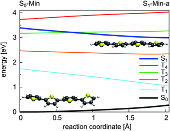
From the planar S1-Min-a the ring-opening path is thus highly unlikely for 3T. Even if the high barrier is overcome, several intersections of the S1 state with the triplet states (see Fig. S20 in the ESI†) with strong SOC (≈20–100 cm−1, Table S15 in the ESI†) exist and would again induce ISC. Another deactivation possibility out of S1-Min-a is fluorescence. The S1 state has a reasonable oscillator strength and the calculated vertical energy compares well with the maximum of the fluorescence spectrum (see Table 4). The higher fluorescence quantum yield of 3T (ϕF = 0.054) in comparison to 2T (ϕF = 0.024)25 can be explained by the lower SOC values along the initial relaxation towards S1-Min-a and the higher barrier for the ring-opening path. Still the major part of the S1 population decays via ISC.
The depopulation pathways of the triplet states proceeds again via a cascade. Relaxation of the T3 state leads to its minimum. Like the T2 state of 2T the T3 state of 3T is described by an excitation to an antibonding π-orbital (π3*, Table 4) with nodal planes between the thiophene rings (see Fig. S14 in the ESI†). Accordingly, the T3 minimum is a twisted structure with orthogonal thiophene rings (T3-Min, Fig. 9). At this minimum the first three triplet states are close in energy (see Table S14 in the ESI†) and a fast internal conversion from T3 to T2 or T1 can happen. The T2 minimum is planar (T2-Min, Fig. 9) and in contrast to the non-planar T2-Min of 2T now an energy gap of 0.76 exists between T2 and T1 and a barrier of 0.32 eV has to be overcome to reach the T2/T1 conical intersection. The T2/T1 conical intersection is characterized by one terminal thiophene ring being orthogonal to two planar thiophene rings (Fig. 9). In T1 the global excited state minimum is reached, which is again planar (Fig. 9). As no phosphorescence was detected,25 a possible relaxation back to the ground state is again via the T1/S0 intersection with one broken C–S bond (Fig. 10). We estimated again the barrier between T1-Min and T1/S0 by interpolation at the CCSD level of theory. The high value of 2.17 eV to reach this intersection could account for the long triplet lifetime of 3T.25 But after crossing this barrier, the probability for intersystem crossing is quite high like in 2T (for details, see ESI†).
| State | Character | S0-Min (C2) | S1-Min-a (C2h) | |||
|---|---|---|---|---|---|---|
| Sym. | CCSD | Sym. | CCSD | Exp. | ||
| a Maximum of the fluorescence spectrum in dioxane at room temperature.25 b Photodetachment photoelectron spectrum in the gas phase.47 | ||||||
| S1 | π1 → π1* | B | 4.00 (1.30) | B u | 3.30 (1.40) | 2.59a |
| S2 | π1 → π2* | A | 4.89 (0.00) | A g | 4.40 (0.00) | — |
| T1 | π1 → π1* | B | 2.36 | B u | 1.59 | 1.75b |
| T2 | π1 → π2* | A | 3.00 | A g | 2.58 | 2.56b |
| T3 | π1 → π3* | B | 3.64 | B u | 3.44 | — |
| T4 | π2 → π1* | A | 4.16 | A g | 4.14 | — |
Our conclusions are supported by the slow (390 ps) and fast (36 ps) time constants measured for the decay of the fluorescence of 4T.27 For comparison the fast time constant for this signal is found to be 16 ps for 3T while for the fast ESA decay and TTA rise it was 2 ps. The 390 ps time constant coincides well with the recently determined time constant for the TTA rise of 398 ps of 4T.40 In addition a biexponential triplet formation was mentioned for 4T.31 We assume that the fast ISC channel of 4T has not been observed until now as no femtosecond time-resolved measurements with dependence on the excitation wavelength were performed similar to 3T. Based on the presented results we suggest that also in 4T the fast ISC to the T3 state accounts for the high triplet quantum yield of 0.73.25 Reasons for the decreasing triplet quantum yield from 2T to 4T are the diminishing SOC values along the initial relaxation (ISC1) and the increasing S1–T2 energy gap at S1-Min-a (ISC2) (see Table S18 in the ESI†), also shown by photodetachment photoelectron spectroscopy.47
The return from the triplets back to the ground state involves similar steps as in 2T. T3 relaxation leads to its minimum where the outer thiophene rings are twisted versus the two planar inner rings (Fig. 12) due to the π3*-orbital (Table 6) characterizing nonbonding and bonding interactions between the thiophene rings (see Fig. S23 in the ESI†). The moderate T3–T2 energy gap of 0.41 eV at T3-Min suggests the possibility of an internal conversion to T2. From there the T2 minimum can be reached characterized by an orthogonal arrangement of the thiophene rings with respect to the central bond (Fig. 12) due to the π2* orbital (see Fig. S23 in the ESI†). At T2-Min the T2 and T1 states are degenerated like in 2T (see Table S17 in ESI†), leading to fast internal conversion to T1. In T1 the global excited state minimum is reached, which is again planar (see Fig. 12). As no phosphorescence was detected,25 an ISC like in 2T and 3T should lead the molecule back to the ground state. The smaller T1–S0 energy gap of 1.0 eV (CCSD/6-31G* level) at the T1-Min in comparison to 3T (1.42 eV) and 2T (1.77) could account for the decreasing triplet lifetime from 2T to 4T.25 Although the fluorescence from S1 is increased compared to 2T and 3T,25 the major part of the 4T population still relaxes to the ground state via ISC and triplet states.
4 Conclusions
For thiophene 1T and the oligothiophenes 2T–4T the relaxation processes from the first excited singlet state were investigated using quantum chemical calculations. We demonstrated that 1T decays primarily via its singlet states. Due to large singlet–triplet energy gaps intersystem crossing (ISC) is ineffective, while internal conversion via a low lying S1/S0 conical intersection (CoIn) seam is associated with a very small barrier and thus highly efficient. In contrast the deactivation paths of the oligothiophenes are dominated by ISC. The S1/S0 CoIns are inactive although their energetic position with respect to the ground state minimum is similar for all systems. However, the excited S1 state is significantly stabilized with increasing chain length due to its ππ* character in the Franck–Condon (FC) region and at the S1 minimum (S1-Min-a). At the S1/S0 CoIns the S1 state character has changed to πσ* which is more localized and does not profit to the same extent from the elongation of the π-system. Thus in the oligothiophenes the barriers towards the CoIns are increased and inhibit the passage through them. Furthermore the extension of the π-system induces more ππ* states and shifts the triplet state T3 below and close to the S1 state at the FC point for all investigated oligothiophenes. During the initial relaxation from the non-planar conformation to the planar S1-Min-a the T3 state intersects with the S1 state opening the first ISC path. Around S1-Min-a thermal torsional fluctuations can induce the second, less effective ISC channel with the T2 state. In view of the experimental findings and our results, we conclude that the first ISC channel is responsible for the high triplet quantum yields. Hereby we can say that the correlation between the planarization and the ISC is the key property. The overall diminishing SOC from 2T to 4T and the increasing S1–T2 energy gaps at S1-Min-a should account for the slightly decreasing triplet and increasing fluorescence quantum yields.25 A quantitative determination of the rate constants and branching ratios of the two ISC channels would require dynamical studies but these are clearly beyond the scope of the present work. The return from the triplets back to the ground state is made possible by inter-ring torsions and T1/S0 intersections, the latter are characterized by open-ring structures similar to the S1/S0 CoIns of 1T. We found two different kinds of triplet relaxation. For the even-numbered oligothiophenes we found a T3 → T2 → T1 cascade, while for the odd oligothiophene an additional direct T3 → T1 path exists.The present results in combination with previous theoretical and experimental observations offer a quite complete picture of the photophysics of 1T–4T and allow making predictions for the longer oligothiophenes. Also for the longer oligothiophenes and polythiophenes triplet formation has been observed.25,76–79 From our results for 2T–4T we extrapolate that the first ISC path should be present as well and non-planarity should enhance its efficiency. Preliminary calculations for 5T–10T show, with the exception of 6T, an intersection of the S1 state with a triplet state along the planarization to S1-Min-a (see Tables S19 and S20 in the ESI†). The special behavior of 6T is consistent with its highest fluorescence quantum yield (ϕF) in the row from 2T to 7T.25 Furthermore for polythiophenes in solution and films it was shown that ϕF decreases due to more efficient nonradiative decay channels when the non-planarity of the thiophene backbone is increased by substitution.80 The higher degree of non-planarity should enhance the SOC and prolong the interaction time for the ISC. As triplet states are also present in polythiophene-based solar cells81,82 a deeper understanding of the relaxation processes and the factors influencing the efficiency of these processes should be a first step in improving the performance of the thiophene-based devices.
Acknowledgements
Financial support of this work from the Deutsche Forschungsgemeinschaft through the SFB749 and the excellence cluster ‘Munich-Centre for Advanced Photonics’ (MAP) is gratefully acknowledged. We thank Alexander André and Moritz Hönig for their contribution to the initial calculations of 1T and 2T.References
- Handbook of Conducting Polymers, ed. T. A. Skotheim and J. R. Reynolds, CRC Press, Boca Raton, FL, 3rd edn, 2007 Search PubMed.
- Handbook of Thiophene-Based Materials: Applications in Organic Electronics and Photonics, ed. I. F. Perepichka and D. F. Perepichka, John Wiley & Sons Ltd, Chichester, UK, 2007 Search PubMed.
- B. L. Rupert, W. J. Mitchell, A. J. Ferguson, M. E. Köse, W. L. Rance, G. Rumbles, D. S. Ginley, S. E. Shaheen and N. Kopidakis, J. Mater. Chem., 2009, 19, 5311–5324 RSC.
- F. Zhang, D. Wu, Y. Xu and X. Feng, J. Mater. Chem., 2011, 21, 17590–17600 RSC.
- G. Gigli, O. InganKäs, M. Anni, M. De Vittorio, R. Cingolani, G. Barbarella and L. Favaretto, Appl. Phys. Lett., 2001, 78, 1493–1495 CrossRef CAS.
- M. Mazzeo, D. Pisignano, L. Favaretto, G. Barbarella, R. Cingolani and G. Gigli, Synth. Met., 2003, 139, 671–673 CrossRef CAS.
- M. Irie, T. Fukaminato, K. Matsuda and S. Kobatake, Chem. Rev., 2014, 114, 12174–12277 CrossRef CAS PubMed.
- G. Barbarella, M. Zambianchi, A. Ventola, E. Fabiano, F. Della Sala, G. Gigli, M. Anni, A. Bolognesi, L. Polito, M. Naldi and M. Capobianco, Bioconjugate Chem., 2006, 17, 58–67 CrossRef CAS PubMed.
- H.-A. Ho, A. Najari and M. Leclerc, Acc. Chem. Res., 2008, 41, 168–178 CrossRef CAS PubMed.
- M. Zambianchi, F. D. Maria, A. Cazzato, G. Gigli, M. Piacenza, F. D. Sala and G. Barbarella, J. Am. Chem. Soc., 2009, 131, 10892–10900 CrossRef CAS PubMed.
- R. Håkansson, B. Nordén and E. W. Thulstrup, Chem. Phys. Lett., 1977, 50, 306–308 CrossRef.
- D. Birnbaum and B. E. Kohler, J. Chem. Phys., 1989, 90, 3506–3510 CrossRef CAS.
- H. Chosrovian, S. Rentsch, D. Grebner, D. Dahm, E. Birckner and H. Naarmann, Synth. Met., 1993, 60, 23–26 CrossRef CAS.
- D. Lap, D. Grebner, S. Rentsch and H. Naarmann, Chem. Phys. Lett., 1993, 211, 135–139 CrossRef CAS.
- R. Rossi, M. Ciofalo and P. Glauco, J. Photochem. Photobiol., A, 1993, 70, 59–67 CrossRef CAS.
- S. Yamaguchi and H.-o. Hamaguchi, Chem. Phys. Lett., 1994, 227, 255–260 CrossRef CAS.
- J. E. Chadwick and B. E. Kohler, J. Phys. Chem., 1994, 98, 3631–3637 CrossRef CAS.
- W. J. Buma, B. E. Kohler and T. A. Shaler, J. Phys. Chem., 1994, 98, 4990–4992 CrossRef CAS.
- M. Belletête, M. Leclerc and G. Durocher, J. Phys. Chem., 1994, 98, 9450–9456 CrossRef.
- R. Colditz, D. Grebner, M. Helbig and S. Rentsch, Chem. Phys., 1995, 201, 309–320 CrossRef CAS.
- R. S. Becker, J. Seixas de Melo, A. L. Maçanita and F. Elisei, Pure Appl. Chem., 1995, 67, 9–16 CrossRef CAS.
- D. Grebner, M. Helbig and S. Rentsch, J. Phys. Chem., 1995, 99, 16991–16998 CrossRef CAS.
- G. Lanzani, M. Nisoli, S. De Silvestri and R. Tubino, Chem. Phys. Lett., 1996, 251, 339–345 CrossRef CAS.
- P. Landwehr, H. Port and H. Wolf, Chem. Phys. Lett., 1996, 260, 125–129 CrossRef CAS.
- R. S. Becker, J. Seixas de Melo, A. L. Maçanita and F. Elisei, J. Phys. Chem., 1996, 100, 18683–18695 CrossRef CAS.
- D. V. Lap, D. Grebner and S. Rentsch, J. Phys. Chem. A, 1997, 101, 107–112 CrossRef CAS.
- A. Yang, M. Kuroda, Y. Shiraishi and T. Kobayashi, J. Phys. Chem. B, 1998, 102, 3706–3711 CrossRef CAS.
- W. Paa, J.-P. Yang, M. Helbig, J. Hein and S. Rentsch, Chem. Phys. Lett., 1998, 292, 607–614 CrossRef CAS.
- N. DiCésare, M. Belletête, M. Leclerc and G. Durocher, Chem. Phys. Lett., 1998, 291, 487–495 CrossRef.
- N. DiCésare, M. Belletête, C. Marrano, M. Leclerc and G. Durocher, J. Phys. Chem. A, 1999, 103, 795–802 CrossRef.
- J. Yang, W. Paa and S. Rentsch, Synth. Met., 1999, 101, 624–625 CrossRef CAS.
- S. Rentsch, J. P. Yang, W. Paa, E. Birckner, J. Schiedt and R. Weinkauf, Phys. Chem. Chem. Phys., 1999, 1, 1707–1714 RSC.
- J.-P. Yang, W. Paa and S. Rentsch, Chem. Phys. Lett., 2000, 320, 665–672 CrossRef CAS.
- W. Paa, J.-P. Yang and S. Rentsch, Appl. Phys. B: Lasers Opt., 2000, 71, 443–449 CrossRef CAS.
- W. Paa, J.-P. Yang and S. Rentsch, Synth. Met., 2001, 119, 525–526 CrossRef CAS.
- H. Haberkern, K. R. Asmis, M. Allan and P. Swiderek, Phys. Chem. Chem. Phys., 2003, 5, 827–833 RSC.
- R. Weinkauf, L. Lehr, E. W. Schlag, S. Salzmann and C. M. Marian, Phys. Chem. Chem. Phys., 2008, 10, 393–404 RSC.
- D. M. P. Holland, A. B. Trofimov, E. A. Seddon, E. V. Gromov, T. Korona, N. de Oliveira, L. E. Archer, D. Joyeux and L. Nahon, Phys. Chem. Chem. Phys., 2014, 16, 21629–21644 RSC.
- J. Zhou, W. Yu and A. E. Bragg, J. Phys. Chem. Lett., 2015, 6, 3496–3502 CrossRef CAS PubMed.
- S.-m. Sun, S. Zhang, K. Liu, Y.-p. Wang and B. Zhang, Photochem. Photobiol. Sci., 2015, 14, 853–858 CAS.
- S. Salzmann, M. Kleinschmidt, J. Tatchen, R. Weinkauf and C. M. Marian, Phys. Chem. Chem. Phys., 2008, 10, 380–392 RSC.
- X.-F. Wu, X. Zheng, H.-G. Wang, Y.-Y. Zhao, X. Guan, D. L. Phillips, X. Chen and W. Fang, J. Chem. Phys., 2010, 133, 134507 CrossRef PubMed.
- M. Stenrup, Chem. Phys., 2012, 397, 18–25 CrossRef CAS.
- G. Cui and W. Fang, J. Phys. Chem. A, 2011, 115, 11544–11550 CrossRef CAS PubMed.
- D. Fazzi, M. Barbatti and W. Thiel, Phys. Chem. Chem. Phys., 2015, 17, 7787–7799 RSC.
- A. Prlj, B. F. E. Curchod and C. Corminboeuf, Phys. Chem. Chem. Phys., 2015, 17, 14719–14730 RSC.
- S. Siegert, F. Vogeler, C. M. Marian and R. Weinkauf, Phys. Chem. Chem. Phys., 2011, 13, 10350–10363 RSC.
- M. Rubio, M. Merchán, R. Pou-Amérigo and E. Ortí, ChemPhysChem, 2003, 4, 1308–1315 CrossRef CAS PubMed.
- S. H. Vosko, L. Wilk and M. Nusair, Can. J. Phys., 1980, 58, 1200–1211 CrossRef CAS.
- C. Lee, W. Yang and R. G. Parr, Phys. Rev. B: Condens. Matter Mater. Phys., 1988, 37, 785–789 CrossRef CAS.
- P. J. Stephens, F. J. Devlin, C. F. Chabalowski and M. J. Frisch, J. Phys. Chem., 1994, 98, 11623–11627 CrossRef CAS.
- A. D. Becke, J. Chem. Phys., 1993, 98, 5648–5652 CrossRef CAS.
- R. Krishnan, J. S. Binkley, R. Seeger and J. A. Pople, J. Chem. Phys., 1980, 72, 650–654 CrossRef CAS.
- H. A. Duarte, H. F. Dos Santos, W. R. Rocha and W. B. De Almeida, J. Chem. Phys., 2000, 113, 4206–4215 CrossRef CAS.
- P. Celani and H.-J. Werner, J. Chem. Phys., 2000, 112, 5546–5557 CrossRef CAS.
- J. F. Stanton and R. J. Bartlett, J. Chem. Phys., 1993, 98, 7029–7039 CrossRef CAS.
- T. Yanai, D. P. Tew and N. C. Handy, Chem. Phys. Lett., 2004, 393, 51–57 CrossRef CAS.
- M. M. Francl, W. J. Pietro, W. J. Hehre, J. S. Binkley, M. S. Gordon, D. J. DeFrees and J. A. Pople, J. Chem. Phys., 1982, 77, 3654–3665 CrossRef CAS.
- M. Rubio, M. Merchán and E. Ortí, ChemPhysChem, 2005, 6, 1357–1368 CrossRef CAS PubMed.
- M. Merchán, L. Serrano-Andrés, M. A. Robb and L. Blancafort, J. Am. Chem. Soc., 2005, 127, 1820–1825 CrossRef PubMed.
- A. Berning, M. Schweizer, H.-J. Werner, P. J. Knowles and P. Palmieri, Mol. Phys., 2000, 98, 1823–1833 CrossRef CAS.
- H.-J. Werner, P. J. Knowles, G. Knizia, F. R. Manby and M. Schütz, Wiley Interdiscip. Rev.: Comput. Mol. Sci., 2012, 2, 242–253 CrossRef CAS.
- H.-J. Werner, P. J. Knowles, G. Knizia, F. R. Manby, M. Schütz, P. Celani, T. Korona, R. Lindh, A. Mitrushenkov, G. Rauhut, K. R. Shamasundar, T. B. Adler, R. D. Amos, A. Bernhardsson, A. Berning, D. L. Cooper, M. J. O. Deegan, A. J. Dobbyn, F. Eckert, E. Goll, C. Hampel, A. Hesselmann, G. Hetzer, T. Hrenar, G. Jansen, C. Köppl, Y. Liu, A. W. Lloyd, R. A. Mata, A. J. May, S. J. McNicholas, W. Meyer, M. E. Mura, A. Nicklass, D. P. O'Neill, P. Palmieri, D. Peng, K. Pflüger, R. Pitzer, M. Reiher, T. Shiozaki, H. Stoll, A. J. Stone, R. Tarroni, T. Thorsteinsson and M. Wang, MOLPRO, version 2012.1, a package of ab initio programs, 2012, see http://www.molpro.net/ Search PubMed.
- M. J. Frisch, G. W. Trucks, H. B. Schlegel, G. E. Scuseria, M. A. Robb, J. R. Cheeseman, G. Scalmani, V. Barone, B. Mennucci, G. A. Petersson, H. Nakatsuji, M. Caricato, X. Li, H. P. Hratchian, A. F. Izmaylov, J. Bloino, G. Zheng, J. L. Sonnenberg, M. Hada, M. Ehara, K. Toyota, R. Fukuda, J. Hasegawa, M. Ishida, T. Nakajima, Y. Honda, O. Kitao, H. Nakai, T. Vreven, J. A. Montgomery, Jr., J. E. Peralta, F. Ogliaro, M. Bearpark, J. J. Heyd, E. Brothers, K. N. Kudin, V. N. Staroverov, R. Kobayashi, J. Normand, K. Raghavachari, A. Rendell, J. C. Burant, S. S. Iyengar, J. Tomasi, M. Cossi, N. Rega, J. M. Millam, M. Klene, J. E. Knox, J. B. Cross, V. Bakken, C. Adamo, J. Jaramillo, R. Gomperts, R. E. Stratmann, O. Yazyev, A. J. Austin, R. Cammi, C. Pomelli, J. W. Ochterski, R. L. Martin, K. Morokuma, V. G. Zakrzewski, G. A. Voth, P. Salvador, J. J. Dannenberg, S. Dapprich, A. D. Daniels, Ö. Farkas, J. B. Foresman, J. V. Ortiz, J. Cioslowski and D. J. Fox, Gaussian 09, Revision D.01, Gaussian Inc., Wallingford, CT, 2009 Search PubMed.
- M. Ciofalo and G. L. Manna, Chem. Phys. Lett., 1996, 263, 73–78 CrossRef CAS.
- S. Millefiori, A. Alparone and A. Millefiori, J. Heterocycl. Chem., 2000, 37, 847–853 CrossRef CAS.
- F. Liu, P. Zuo, L. Meng and S. J. Zheng, THEOCHEM, 2005, 726, 161–169 CrossRef CAS.
- G. Zerbi, B. Chierichetti and O. Ingänas, J. Chem. Phys., 1991, 94, 4637–4645 CrossRef.
- D. Beljonne, Z. Shuai, G. Pourtois and J. L. Bredas, J. Phys. Chem. A, 2001, 105, 3899–3907 CrossRef CAS.
- M. Richter, P. Marquetand, J. González-Vázquez, I. Sola and L. González, J. Phys. Chem. Lett., 2012, 3, 3090–3095 CrossRef CAS PubMed.
- D. Parker, R. Minns, T. Penfold, G. Worth and H. Fielding, Chem. Phys. Lett., 2009, 469, 43–47 CrossRef CAS.
- T. Penfold and G. Worth, Chem. Phys., 2010, 375, 58–66 CrossRef CAS.
- M. Stenrup and A. Larson, Chem. Phys., 2011, 379, 6–12 CrossRef CAS.
- M. Breza, V. Lukeš and I. Vrábel, THEOCHEM, 2001, 572, 151–160 CrossRef CAS.
- W. Porzio, S. Destri, M. Mascherpa, S. Rossini and S. Brückner, Synth. Met., 1993, 55, 408–413 CrossRef CAS.
- B. Kraabel, D. Moses and A. J. Heeger, J. Chem. Phys., 1995, 103, 5102 CrossRef CAS.
- H. Burrows, J. Seixas de Melo, C. Serpa, L. Arnaut, M. G. Miguel, A. Monkman, I. Hamblett and S. Navaratnam, Chem. Phys., 2002, 285, 3–11 CrossRef CAS.
- S. Cook, A. Furube and R. Katoh, Energy Environ. Sci., 2008, 1, 294 CAS.
- D. Sahoo, Y. Tian, G. Sforazzini, H. L. Anderson and I. G. Scheblykin, J. Mater. Chem. C, 2014, 2, 6601 RSC.
- M. Theander, O. Inganäs, W. Mammo, T. Olinga, M. Svensson and M. R. Andersson, J. Phys. Chem. B, 1999, 103, 7771–7780 CrossRef CAS.
- Z. Xu and B. Hu, Adv. Funct. Mater., 2008, 18, 2611–2617 CrossRef CAS.
- M. Liedtke, A. Sperlich, H. Kraus, A. Baumann, C. Deibel, M. J. M. Wirix, J. Loos, C. M. Cardona and V. Dyakonov, J. Am. Chem. Soc., 2011, 133, 9088–9094 CrossRef CAS PubMed.
Footnote |
| † Electronic supplementary information (ESI) available: Complete computational results and optimized geometries: Tables S1–S20 and Fig. S1–S23. See DOI: 10.1039/c5cp07634j |
| This journal is © the Owner Societies 2016 |


