
 Open Access Article
 This Open Access Article is licensed under a
 Creative Commons Attribution 3.0 Unported Licence
Connecting defects and amorphization in UiO-66 and MIL-140 metal–organic frameworks: a combined experimental and computational study†
Thomas D.
Bennett
*a,
Tanya K.
Todorova
b,
Emma F.
Baxter
a,
David G.
Reid
c,
Christel
Gervais
d,
Bart
Bueken
e,
B.
Van de Voorde
e,
Dirk
De Vos
e,
David A.
Keen
f and
Caroline
Mellot-Draznieks
*b
aDepartment of Materials Science and Metallurgy, University of Cambridge, Cambridge CB3 0FS, UK. E-mail: tdb35@cam.ac.uk
bLaboratoire de Chimie des Processus Biologiques, UMR 8229 CNRS, UPMC Univ Paris 06, Collège de France, 11 Place Marcelin Berthelot, 11 Marcelin Berthelot, 75231 Paris Cedex 05, France. E-mail: caroline.mellot-draznieks@college-de-france.fr
cDepartment of Chemistry, University of Cambridge, Lensfield Road, Cambridge, CB2 1EW, UK
dSorbonne Universités, UPMC Univ Paris 06, CNRS, Collège de France, UMR 7574, Chimie de la Matière Condensée de Paris, Paris, France
eCentre for Surface Chemistry and Catalysis, Leuven Chem&Tech, KULeuven, Celestijnenlaan 200F, P. O. Box 2461, 3001 Heverlee, Belgium
fISIS Facility, Rutherford Appleton Laboratory, Harwell Oxford, Didcot, Oxfordshire OX11 0QX, UK
First published on 2nd December 2015
Abstract
The mechanism and products of the structural collapse of the metal–organic frameworks (MOFs) UiO-66, MIL-140B and MIL-140C upon ball-milling are investigated through solid state 13C NMR and pair distribution function (PDF) studies, finding amorphization to proceed by the breaking of a fraction of metal–ligand bonding in each case. The amorphous products contain inorganic–organic bonding motifs reminiscent of the crystalline phases. Whilst the inorganic Zr6O4(OH)4 clusters of UiO-66 remain intact upon structural collapse, the ZrO backbone of the MIL-140 frameworks undergoes substantial distortion. Density functional theory calculations have been performed to investigate defective models of MIL-140B and show, through comparison of calculated and experimental 13C NMR spectra, that amorphization and defects in the materials are linked.
Introduction
Crystalline metal–organic frameworks (MOFs) continue to be of interest to the scientific community due to their high surface areas and related potential for gas sorption, separations, drug delivery and catalysis.1,2 Comparatively little attention is however focused on their amorphous counterparts, i.e. those which do not exhibit long range crystallographic order, yet still consist of three-dimensional arrays of connected inorganic nodes and organic ligands.3–5 The use of pressure, temperature or shear stress to induce transitions between crystalline and amorphous states is of particular intrigue,6–8 due to possible uses in reversible sorption, conductive and multiferroic applications.9 Whilst computational or experimental characterization of purely inorganic10 or organic11 amorphous frameworks is known, structural insight into amorphous MOFs (aMOFs) is largely limited to those which adopt similar network topologies to the zeolite family.12Mechanochemistry, or ball-milling is increasingly utilized to synthesize crystalline MOFs in relatively large quantities with minimal solvent use.13 Curiously, and unlike inorganic porous materials, MOFs are highly susceptible to collapse using the same treatment.14 Whilst this can be mitigated by pore-filling prior to treatment, it remains problematic given the use of ball-milling as a common post-processing method to increase external surface area.15,16 This propensity for collapse has previously been linked to the low shear moduli of the family,17 although recent reports have emerged that appear to contradict this argument.18,19
The zirconium-based MOF UiO-66 [Zr6O4(OH)4(O2C-C6H4-CO2)6]20 crystallizes in the space group Fm![[3 with combining macron]](https://www.rsc.org/images/entities/char_0033_0304.gif) m, and consists of Zr6O4(OH)4 octahedra connected together by benzene-1,4-dicarboxylate (bdc) linkers in three dimensions.21 The inorganic cluster has a twelve-fold coordination and each Zr4+ ion is connected to four intra-cluster oxygen atoms, and four distinct carboxylate linkers (Fig. 1a and b).22 The presence of such high coordinate inorganic centers is thought to confer a large shear modulus upon the framework, though rapid amorphization upon ball-milling is still observed.18
m, and consists of Zr6O4(OH)4 octahedra connected together by benzene-1,4-dicarboxylate (bdc) linkers in three dimensions.21 The inorganic cluster has a twelve-fold coordination and each Zr4+ ion is connected to four intra-cluster oxygen atoms, and four distinct carboxylate linkers (Fig. 1a and b).22 The presence of such high coordinate inorganic centers is thought to confer a large shear modulus upon the framework, though rapid amorphization upon ball-milling is still observed.18
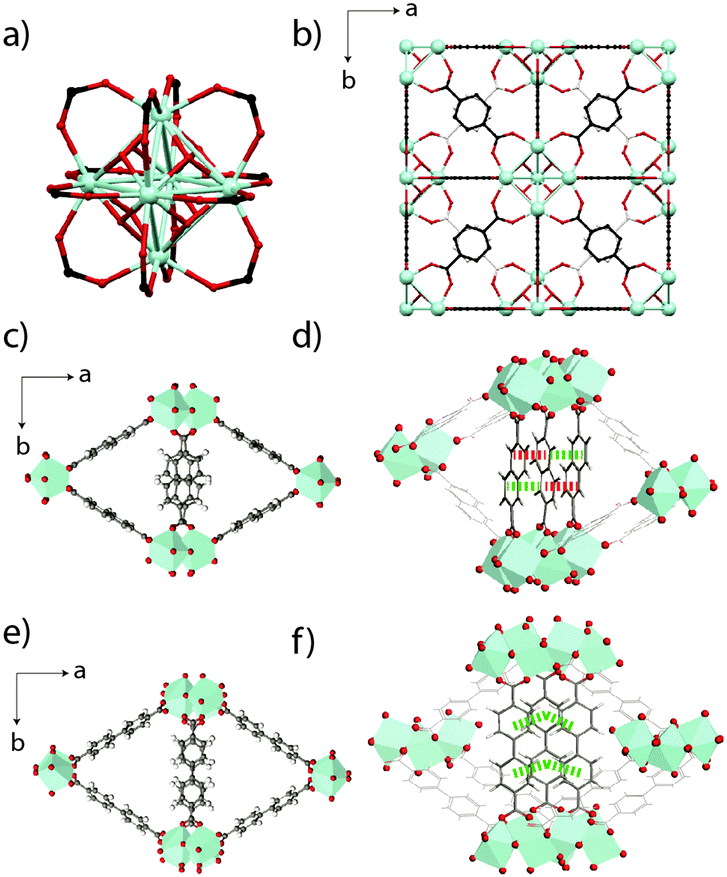 | ||
| Fig. 1 (a) The Zr6O4(OH)4 inorganic node present in UiO-66. (b) Unit cell of UiO-66 viewed along a cubic axis. Carbon atoms behind those shown in the foreground are coloured off-white for clarity. (c) The MIL-140B crystal structure proposed in ref. 23, viewed along the c-axis, along with (d) π-stacking distances along the c-axis between the ndc ligands. Red – 4.46 Å, green – 3.63 Å. (e) The MIL-140C crystal structure proposed in ref. 23, with (f) corresponding π-stacking distances (green – 3.94 Å) along the c-axis between the bpdc linkers. Zr atoms are depicted as light blue polyhedra, O is red, C is gray and H is white. | ||
The two related MOFs, MIL-140B [ZrO(O2C-C10H6-CO2)] and MIL-140C [ZrO(O2C-C12H8-CO2)], also collapse relatively quickly upon ball-milling. Respectively crystallizing in the space groups Cc and C2/c, each contains seven-coordinate Zr4+ ions, which are connected to four 2,6-napthalene dicarboxylate (ndc) and 4,4′-biphenyldicarboxylate (bpdc) ligands respectively. Purely inorganic ZrO chains line the c-axis of the cells and delimit triangular channels (Fig. 1c), which are larger in MIL-140C due to the larger bpdc organic linker used (Fig. 1e). Whilst π-stacking along the c-axis between all bpdc ligands (i.e. those bisecting the lozenge-shaped channels) is observed in MIL-140C, only 50% of the corresponding ndc ligands in MIL-140B participate in this stabilization (Fig. 1d and f).23
Connections between the mechanical properties of MOFs and their defect content are of interest. UiO-66 has previously been demonstrated to be prone to linker vacancies,22,24 the extent of which can be tuned to yield differential adsorption and thermo-mechanical properties.25,26 Specifically, recent work has pointed to the direct coordination of H2O and solvent molecules to Zr4+ nodes in defective UiO-type structures.27,28 Differences between simulated and experimental cell parameters of solvothermally synthesized MIL-140B point towards the presence of defects in this framework, though microwave based syntheses are recorded as producing a defect free material.29,30 Potential links between defects and amorphization mechanisms are therefore of much interest, alongside the structure and properties of the resultant amorphous products.
We use infrared spectroscopy and pair distribution function (PDF) measurements to structurally characterize the products of the ball-milling induced collapse of the rigid UiO-66, MIL-140B and MIL-140C frameworks. Density functional theory (DFT) calculations reveal the presence of defects in MIL-140B. We build defective models, and alongside 13C solid state magic angle spinning (MAS) nuclear magnetic resonance (NMR), use these to suggest the likely nature of the defects in the framework. Overall, we find a quantifiable partial breakage of metal–ligand bonding in each case, though, perhaps surprisingly, the backbone ZrO chains of the MIL-140 frameworks are also damaged in the process. The [Zr6O4(OH)4] clusters of UiO-66 however remain intact.
Experimental
Materials selection and synthesis
Samples were synthesized according to previous procedures.18,23Ball milling
50 mg of each sample was placed in a 10 mL stainless steel jar along with one 9 mm diameter stainless steel ball. The material was then ball-milled for the specified time in a Retsch MM400 grinder mill operating at 20 Hz.Computational details
All geometry optimization calculations are based on density functional theory (DFT) and performed using the Vienna Ab initio Simulation Package (VASP).31 Lattice parameters and atomic positions were optimized until the forces on all atoms were smaller than 0.01 eV Å−1 and the SCF convergence criteria is below 1 × 10⁻⁵ eV. A plane-wave basis set with an energy cutoff of 600 eV was employed, along with the Perdew–Burke–Ernzerhof (PBE) exchange–correlation functional.32 The long-range weak dispersion interactions were taken into account by different schemes: (1) the DFT-D method of Grimme (DFT-D233 and DFT-D334) and (2) one of the non-local van der Waals functionals of Langreth and Lunquist, namely the optB88-vdW functional.35,36 The electron-ion interactions were described by the projector augmented wave (PAW) method37 in the implementation of Kresse and Joubert.38 The Brillouin zone integration was performed using a (1 × 1 × 2) Monkhorst–Pack grid.39The NMR chemical shift calculations were performed at the VASP optimized geometries using the QUANTUM-ESPRESSO software.40 The PBE generalized gradient approximation32 was used and the valence electrons were described by norm conserving pseudopotentials in the Kleinman–Bylander form.41 The wave functions are expanded on a plane wave basis set with a kinetic energy cut-off of 816 eV and the convergence threshold for the SCF energy was set to 1.36 × 10⁻⁹ eV. The integrals over the first Brillouin zone are performed at the Γ point for the charge density and chemical shift tensor calculations.
The shielding tensor is computed using the GIPAW42 approach which permits the reproduction of the results of a fully converged all-electron calculation. The isotropic chemical shift δiso is defined as δiso = −[σ − σref] where σ is the isotropic shielding and σref is the isotropic shielding of the same nucleus in a reference system. In the present case, the comparison between the experimental δiso and calculated δiso13C chemical shift values for carboxylate of benzoic acid43 (δiso = 172.0 ppm)44 allowed to determine σref for this nucleus.
Characterization of materials
Results and discussion
Powder X-ray diffraction and infrared spectroscopy
Consistent with prior work, ball-milling of crystalline samples of UiO-66 (10 min), MIL-140B (15 min) and MIL-140C (20 min) resulted in the disappearance of Bragg peaks from the powder X-ray diffraction patterns (Fig. 2). We term the products amUiO-66 and amMIL-140C, where the subscript m refers to amorphization by mechanochemical means. An asterisk denotes the retention of some Bragg peaks in the diffraction pattern of MIL-140B after milling (amMIL-140B*, Fig. 2b inset). Infrared spectroscopy revealed the emergence of a band centered at ca. 1700 cm−1 upon amorphization of the MIL-140 samples, which is assigned to the uncoordinated carbonyl stretching frequency (Fig. 2). An increase in intensity of this band was also noted upon collapse of UiO-66, where uncoordinated bdc ligands within the pores result in a small feature at 1700 cm−1 in the crystalline sample.46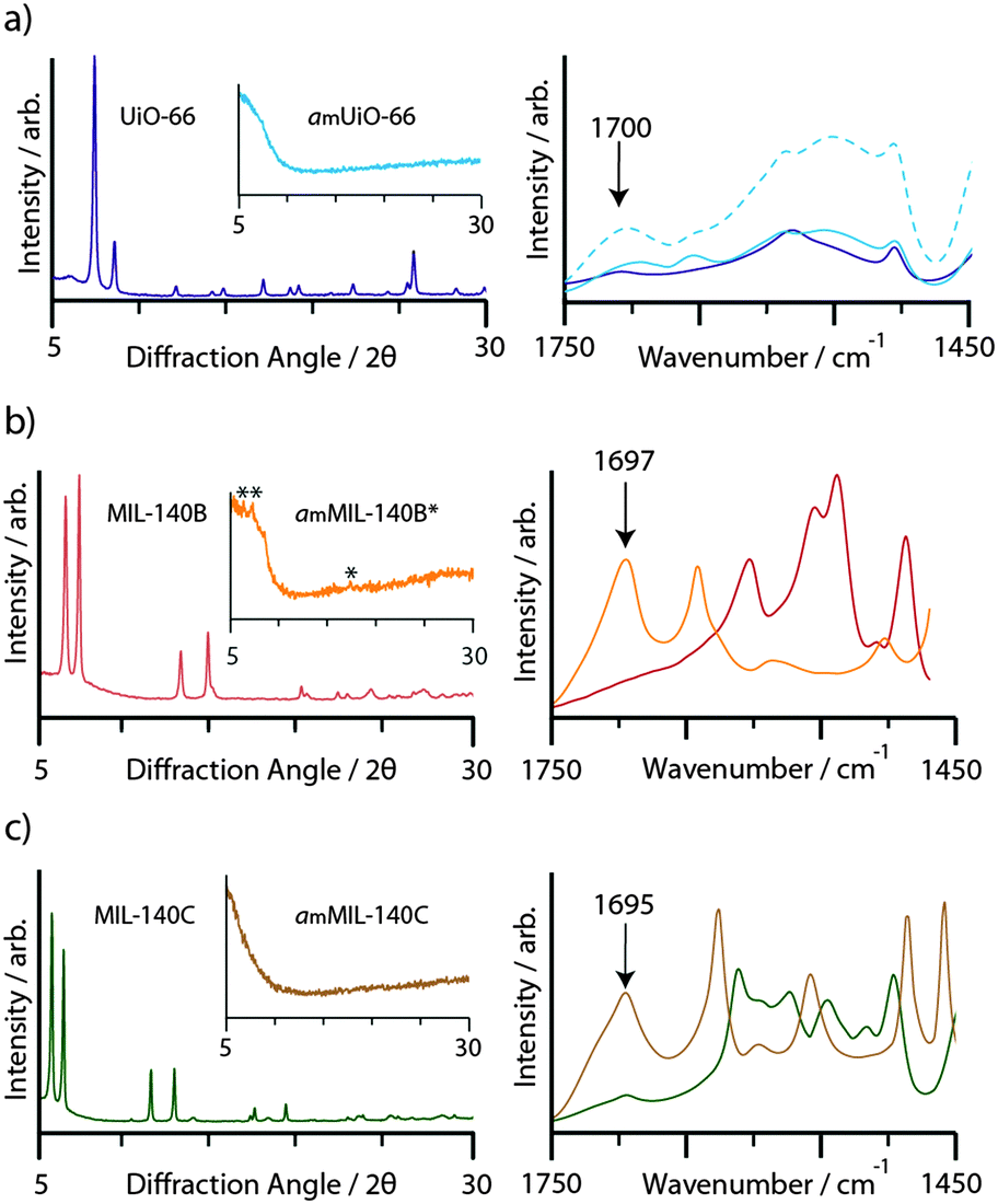 | ||
| Fig. 2 CuKα1 powder X-ray diffraction patterns, and IR spectra, of crystalline and (inset) amorphous samples (left hand plots), complete with IR spectra of the region 1450–1750 cm−1 (right hand plots). (a) UiO-66: dark blue, amUiO-66: light blue, amUiO-66 after 20 minutes ball milling: broken light blue, (b) MIL-140B: red, amMIL-140B*: orange, (c) MIL-140C: green, amMIL-140C: brown. | ||
Nuclear magnetic resonance spectroscopy
NMR has proven a valuable tool in the detailed structural characterization of MOFs.47–52 The qualitative observation of partial destruction of metal–ligand bonding motivated us to perform solid-state 13C MAS NMR on the compounds. The experimental spectrum of UiO-66 (Fig. 3a) contains three peaks. Based on prior work,46 resonances at 128 ppm and 137 ppm are assigned to the two types of carbon on the bdc aromatic ring, whilst the carboxylate-binding group gives rise to the signal at 170 ppm. The 13C NMR spectrum of MIL-140B (Fig. 3b) is significantly more complicated, containing multiple signals in the 120–140 ppm region and two distinct resonances at 173.5 ppm and 175 ppm. A further increase in complexity is noted in the 13C MAS NMR spectrum of MIL-140C (Fig. 3c), which now contains three resonances in the region 170–175 ppm.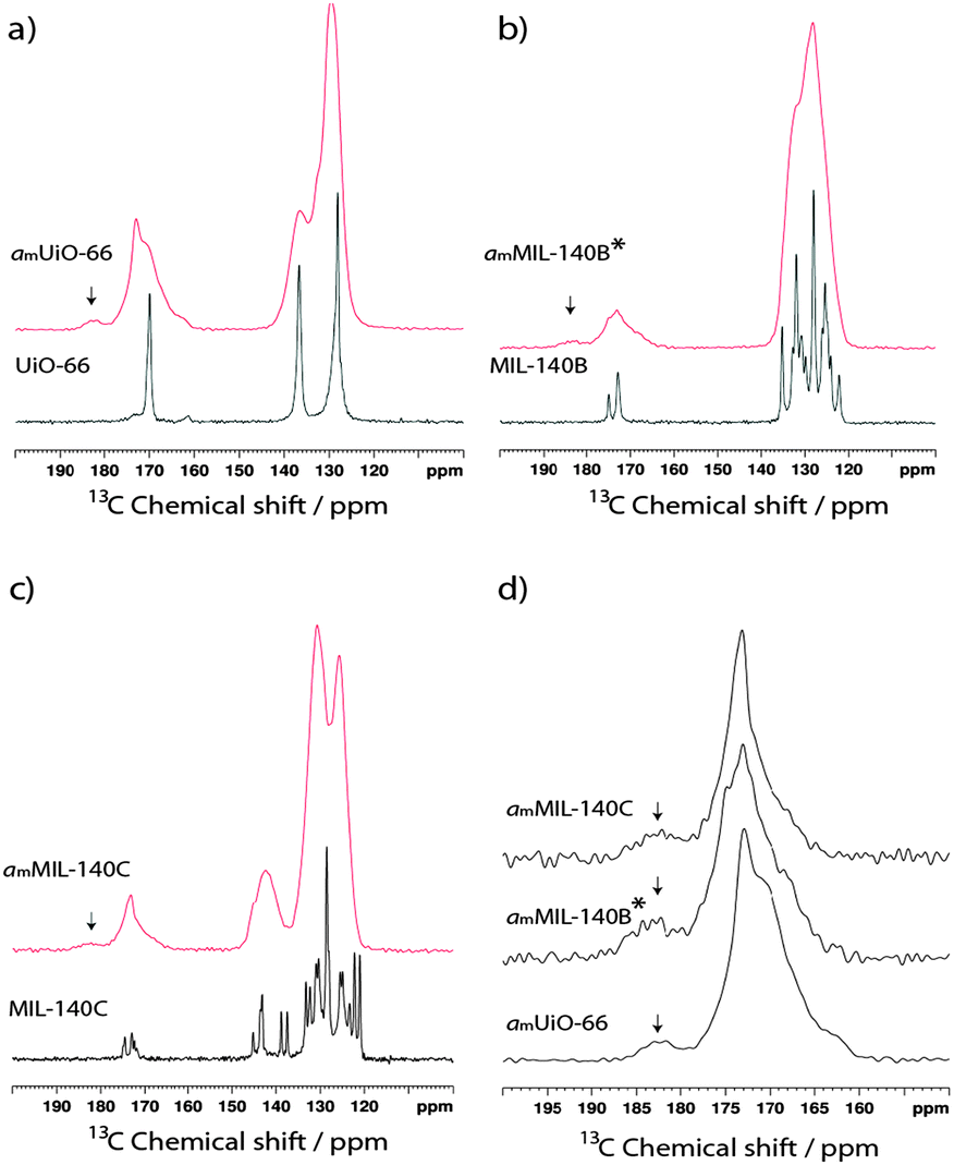 | ||
| Fig. 3 13C MAS NMR spectra of crystalline (black) and amorphous (red) samples of (a) UiO-66, (b) MIL-140B and (c) MIL-140C. (d) Magnified view of the 150–200 ppm region of the amorphous samples. | ||
Upon amorphization, significant peak broadening of all signals is observed in the experimental spectra, though an indication of retention of the bdc ligand in amUiO-66 is given by the two identifiable signals which make up the broad peak at low chemical shift (Fig. 3a). Coalescence of the signals belonging to non-carboxylate carbon atoms in amMIL-140B* is observed (Fig. 3b), while three distinct features in the 120–145 ppm 13C spectrum of amMIL-140C remain apparent (Fig. 3c). Loss of chemically distinct ligand environments in the MIL-140 frameworks was confirmed by coalescence of carboxylate peaks at ca. 170 ppm in each case.
A small additional feature at ca. 182.5 ppm appears upon amorphization for all three samples (Fig. 3d). The higher chemical shift of this peak is consistent with loss of carboxylate coordination to the Zr4+ ions upon structural collapse. Integration traces of the carboxylate signals in the amorphous samples yielded the approximate ratio of this emergent peak to the main peak. In amUiO-66, the new feature was found to account for ca. 6.8% of the total intensity from the carboxylate carbon, suggesting a low degree of Zr–OOC bond breaking. This is raised to ca. 13.2% and 11.0% respectively in MIL-140B and MIL-140C, implying a higher degree of coordinate bond breaking in these samples upon amorphization.
Non-defective modeling of MIL-140B
In order to understand and better assign individual features in the experimental 13C NMR spectra of MIL-140B and MIL-140C, DFT calculations were performed using their previously reported crystal structures,23 which were derived using a computationally assisted strategy from the crystal structure of MIL-140A (the bdc-based isoreticular structure); the only one solved by Rietveld refinement of X-ray powder diffraction data.23 Simulated cell parameters and volumes for MIL-140B and MIL-140C were obtained in the present work upon fully relaxing coordinates and cell parameters, using four different DFT approaches: one with no dispersion correction (PBE), two with dispersion correction using the DFT-D approach of Grimme by means of D2 and D3 corrections (PBE-D233 and PBE-D334), and one employing one of the non-local van der Waals functionals (optB88-vdW).35,36 We first discuss attempts at structural optimization of alternative, non-defective MIL-140B structures, before considering defective MIL-140B models and their relative energetics, and then their respective calculated 13C NMR responses.Upon comparison of DFT results with the experimental values for MIL-140B (Table 1), all employed DFT schemes converge systematically to a larger cell volume than the experimental one (7.5% error). This mainly emanates from the recurrent overestimation of the lattice constant a found at ∼28 schemas (4.8% error), while b and c are predicted with excellent accuracy (within 1.5% error). This cell expansion occurs when dispersion corrections are omitted (PBE entry), and is surprisingly maintained when they are taken into account, a result which is not sensitive to the methodology by which the dispersion is calculated (PBE-D2, -D3 and optB88-vdW entries). A further geometry optimization of MIL-140B, constraining its cell parameters to the experimentally determined values (PBE-D3//exp entry), reveals it is much less stable by 1.57 eV than its relaxed MIL-140B counterpart (PBE-D3 entry), pointing towards an inconsistency between the structural model used and the experimentally determined cell parameters. Expectedly, the simulated 13C spectrum of MIL-140B is in very poor agreement with the experimental one, in both regions of carboxylate and aromatic carbons (Fig. S1a, ESI†), supporting a hypothesis of a different, or defective MIL-140B structure not captured in the initial model of ref. 23.
| a (Å) | b (Å) | c (Å) | α (°) | β (°) | γ (°) | V (Å3) | E (eV) | |
|---|---|---|---|---|---|---|---|---|
| MIL-140B | ||||||||
| Exp. ref. 23 | 26.71 | 13.30 | 7.79 | 90 | 92.56 | 90 | 2763.2 | |
| PBE | 28.05 | 13.49 | 8.02 | 90 | 94.26 | 90 | 3024.7 | |
| PBE-D2 | 28.05 | 13.46 | 7.87 | 90 | 93.40 | 90 | 2964.7 | |
| PBE-D3 | 27.95 | 13.46 | 7.91 | 90 | 93.34 | 90 | 2970.7 | 0 |
| PBE-D3//exp | 26.71 | 13.30 | 7.79 | 90 | 92.56 | 90 | 2763.2 | +1.57 |
| optB88-vdW | 28.00 | 13.44 | 7.89 | 90 | 93.82 | 90 | 2963.3 | 0 |
| MIL-140B(r) | ||||||||
| PBE-D2 | 27.65 | 13.41 | 7.84 | 89.32 | 90.12 | 88.86 | 2906.1 | |
| PBE-D3 | 27.56 | 13.41 | 7.88 | 89.50 | 90.34 | 88.81 | 2909.8 | −0.38 |
| optB88-vdW | 27.28 | 13.38 | 7.85 | 91.06 | 88.66 | 88.16 | 2864.8 | −0.47 |
| MIL-140C | a (Å) | b (Å) | c (Å) | α (°) | β (°) | γ (°) | V (Å3) |
|---|---|---|---|---|---|---|---|
| Exp. ref. 23 | 31.03 | 15.51 | 7.82 | 90 | 93.26 | 90 | 3756.6 |
| PBE | 31.52 | 15.63 | 7.97 | 90 | 87.06 | 90 | 3918.3 |
| PBE-D2 | 31.29 | 15.58 | 7.78 | 90 | 89.67 | 90 | 3794.7 |
| PBE-D3 | 31.25 | 15.59 | 7.82 | 90 | 89.32 | 90 | 3810.9 |
| optB88-vdW | 31.16 | 15.59 | 7.78 | 90 | 89.90 | 90 | 3778.8 |
The situation is markedly different with MIL-140C, with excellent predictions from DFT structure optimizations (Table 1 and Fig. S2, ESI†). While dispersion correction-free DFT calculations slightly overestimate the a cell parameter (1.6% error) and cell volume, V (4.3% error), all dispersion-corrected DFT calculations yield excellent agreement when compared to experiment, particularly the optB88-vdW entry with errors reduced to 0.4% and 0.6% for a and V, respectively. As in all MIL-140B calculations, the c parameter is systematically very well predicted. This reflects the structural rigidity associated with the inorganic subunit of the zirconium oxide chains along that direction. Taking the dispersion effects into account improves the simulation of the MIL-140C crystal structure and highlights the importance of the π-stacking stabilizing interactions along the c-axis, which take place with the involvement of all bpdc ligands at regular center-to-center distances of 3.9 Å (Fig. 1f). The simulated NMR spectra provide significantly better agreement with observed NMR shifts, supporting a consistent initial structural model (Fig. S2, ESI†).
The failure of DFT calculations to predict the correct cell volume and lattice parameters for MIL-140B reveals that its stabilization at the smaller observed cell parameters emanates from additional structural features. This together with NMR discrepancies prompted us to an in-depth investigation of the structure and defects in MIL-140B, as a case study.
Enhanced π-stacking in MIL-140B
A first variant of the reported MIL-140B structure, hereby referred to as MIL-140B(r), where (r) indicates the partial rotation of linkers, was therefore constructed by imposing a 180° rotation around the b-axis to the ndc linkers not participating in the π-stacking (Fig. 4a). The resultant MIL-140B(r) model is hence one in which a full π-stacking of ndc linkers along the c-axis occurs. As a result, the fully relaxed MIL-140B(r) model is 0.38 eV lower in energy than the parent MIL-140B, compared at the same level of theory (Table 1, PBE-D3 entry). This stabilization is assigned mainly to the now enhanced π-stacking along c. In addition, the sole rotation of these ndc linkers induces a large contraction along the a-axis, of 0.4–0.7 Å depending on the level of theory, with an error reduced to 2–3%.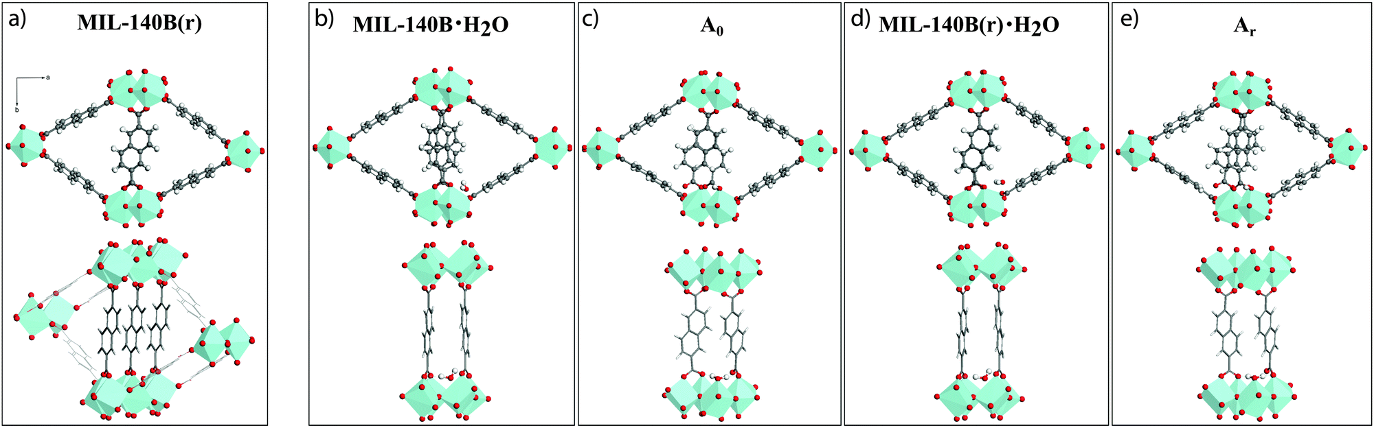 | ||
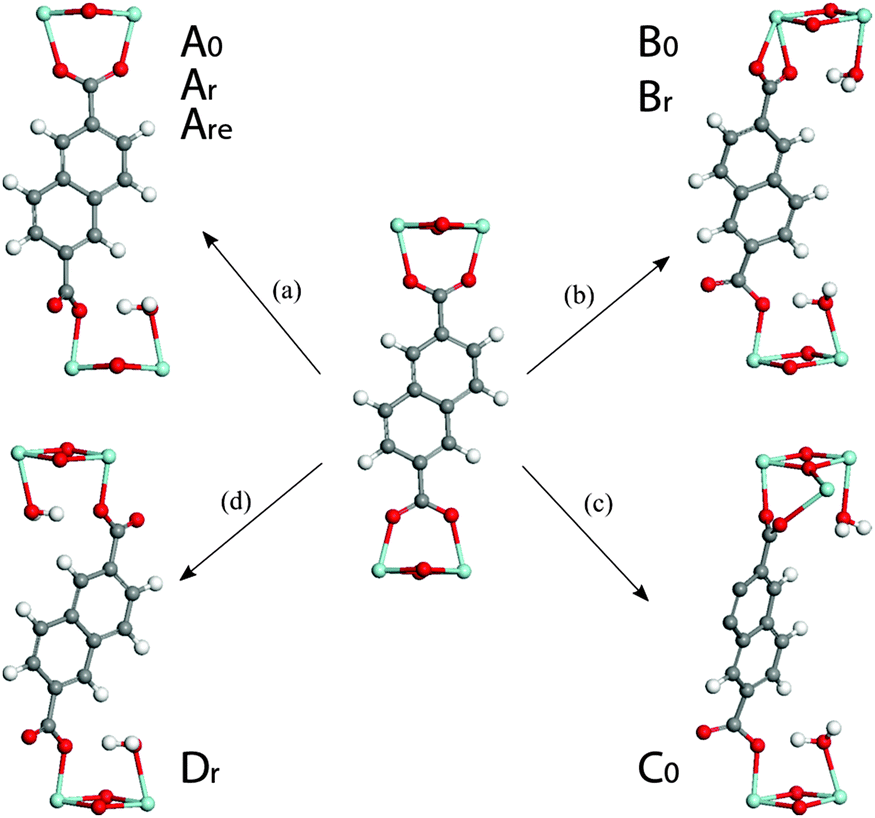
| Fig. 4 Crystal structure of MIL-140B(r), formed by rotating 50% of the ndc linkers which lie along the a-axis, around the b-axis by 180°. Structures of MIL-140B contain one H2O molecule per unit cell viewed along the c-axis. Models called MIL-140B·H2O and MIL-140B(r)·H2O contain an uncoordinated water molecule, while A0 and Ar, are defective models and are built with a H2O molecule coordinates directly to a Zr-center. The latter displaces the linker which becomes monodentate on one its carboxylate end. Zr atoms are depicted as light blue polyhedra, O is red, C is gray and H is white. | ||
Addition of uncoordinated H2O
While being closer to experimental findings, MIL-140B(r) still exhibits overestimated cell parameters. Given recent reports of the defects in UiO-materials being caused by H2O or solvent molecules,27,53 we thus further constructed several non-defective structures, where low concentrations of water are introduced as adsorbed molecules. Table 2 summarizes the optimized cell parameters and their relative energies obtained at the PBE-D3 level of theory.| a (Å) | b (Å) | c (Å) | α (°) | β (°) | γ (°) | V (Å3) | E (eV) | |
|---|---|---|---|---|---|---|---|---|
| Uncoordinated water | ||||||||
| MIL-140B·H2O | 27.84 | 13.47 | 7.89 | 90.57 | 92.79 | 90.02 | 2957.5 | 0 |
| MIL-140B·2H2O | 27.82 | 13.48 | 7.90 | 89.96 | 93.01 | 90.54 | 2955.5 | 0 |
| MIL-140B(r)·H2O | 27.52 | 13.42 | 7.87 | 89.49 | 90.15 | 88.94 | 2905.4 | −0.35 |
| MIL-140B(r)·2H2O | 27.51 | 13.44 | 7.86 | 89.26 | 90.24 | 89.15 | 2905.4 | −0.37 |
| Coordinated water | ||||||||
| Ar | 27.28 | 13.42 | 7.86 | 90.07 | 88.28 | 89.20 | 2875.1 | +0.02 |
| Are | 26.63 | 13.45 | 7.83 | 90.36 | 84.44 | 89.91 | 2789.4 | +0.40 |
| A0 | 27.79 | 13.46 | 7.87 | 90.34 | 92.13 | 90.52 | 2944.2 | +0.21 |
| A0e | 27.56 | 13.49 | 7.85 | 90.79 | 90.12 | 91.10 | 2918.8 | +0.37 |
| Br | 27.40 | 13.41 | 7.85 | 90.67 | 89.54 | 87.65 | 2882.5 | +0.26 |
| B0 | 27.69 | 13.47 | 7.85 | 89.43 | 92.26 | 89.51 | 2925.6 | +0.54 |
| C0 | 27.77 | 13.46 | 7.85 | 90.18 | 93.30 | 89.41 | 2930.2 | +0.82 |
| Dr | 27.10 | 13.45 | 7.86 | 89.45 | 87.19 | 89.77 | 2861.3 | +0.37 |
Two hydrated models were derived from MIL-140B and MIL-140B(r), respectively (labelled “·H2O”), by adding one adsorbed water molecule per cell (Fig. 4b and d). Upon full relaxation, the water molecule preferentially forms hydrogen bonds with two carboxyl oxygen atoms (1.99 and 1.95 Å) of two neighbouring ndc linkers stacked along c, with minor change in cell volumes. The rotated hydrated model was found to be of lower energy (by 0.35 eV) than the non-rotated one, which is ascribed entirely due to the enhanced π-stacking in MIL-140B(r) (see Table 1). Addition of a second uncoordinated water to both models (labelled·2H2O), to a site at the opposite end of the organic linker to the first molecule, did not result in any cell modification nor further stabilization.
Defect modelling
 | ||
| Fig. 5 Formation of different types of defective structures upon direct binding of water on a Zr-center. The names of the defective models derived from each pathway are included for clarity. Zr – light blue, O – red, C – gray, H – white. | ||
In pathway ‘a’, one end of an ndc linker was displaced into a monodentate state, allowing coordination of one H2O molecule to the newly created defect site. Upon relaxation, the chemisorbed water remained bound to Zr and established hydrogen bonds with its two surrounding carboxyl oxygen atoms (1.80 Å). Interestingly, model Ar is isoenergetic to the relative ground state MIL-140B·H2O structure (0.02 eV): the energy penalty for breaking Zr–O(linker) bond and altering the π-stacking is compensated by the coordination of the water molecule to Zr. In addition, unlike the (non-coordinating) adsorption of water, the chemisorption of water on the Zr-center in Ar leads to a significant cell contraction along a (up to ∼0.3 Å) when compared to the water-free model, making Ar a promising defective model candidate.
Extension of this defect with a second coordinated H2O molecule along the a-axis (model Are) induces a relatively low energetic penalty (+0.40 eV). More importantly, this results in a further cell contraction of this defective MIL-140B model along the a lattice constant (a = 26.63 Å), in excellent agreement with the experimentally determined value for the MIL-140B structure of 26.71 Å. Identical treatment of MIL-140B·H2O, the non-rotated system, gave rise to models A0 and A0e, which are only 0.21 eV and 0.37 eV higher in energy than the reference ground state of MIL-140B with uncoordinated water molecule, respectively, with however poor agreement in lattice parameters.
Turning to defect B, we considered translation of the entire ndc linker induced by the chemisorption of two water molecules on the opposite Zr-centers (pathway ‘b’ in Fig. 5). As a result, the linker becomes monodentate on one side and bidentate on the other. The resultant models, Br and B0, are +0.26 and +0.54 eV higher in energy than the reference model.
A third type of defect yielded model C0 (pathway ‘c’, in Fig. 5). Whilst the defect resembles that in pathway ‘b’, the linker binds to two neighbouring Zr-centers along the c direction. This structure was deemed unfavourable by +0.82 eV with respect to the reference defect-free model MIL-140B·2H2O.
A fourth defect structure, modelled by following pathway ‘d’ in Fig. 5, yields Dr. In this structure both ends of an ndc linker were displaced into a monodentate position, allowing coordination of a H2O molecule to each of the two newly created defective Zr sites. It can form with an energy cost of 0.37 eV and shows significant shrinking of the lattice vector a to 27.10 Å.
Overall, this series of calculations tend to suggest that the formation of defects in MIL-140B may occur through the coordination of water molecules to Zr centers together with the displacement of the linker and that such defects are associated with relatively low energy penalties. They also indicate that defect pathways allowing the enhancement of π-stacking of ndc linkers along c direction might be favoured, exemplified in ‘r’ type models.
Whilst possible, defect-incorporating models (Are, Br and Dr), for the reported MIL-140B structure have been suggested, it is equally interesting that some of the features in the predicted NMR shifts agree well with those of amMIL-140B. The range of chemical shifts across the spectra observed shows excellent agreement with those for the amorphized MIL-140B sample. The predicted 13C NMR spectrum of model Br however, is the only one to exhibit a peak in the region 185–190 ppm, which is identified to be a fingerprint of one carboxylate end being bound in a bidentate fashion to Zr4+. Since this is closely reminiscent of the feature which appears upon amorphization, it provides some evidence as to the introduction of defects upon ball-milling of the structure.
Pair distribution function studies
Analysis of the pair distribution function, or the weighted histogram of atom-atom distances,54 of amorphous inorganic zeolites55 and MOFs,12 has in the past yielded useful information on the chemical structure of complex amorphous systems. Room temperature total scattering data were therefore collected on crystalline and amorphous samples using synchrotron radiation (λ = 0.1722 Å, Qmax = 22 Å−1). The resultant structure factors S(Q) (Fig. S4–S6, ESI†) of amUiO-66 and amMIL-140C are devoid of Bragg peaks, confirming the amorphous sample nature. Expectedly, that of amMIL-140B* contains some features due to Bragg scattering. After suitable corrections using the GudrunX software,45 the data were converted to the corresponding PDFs by Fourier transform.56Due to the difficulties in obtaining reliable data below ∼1 Å from X-ray total scattering instruments, the first peak in the PDF of crystalline UiO-66 belonging to a physical atom-atom correlation appears at ∼1.3 Å, which corresponds to C–C or C–O direct linkages (A, Fig. 6a). Other features below 6 Å (B–F) are assigned to various Zr–Zr and Zr–O inter-cluster separations. At longer distances, overlapping contributions from similarly spaced Zr–C atom pairs results in peak broadening and renders precise assignment of the features at ∼6.5 Å and ∼8.6 Å challenging. The large relative scattering cross-section of Zr results in sharp features above 10 Å (G–K) in the PDF of UiO-66, which can be ascribed to Zr atom pairs joined through a bdc linker (Fig. 6b).
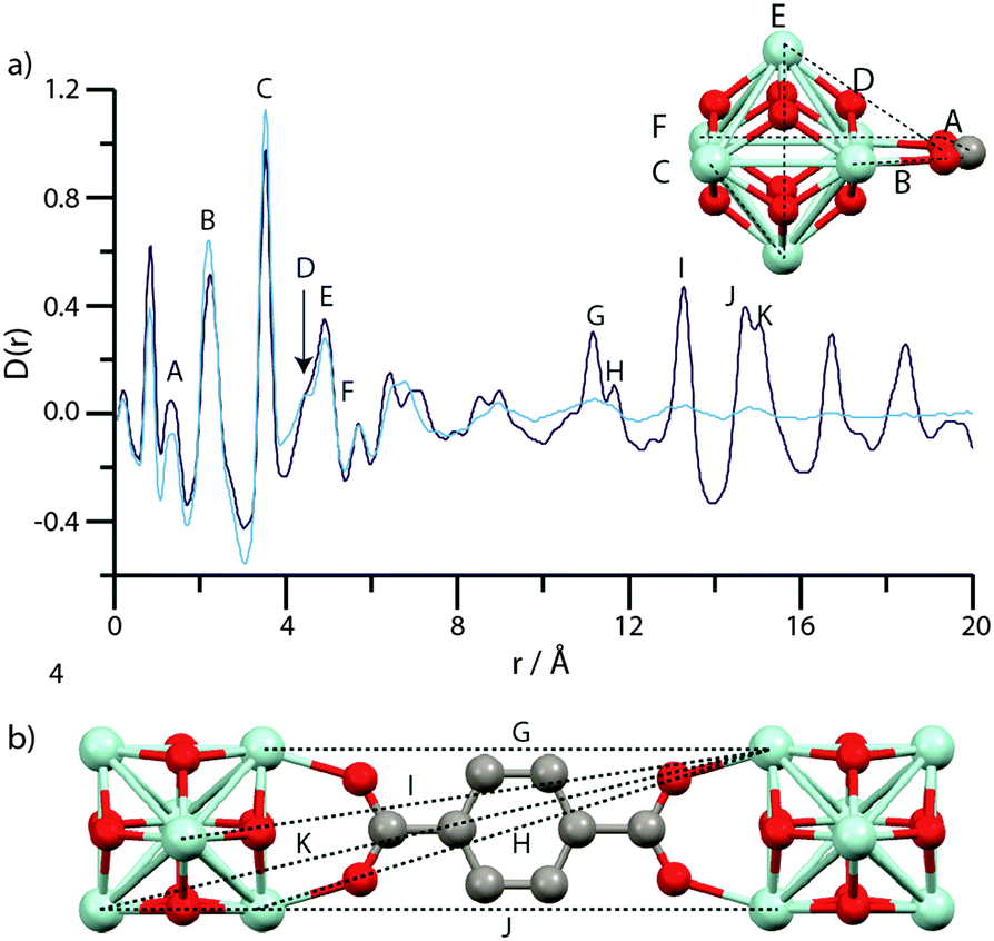 | ||
| Fig. 6 (a) PDF data for UiO-66 (dark blue) and amUiO-66 (light blue). A–F labels of peaks below 8 Å correspond to the indicated correlations in the Zr6O4(OH)4 cluster (inset). (b) Two Zr6O4(OH)4 units linked by a bdc ligand, and some of the significant distances corresponding to the longer r features (G–K) in (a). Zr – light blue, O – red, C – gray, H – omitted. | ||
Below 6 Å, the PDF of amUiO-66 is very similar to UiO-66, with peaks A–F appearing invariant in position between the two and thus confirming the presence of the Zr6O4(OH)4 structural building unit in amUiO-66. Coalescence of the double peaks centered at ∼6.5 Å and ∼8.6 Å occurs upon amorphization, yielding two broad features in the PDF of amUiO-66. The reduction in intensity and severe broadening of these peaks, and those labelled G–K, in amUiO-66 is indicative of the loss of long range-order of the framework. The presence however of some intensity does suggest at least the partial retention of the structural linkage, though substantial changes to Zr–Zr correlations would be expected if only one Zr–O bond were to break. The observable extent of order in amUiO-66 may extend beyond 15.9 Å, though this is the last distance at which correlations can be unambiguously assigned to Zr–Zr atoms separated by the organic linker.
The PDF of MIL-140B (Fig. 7a) contains the expected peaks (L–N) belonging to nearest neighbour C–C/C–O, Zr–O and Zr–Zr distances at ca. 1.3 Å, 2 Å and 3.3 Å, whilst at further distances below 8 Å (O–R), non nearest neighbour correlations of Zr–Zr and Zr–O atoms also elicit sharp features. These corresponding chemical distances relating to L–R are indicated in the inset of Fig. 7a, and all relate to the inorganic ZrO backbone chain. Sharp features associated with crystalline order continue to be observed in the PDF of MIL-140B to distances up to 20 Å, as expected. Key features (S–U) at these longer r values agree well with Zr–Zr distances separated by the 2,6-ndc linker (Fig. 7b).
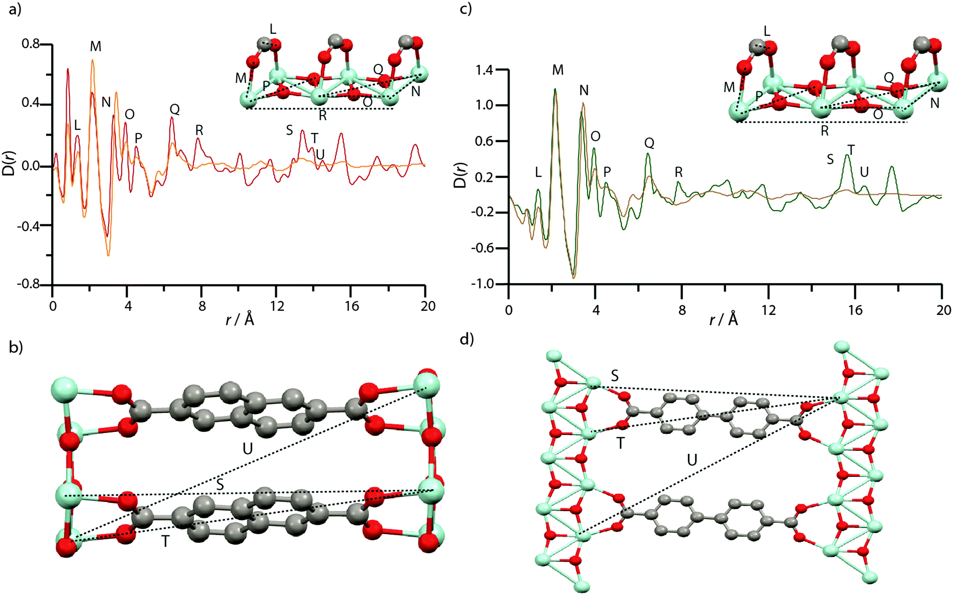 | ||
| Fig. 7 (a) PDF data for MIL-140B and amMIL-140B*. Labels of peaks below 8 Å correspond to the indicated correlations in the ZrO inorganic chains (inset). (b) Two ZrO chains linked by 2,6-ndc, and the distances corresponding to the longer r features in (a). (c) PDF data for MIL-140C and amMIL-140C. Labels of peaks below 8 Å correspond to the indicated correlations in the ZrO inorganic chains, as in MIL-140B (inset). (d) Two ZrO chains linked by bpdc, and the distances corresponding to the longer r features in (a). Zr – light blue, O – red, C – gray, H – omitted. To facilitate assignment of features, partial PDFs were calculated using the PDFgui software (Fig. S7–S9, ESI†).57 All PDFs of crystalline species are, as expected, dominated by correlations involving Zr, due to the larger X-ray scattering cross section of Zr relative to C, O and H. | ||
Features L and M are located in the same position in the PDF of amMIL-140B* (Fig. 7a), though N, which corresponds to the nearest Zr–Zr distance in the inorganic backbone, appears to lengthen from 3.3 Å to 3.5 Å upon amorphization. Another noticeable change in the PDF of amMIL-140B* is the loss in intensity of peaks O–Q, which correspond to non-nearest neighbour Zr and O distances in the ZrO backbone chains. Somewhat surprisingly, the peak at 7.8 Å, labelled R, disappears entirely on going from MIL-140B to amMIL-140B*, suggesting the rigid ZrO inorganic chain no longer remains intact when longer Zr–Zr correlations are considered. Indeed, changes are apparent at even shorter Zr–Zr length scales, with substantial deterioration of the intensity of the Zr–O–Zr (O) peak intensity at 4.5 Å, which suggests that some Zr–O bonds have been broken during the ball-milling process, causing the chain to twist. Given this partial destruction of the continuous ZrO backbone, it is surprising that pair correlations relating to Zr atoms separated by the organic linker (S, T and U) persist in amMIL-140B*, with some degree of correlated order extending to ca. 15.9 Å. Above this distance, the PDF of amMIL-140B* is featureless, in sharp contrast to its crystalline counterpart.
The near-identical nature of the MIL-140C framework, aside from the slightly longer organic linker, led to the labelling of corresponding distances in the PDFs with the same notation as that used in the MIL-140B PDF. Similar differences between amorphous and crystalline frameworks are observed in the PDFs of MIL-140C and amMIL-140C (Fig. 7c and d). In particular, the same lengthening of nearest Zr–Zr distances (N) upon amorphization is witnessed. In addition, very similar reductions in the intensity of the peak belonging to nearest neighbour Zr–O correlations at 4.5 Å (O) are also observed whilst there is very little intensity in further Zr–O correlations (P–R).
This observation provides confidence that the ZrO backbone shared by both MIL-140B and MIL-140C, undergoes significant distortion during ball-milling, though some order persists in the PDF of amMIL-140C, to 17.6 Å (S, T and U). These distances, as in amMIL-140B*, correspond to two Zr atoms separated by the larger bpdc organic linker (Fig. 7d).
Conclusions
The results further contribute to the area of non-crystalline metal–organic frameworks and provide insight into the relationship between defects and amorphization. We have identified possible modes of defect incorporation into the structure of MIL-140B; defects investigated include coordinated water to Zr centers combined with linker displacement. Such defective models provide significantly better agreement with the experimentally observed structural cell parameters than the defect free ones. DFT calculations of the chemical shifts of some models also show similar features to those witnessed experimentally upon amorphization of MIL-140B. We anticipate that the occurrence of such defects might be applicable to other MOFs, given the prevalence of carboxylate linkers in this family.In addition to solid state NMR, we have used pair distribution function analysis to show that the amorphization of the prototypical UiO-66 framework proceeds via partial breakage of Zr–carboxylate bonds, though the rigid Zr6O4(OH)4 inorganic building unit appears to remain intact. This is in stark contrast to MIL-140B and MIL-140C, where in addition to metal–carboxylate bond breaking, the inorganic backbone is also heavily damaged during the ball-milling process. This mechanism bears a large similarity to the changes seen in the ball-milling of zeolites, where M–O (M = Si, Al) bonds are observed to be broken,58 whilst the inorganic distortions are to be expected given that pure zirconia undergoes phase transitions and eventual amorphization when subjected to ball-milling.59
The different behaviour of the two inorganic units is ascribed to the larger interconnected nature of the inorganic clusters in UiO-66, where 24 Zr–O bonds hold the unit together. This is in contrast to the ZrO chains of the MIL-140 frameworks, where in a unit containing the same number of Zr ions, only 16 Zr–O bonds hold the chain together. Whilst structural defects will also play a role in determining mechanical stability, the research here may be combined with increasing metal–ligand bond strengths,20 to yield ‘strong’ MOFs capable of resisting external stresses.
Acknowledgements
The manuscript was written through contributions of all authors. TDB conceived the initial project. TDB acknowledges Trinity Hall (University of Cambridge) and Professor Anthony K. Cheetham for use of lab facilities. D. G. R. acknowledges the UK MRC for financial support. We thank Diamond Light Source for access to beamline I15 (EE9691) that contributed to the results presented here, and Philip A. Chater and Andrew Cairns for assistance with data collection. T. K. T. and C. M. D. thank the French National Research Agency (ANR project: HOPFAME ANR-13-BS07-0002-01) and the Foundation de l'Orangerie for funding. The calculations have been performed using the HPC resources from GENCI (CINES/TGCC/IDRIS) through Grant (2015-097343 and -091461). B. B., B. V. d. V. and D. D. V. gratefully acknowledge the FWO for funding (aspirant grant).Notes and references
- H. Furukawa, K. E. Cordova, M. O'Keeffe and O. M. Yaghi, Science, 2013, 341, 974–986 CrossRef CAS PubMed.
- J. E. Mondloch, M. J. Katz, W. C. Isley III, P. Ghosh, P. Liao, W. Bury, G. W. Wagner, M. C. Hall, J. B. DeCoste, G. W. Peterson, R. Q. Snurr, C. J. Cramer, J. T. Hupp and O. K. Farha, Nat. Mater., 2015, 14, 512–516 CrossRef CAS PubMed.
- T. D. Bennett and A. K. Cheetham, Acc. Chem. Res., 2014, 47, 1555–1562 CrossRef CAS PubMed.
- S. R. Batten, N. R. Champness, X. M. Chen, J. Garcia-Martinez, S. Kitagawa, L. Ohrstrom, M. O'Keeffe, M. P. Suh and J. Reedijk, CrystEngComm, 2012, 14, 3001–3004 RSC.
- T. D. Bennett, J. C. Tan, Y. Z. Yue, E. Baxter, C. D. Ducati, N. Terril, H. Y. Yeung, Z. Zhou, W. Chen, S. Henke, A. K. Cheetham and G. N. Greaves, Nat. Commun., 2015, 6, 10, DOI:10.1038/NCOMMS9079.
- K. W. Chapman, D. F. Sava, G. J. Halder, P. J. Chupas and T. M. Nenoff, J. Am. Chem. Soc., 2011, 133, 18583–18585 CrossRef CAS PubMed.
- F. X. Coudert, Chem. Mater., 2015, 27, 1905–1916 CrossRef CAS.
- D. Umeyama, S. Horike, M. Inukai, T. Itakura and S. Kitagawa, J. Am. Chem. Soc., 2015, 137, 864–870 CrossRef CAS PubMed.
- G. Givaja, P. Amo-Ochoa, C. J. Gomez-Garcia and F. Zamora, Chem. Soc. Rev., 2012, 41, 115–147 RSC.
- J. Haines, C. Levelut, A. Isambert, P. Hebert, S. Kohara, D. A. Keen, T. Hammouda and D. Andrault, J. Am. Chem. Soc., 2009, 131, 12333–12338 CrossRef CAS PubMed.
- S. Jiang, K. E. Jelfs, D. Holden, T. Hasell, S. Y. Chong, M. Haranczyk, A. Trewin and A. I. Cooper, J. Am. Chem. Soc., 2013, 135, 17818–17830 CrossRef CAS PubMed.
- T. D. Bennett, A. L. Goodwin, M. T. Dove, D. A. Keen, M. G. Tucker, E. R. Barney, A. K. Soper, E. G. Bithell, J. C. Tan and A. K. Cheetham, Phys. Rev. Lett., 2010, 104, 115503 CrossRef PubMed.
- S. L. James and T. Friscic, Chem. Soc. Rev., 2013, 42, 7494–7496 RSC.
- A. D. Katsenis, A. Puskaric, V. Strukil, C. Mottillo, P. A. Julien, K. Uzarevic, M. H. Pham, T. O. Do, S. A. J. Kimber, P. Lazic, O. Magdysyuk, R. E. Dinnebier, I. Halasz and T. Friscic, Nat. Commun., 2015, 6, 10, DOI:10.1038/ncomms7662.
- T. D. Bennett, J. Sotelo, J. C. Tan and S. A. Moggach, CrystEngComm, 2015, 17, 286–289 RSC.
- A. U. Ortiz, A. Boutin, A. H. Fuchs and F. X. Coudert, J. Phys. Chem. Lett., 2013, 4, 1861–1865 CrossRef CAS PubMed.
- J. C. Tan, B. Civalleri, C. C. Lin, L. Valenzano, R. Galvelis, P. F. Chen, T. D. Bennett, C. Mellot-Draznieks, C. M. Zicovich-Wilson and A. K. Cheetham, Phys. Rev. Lett., 2012, 108, 095502 CrossRef PubMed.
- B. Van de Voorde, I. Stassen, B. Bueken, F. Vermoortele, D. De Vos, R. Ameloot, J. C. Tan and T. D. Bennett, J. Mater. Chem. A, 2015, 3, 1737–1742 CAS.
- H. Wu, T. Yildirim and W. Zhou, J. Phys. Chem. Lett., 2013, 4, 925–930 CrossRef CAS PubMed.
- J. H. Cavka, S. Jakobsen, U. Olsbye, N. Guillou, C. Lamberti, S. Bordiga and K. P. Lillerud, J. Am. Chem. Soc., 2008, 130, 13850–13851 CrossRef PubMed.
- L. Valenzano, B. Civalleri, S. Chavan, S. Bordiga, M. H. Nilsen, S. Jakobsen, K. P. Lillerud and C. Lamberti, Chem. Mater., 2011, 23, 1700–1718 CrossRef CAS.
- H. Wu, Y. S. Chua, V. Krungleviciute, M. Tyagi, P. Chen, T. Yildirim and W. Zhou, J. Am. Chem. Soc., 2013, 135, 10525–10532 CrossRef CAS PubMed.
- V. Guillerm, F. Ragon, M. Dan-Hardi, T. Devic, M. Vishnuvarthan, B. Campo, A. Vimont, G. Clet, Q. Yang, G. Maurin, G. Férey, A. Vittadini, S. Gross and C. Serre, Angew. Chem., Int. Ed., 2012, 51, 9267–9271 CrossRef CAS PubMed.
- Z. L. Fang, B. Bueken, D. E. De Vos and R. A. Fischer, Angew. Chem., Int. Ed., 2015, 54, 7234–7254 CrossRef CAS PubMed.
- G. C. Shearer, S. Chavan, J. Ethiraj, J. G. Vitillo, S. Svelle, U. Olsbye, C. Lamberti, S. Bordiga and K. P. Lillerud, Chem. Mater., 2014, 26, 4068–4071 CrossRef CAS.
- M. J. Cliffe, W. Wan, X. D. Zou, P. A. Chater, A. K. Kleppe, M. G. Tucker, H. Wilhelm, N. P. Funnell, F. X. Coudert and A. L. Goodwin, Nat. Commun., 2014, 5, 4176 CAS.
- C. A. Trickett, K. J. Gagnon, S. Lee, F. Gandara, H. B. Bürgi and O. Yaghi, Angew. Chem., Int. Ed., 2015, 54, 1–7 CrossRef PubMed.
- P. Ghosh, Y. J. Colon and R. Q. Snurr, Chem. Commun., 2014, 50, 11329–11331 RSC.
- W. B. Liang, R. Babarao, T. L. Church and D. M. D'Alessandro, Chem. Commun., 2015, 51, 11286–11289 RSC.
- W. B. Liang and D. M. D'alessandro, Chem. Commun., 2013, 49, 3706–3708 RSC.
- G. Kresse and J. Furthmuller, Comput. Mater. Sci., 1996, 6, 15–50 CrossRef CAS.
- J. P. Perdew, K. Burke and M. Ernzerhof, Phys. Rev. Lett., 1996, 77, 3865–3868 CrossRef CAS PubMed.
- S. Grimme, J. Comput. Chem., 2006, 27, 1787–1799 CrossRef CAS PubMed.
- S. Grimme, J. Antony, S. Ehrlich and H. Krieg, J. Chem. Phys., 2010, 132, 154104 CrossRef PubMed.
- J. Klimes, D. R. Bowler and A. Michaelides, Phys. Rev. B: Condens. Matter Mater. Phys., 2011, 83, 195131 CrossRef.
- D. C. Langreth, B. I. Lundqvist, S. D. Chakarova-Kack, V. R. Cooper, M. Dion, P. Hyldgaard, A. Kelkkanen, J. Kleis, L. Z. Kong, S. Li, P. G. Moses, E. Murray, A. Puzder, H. Rydberg, E. Schroder and T. Thonhauser, J. Phys.: Condens. Matter, 2009, 21, 084203 CrossRef CAS PubMed.
- P. E. Blochl, Phys. Rev. B: Condens. Matter Mater. Phys., 1994, 50, 17953–17979 CrossRef.
- G. Kresse and D. Joubert, Phys. Rev. B: Condens. Matter Mater. Phys., 1999, 59, 1758–1775 CrossRef CAS.
- H. J. Monkhorst and J. D. Pack, Phys. Rev. B: Condens. Matter Mater. Phys., 1976, 13, 5188–5192 CrossRef.
- P. Giannozzi, S. Baroni, N. Bonini, M. Calandra, R. Car, C. Cavazzoni, D. Ceresoli, G. L. Chiarotti, M. Cococcioni, I. Dabo, A. Dal Corso, S. de Gironcoli, S. Fabris, G. Fratesi, R. Gebauer, U. Gerstmann, C. Gougoussis, A. Kokalj, M. Lazzeri, L. Martin-Samos, N. Marzari, F. Mauri, R. Mazzarello, S. Paolini, A. Pasquarello, L. Paulatto, C. Sbraccia, S. Scandolo, G. Sclauzero, A. P. Seitsonen, A. Smogunov, P. Umari and R. M. Wentzcovitch, J. Phys.: Condens. Matter, 2009, 21, 395502 CrossRef PubMed.
- L. Kleinman and D. M. Bylander, Phys. Rev. Lett., 1982, 48, 1425–1428 CrossRef CAS.
- C. J. Pickard and F. Mauri, Phys. Rev. B: Condens. Matter Mater. Phys., 2001, 63, 245101 CrossRef.
- G. Bruno and L. Randaccio, Acta Crystallogr., Sect. B: Struct. Crystallogr. Cryst. Chem., 1980, 36, 1711–1712 CrossRef.
- F. Babonneau, L. Yeung, N. Steunou, C. Gervais, A. Ramila and M. Vallet-Regi, J. Sol-Gel Sci. Technol., 2004, 31, 219–223 CrossRef CAS.
- A. K. Soper, Tech. Rep. RAL-TR-2011-013, 2011.
- S. Devautour-Vinot, G. Maurin, C. Serre, P. Horcajada, D. P. da Cunha, V. Guillerm, E. D. Costa, F. Taulelle and C. Martineau, Chem. Mater., 2012, 24, 2168–2177 CrossRef CAS.
- S. B. Kalidindi, S. Nayak, M. E. Briggs, S. Jansat, A. P. Katsoulidis, G. J. Miller, J. E. Warren, D. Antypov, F. Cora, B. Slater, M. R. Prestly, C. Marti-Gastaldo and M. J. Rosseinsky, Angew. Chem., Int. Ed., 2015, 54, 221–226 CrossRef CAS PubMed.
- P. He, B. E. G. Lucier, V. V. Terskikh, Q. Shi, J. X. Dong, Y. Y. Chu, A. M. Zheng, A. Sutrisno and Y. N. Huang, J. Phys. Chem. C, 2014, 118, 23728–23744 CAS.
- G. Mali, J. Trebosc, C. Martineau and M. Mazaj, J. Phys. Chem. C, 2015, 119, 7831–7841 CAS.
- P. He, J. Xu, V. V. Terskikh, A. Sutrisno, H. Y. Nie and Y. N. Huang, J. Phys. Chem. C, 2013, 117, 16953–16960 CAS.
- H. C. Hoffmann, M. Debowski, P. Muller, S. Paasch, I. Senkovska, S. Kaskel and E. Brunner, Materials, 2012, 5, 2537–2572 CrossRef CAS.
- M. Baias, A. Lesage, S. Aguado, J. Canivet, V. Moizan-Basle, N. Audebrand, D. Farrusseng and L. Emsley, Angew. Chem., Int. Ed., 2015, 54, 5971–5976 CrossRef CAS PubMed.
- S. Oien, D. Wragg, H. Reinsch, S. Svelle, S. Bordiga, C. Lamberti and K. P. Lillerud, Cryst. Growth Des., 2014, 14, 5370–5372 Search PubMed.
- P. K. Allan, K. W. Chapman, P. J. Chupas, J. A. Hriljac, C. L. Renouf, T. C. A. Lucas and R. E. Morris, Chem. Sci., 2012, 3, 2559–2564 RSC.
- J. E. Readman, P. M. Forster, K. W. Chapman, P. J. Chupas, J. B. Parise and J. A. Hriljac, Chem. Commun., 2009, 3383–3385 RSC.
- D. A. Keen, J. Appl. Crystallogr., 2001, 34, 172–177 CrossRef CAS.
- C. L. Farrow, P. Juhas, J. W. Liu, D. Bryndin, E. S. Bozin, J. Bloch, T. Proffen and S. J. L. Billinge, J. Phys.: Condens. Matter, 2007, 19, 335219 CrossRef CAS PubMed.
- C. Kosanovic, J. Bronic, B. Subotic, I. Smit, M. Stubicar, A. Tonejc and T. Yamamoto, Zeolites, 1993, 13, 261–268 CrossRef CAS.
- T. Puclin and W. A. Kaczmarek, Colloids Surf., A, 1997, 129, 365–375 CrossRef.
Footnote |
| † Electronic supplementary information (ESI) available: 13C NMR, DFT, PDF analysis. See DOI: 10.1039/c5cp06798g |
| This journal is © the Owner Societies 2016 |