 Open Access Article
Creative Commons Attribution 3.0 Unported Licence
Phosphorescence quenching of fac-tris(2-phenylpyridyl)iridium(III) complexes in thin films on dielectric surfaces
J. C.
Ribierre
a,
A.
Ruseckas
a,
S. V.
Staton
b,
K.
Knights
b,
N.
Cumpstey
b,
P. L.
Burn
*bc and
I. D. W.
Samuel
*a
aOrganic Semiconductor Centre, SUPA, School of Physics and Astronomy, University of St Andrews, North Haugh, St Andrews, Fife KY16 9SS, UK. E-mail: idws@st-andrews.ac.uk
bDepartment of Chemistry, University of Oxford, Chemistry Research Laboratory, Mansfield Road, OX1 3TA Oxford, UK
cCentre for Organic Photonics and Electronics, School of Chemistry and Molecular Biosciences, University of Queensland, Queensland 4072, Australia. E-mail: p.burn2@uq.edu.au
First published on 21st December 2015
Abstract
We study the influence of the film thickness on the time-resolved phosphorescence and the luminescence quantum yield of fac-tris(2-phenylpyridyl)iridium(III) [Ir(ppy)3]-cored dendrimers deposited on dielectric substrates. A correlation is observed between the surface quenching velocity and the quenching rate by intermolecular interactions in the bulk film, which suggests that both processes are controlled by dipole–dipole interactions between Ir(ppy)3 complexes at the core of the dendrimers. It is also found that the surface quenching velocity decreases as the refractive index of the substrate is increased. This can be explained by partial screening of dipole–dipole interactions by the dielectric environment.
1. Introduction
Iridium(III) complexes have attracted intensive attention as phosphorescent emitters for organic light-emitting diodes (OLEDs) because they can have internal quantum efficiencies of 100%.1–5 Their short triplet excited state lifetime (∼μs) enables high brightness devices and their good color tunability make them particularly attractive for displays. Recently, electrophosphorescent devices based on an exciplex-forming co-host doped with an iridium(III) complex emitter have been reported with external quantum efficiencies exceeding 35%.6 Despite the recent progress in the development of high performance phosphorescent and thermally-assisted delayed fluorescence (TADF) OLEDs,6–8 their efficiency is often reduced due to triplet quenching by intermolecular interactions, exciton–exciton annihilation and exciton–polaron interactions,9–12 which can be minimised by device and materials engineering. For instance, triplet–triplet annihilation and concentration quenching losses can be reduced in phosphorescent organic thin films using iridium(III) complexes within a dendritic structure. Surface quenching of phosphorescence has also been observed in very thin films deposited on fused silica substrates, but the mechanism by which this occurs has still not been elucidated.12,13 The recent advances in organic electroluminescent materials and devices make it essential to fully understand all these quenching mechanisms.In this paper, we explore surface quenching of phosphorescence in films of several fac-tris(2-phenylpyridyl)iridium(III) [Ir(ppy)3]-cored dendrimers with different spacing between them, with the spacing controlled by the structure of the dendrimer as well as by blending with a large optical gap host.14–19 The molecular structures of the first generation [Ir(ppy)3]-cored dendrimers used in this work are shown in Fig. 1. We report a study on the thickness dependence of the decay of the dendrimer thin film phosphorescence and describe the results using a model based on surface quenching of triplets at the top and bottom interfaces of the film. The roles of exciton diffusion, the bulk photophysical properties of the dendrimer films and the refractive index of the substrates on the surface quenching effects are discussed, providing important insights into the triplet quenching mechanisms in phosphorescent organic thin films. Our results not only broaden our understanding of triplet-state photophysics, but are also of practical interest for the development of light-emitting devices, in particular electrophosphorescent organic field-effect transistors.20
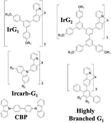 | ||
| Fig. 1 Chemical structures of the macromolecules used in this work. R1 = 2-ethylhexyl, R2 = (9,9-di-n-propylfluoren-2-yl) and R3 = 4-(9,9-di-n-propylfluoren-2-yl)phenyl. | ||
2. Experimental section
Dendrimer films were prepared in the ambient atmosphere of a cleanroom by spin-coating a chloroform solution onto pre-cleaned substrates. The substrates were composed of fused silica, borosilicate glass, N-SK10 and SF15 glasses, sapphire, indium tin oxide (ITO) or a poly-(ethylenedioxythiophene):poly(styrenesulfonicacid) (PEDOT:PSS) (Baytron P, Bayer AG, Germany) layer deposited by spin-coating onto a fused silica substrate. The PEDOT:PSS film was then baked at 110 °C for 10 minutes before deposition of the dendrimer films. In addition, a 200 nm poly(N-vinylcarbazole) (PVK) (Sigma-Aldrich, Mw = 1![[thin space (1/6-em)]](https://www.rsc.org/images/entities/char_2009.gif) 100
100![[thin space (1/6-em)]](https://www.rsc.org/images/entities/char_2009.gif) 000) layer was spin-coated onto a fused silica substrate from a chlorobenzene solution and then dendrimer films were deposited from toluene. It has been previously shown that toluene does not dissolve PVK and enables the fabrication of a clean and sharp heterojunction interface, and we assume this is the case in this work.21 The concentration of the dendrimer and 4,4′-bis(N-carbazolyl)-1,1′-biphenyl (CBP) blend solutions varied typically from 1 mg ml−1 to 25 mg ml−1 in order to obtain film thicknesses ranging from 5 to 200 nm. Film thicknesses were measured by variable angle spectroscopic ellipsometry (J.A. Woolam Co., Inc. M-2000DI system) and from the absorbance measured using a Cary Varian model 300 absorption spectrophotometer. The refractive indices of the substrates and the dendrimer films were also determined from ellipsometry. The photoluminescence quantum yield (PLQY) of each film was determined using an integrating sphere purged with flowing nitrogen.22 The samples were excited by a helium-cadmium laser with a wavelength of 325 nm or by a gallium nitride laser diode emitting at 407 nm to avoid absorption by some of the substrates. Time-resolved PL measurements were carried out using the time-correlated single-photon counting technique. The samples were excited at 390 nm by a pulsed laser diode (Picoquant, model PLS 370) giving 10 pJ per pulse at a repetition rate of 20 kHz and were kept in a vacuum of <8 × 10⁻⁴ mbar.
000) layer was spin-coated onto a fused silica substrate from a chlorobenzene solution and then dendrimer films were deposited from toluene. It has been previously shown that toluene does not dissolve PVK and enables the fabrication of a clean and sharp heterojunction interface, and we assume this is the case in this work.21 The concentration of the dendrimer and 4,4′-bis(N-carbazolyl)-1,1′-biphenyl (CBP) blend solutions varied typically from 1 mg ml−1 to 25 mg ml−1 in order to obtain film thicknesses ranging from 5 to 200 nm. Film thicknesses were measured by variable angle spectroscopic ellipsometry (J.A. Woolam Co., Inc. M-2000DI system) and from the absorbance measured using a Cary Varian model 300 absorption spectrophotometer. The refractive indices of the substrates and the dendrimer films were also determined from ellipsometry. The photoluminescence quantum yield (PLQY) of each film was determined using an integrating sphere purged with flowing nitrogen.22 The samples were excited by a helium-cadmium laser with a wavelength of 325 nm or by a gallium nitride laser diode emitting at 407 nm to avoid absorption by some of the substrates. Time-resolved PL measurements were carried out using the time-correlated single-photon counting technique. The samples were excited at 390 nm by a pulsed laser diode (Picoquant, model PLS 370) giving 10 pJ per pulse at a repetition rate of 20 kHz and were kept in a vacuum of <8 × 10⁻⁴ mbar.
3. Results
3.1 Thickness dependence of the phosphorescence
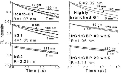
Fig. 2 shows the phosphorescence decays measured for neat dendrimer films of different thicknesses. Note that these decays were measured at low excitation densities (lower than 1017 cm−3) in order to avoid quenching of the emission by triplet–triplet exciton annihilation.12 It can be seen that the decays become faster in thin films. Strong thickness dependence of the decay time is observed in IrG1, Ircarb-G1 and the highly branched G1-dendrimer. The 80 wt% IrG1![[thin space (1/6-em)]](https://www.rsc.org/images/entities/char_2009.gif) :
:![[thin space (1/6-em)]](https://www.rsc.org/images/entities/char_2009.gif) CBP blend showed a weaker dependence, whereas the decay times for films of IrG2 and the 20 wt% IrG1
CBP blend showed a weaker dependence, whereas the decay times for films of IrG2 and the 20 wt% IrG1![[thin space (1/6-em)]](https://www.rsc.org/images/entities/char_2009.gif) :
:![[thin space (1/6-em)]](https://www.rsc.org/images/entities/char_2009.gif) CBP blend was independent of thickness. Note that for these two latter materials, the identical decays in Fig. 2 had to be offset vertically to distinguish between them. A potential explanation for the thickness dependence of the decay time for the neat G1-dendrimer films could be that the photonic mode density at the dielectric interface could affect the radiative emission process.23–26 However, we can rule this out because if it was the changes in radiative lifetime due to microcavity effects would be similar for all materials and the dependence of the phosphorescence decays would not vary between materials.
CBP blend was independent of thickness. Note that for these two latter materials, the identical decays in Fig. 2 had to be offset vertically to distinguish between them. A potential explanation for the thickness dependence of the decay time for the neat G1-dendrimer films could be that the photonic mode density at the dielectric interface could affect the radiative emission process.23–26 However, we can rule this out because if it was the changes in radiative lifetime due to microcavity effects would be similar for all materials and the dependence of the phosphorescence decays would not vary between materials.
In order to study the dependence of the radiative kR and the non-radiative kNR deactivation rates on film thickness using standard equations: PLQY = kR/(kR + kNR) and 1/τ = kR + kNR, we have measured the PLQY of the neat IrG1 films deposited on fused silica substrates. This dendrimer was chosen for these measurements because its basic photophysical properties have been intensively studied in the past and are well documented.12,14,15,19 An excitation wavelength of 325 nm was used in this case to get sufficient absorbance. The PLQY of the 180 nm thick film was found to be 68 ± 7%, dropping to 54 ± 5% and 29 ± 3% for film thicknesses of 140 and 60 nm respectively. Due to the slightly non-single exponential character of some of the PL decays, we assumed single light-emitting species and we used the time interval during which the PL intensity decayed to 1/e of the initial intensity to estimate the PL lifetime τ. The results give a slight decrease of kR values from 7.5 ± 0.7 × 10⁵ s−1 for the 180 nm thick film to 5 ± 0.4 × 10⁵ s−1 for the 60 nm thick film and a three-fold increase of kNR from 4 ± 0.4 × 10⁵ s−1 for the 180 nm film to 12 ± 1 × 10⁵ s−1 for the 60 nm film. This indicates that the decrease of the phosphorescence decay time in thin films is mainly due to an increase in the non-radiative decay rate. The thickness dependence of the PLQY has important ramifications for analysis of the different parameters involved in the expression of OLED external quantum efficiencies such as the light out-coupling efficiency or the singlet–triplet factor.
3.2 Surface quenching of the phosphorescence
The faster decay observed for the thinner films could be explained by quenching at one of the film surfaces, either the film/substrate or the film/vacuum interface. The dynamics of the exciton density N(x,t) at the distance x from the quenching surface can be described using the diffusion equation: | (1) |
 , which is proportional to the measured time-resolved phosphorescence intensity can be described, assuming that the film is optically thin so that the initial excitations are uniform in the film, by a simple rate equation:
 | (2) |
 . Introducing a new function
  and solving eqn (2) we get:
| g(t) = exp(−vt/d). | (3) |
![[thin space (1/6-em)]](https://www.rsc.org/images/entities/char_2009.gif) :
:![[thin space (1/6-em)]](https://www.rsc.org/images/entities/char_2009.gif) CBP (20
CBP (20![[thin space (1/6-em)]](https://www.rsc.org/images/entities/char_2009.gif) :
:![[thin space (1/6-em)]](https://www.rsc.org/images/entities/char_2009.gif) 80 wt%) films no surface quenching was observed, and thus v = 0.
80 wt%) films no surface quenching was observed, and thus v = 0.
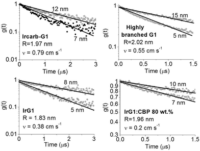 | ||
| Fig. 3 Ratio of the phosphorescence intensity g(t) measured for thin films of given thicknesses on fused silica substrates to that of the limiting case of a thick film. Solid lines are fits to an exponential decay and the values of the surface quenching velocities v obtained using eqn (3) are given for each material as insets. R is the average intermolecular spacing between the iridium(III) complex cores. | ||
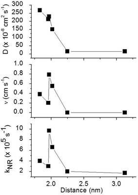
To obtain a better understanding of the surface quenching we have investigated how it correlates with the triplet exciton diffusion and the non-radiative decay rate in the bulk of the materials. From the triplet–triplet exciton annihilation data reported elsewhere,12 we calculated the exciton diffusion constant D using γ = 4πDRa, where γ is the annihilation constant, Ra is the annihilation radius at which annihilation is faster than hopping and is taken to be the spacing distance R between two neighbouring iridium(III) complex cores. The intermolecular spacing R was calculated by assuming the dendrimers are hard spheres and the films have a density of 1.1 g cm−3.27Fig. 4 shows the D values decreasing with an increase of R, which confirms that exciton diffusion can be controlled by the attachment of different types and generations of dendrons, or by blending the dendrimers in a host at various concentrations.12,28,29 The surface quenching velocity v also decreases with an increase in R for R > 1.97 nm. However, two materials with the shortest intermolecular spacing R and the highest triplet diffusivity show lower values of v than the films of IrCarbG1 and of highly branched G1 with R ∼ 2 nm. This indicates that exciton diffusion is not always a first order parameter responsible for phosphorescence quenching at an interface.
In order to estimate the phosphorescence quenching rate in the film bulk, we measured the PLQY values in 180 nm thick films where surface quenching is negligible. These values are found to be in good agreement with the ones previously reported.12 The non-radiative decay rate kNR was calculated using the phosphorescence lifetime determined as the time interval during which the PL intensity decayed to 1/e of the initial intensity. The 1/e decay time accounts for emission from a strongly emitting state which gives a dominant contribution to the photoluminescence quantum yield. We did not use an average phosphorescence lifetime because of a possible contribution of aggregates to weak long-lived phosphorescence. As all the films studied here show aggregation-induced quenching except 20 wt% IrG1![[thin space (1/6-em)]](https://www.rsc.org/images/entities/char_2009.gif) :
:![[thin space (1/6-em)]](https://www.rsc.org/images/entities/char_2009.gif) CBP and the IrG2, it is possible that dispersed and aggregated molecules both contribute to phosphorescence with different radiative rates. A previous study reported that the non-radiative decay rate for these types of phosphorescent dendrimers was a combination of intramolecular and intermolecular quenching processes.12 It was found that kNR converged to a value 1.8 × 10⁵ s−1 in the low concentration IrG1
CBP and the IrG2, it is possible that dispersed and aggregated molecules both contribute to phosphorescence with different radiative rates. A previous study reported that the non-radiative decay rate for these types of phosphorescent dendrimers was a combination of intramolecular and intermolecular quenching processes.12 It was found that kNR converged to a value 1.8 × 10⁵ s−1 in the low concentration IrG1![[thin space (1/6-em)]](https://www.rsc.org/images/entities/char_2009.gif) :
:![[thin space (1/6-em)]](https://www.rsc.org/images/entities/char_2009.gif) CBP blend regime, with this value attributed to intramolecular non-radiative deactivation, assuming an even distribution of the dendrimer in the host.12Fig. 4 shows that kNR and the surface quenching velocity v both decrease sharply when the intermolecular spacing R increases above 2 nm and also shows smaller values for the two materials with R < 2 nm (0.17 and 0.38 cm s−1). In fact, v shows a roughly linear dependence on kNR and intersects the x-axis at kNR ≈ 2 × 10⁵ s−1 (Fig. 5), which is close to the intramolecular non-radiative decay rate. It is worth noting that phosphorescence quenching at the surface is negligible in the same two materials which show no aggregation-induced quenching in the bulk of the film. Likewise, the strongest surface quenching effect is observed in films with the highest kNR which is dominated by aggregation-induced quenching. The slight deviation of the nearly linear correlation between ν and the concentration quenching can be explained by variations of the intramolecular non-radiative deactivation rate in different materials. This suggests that the surface quenching and the concentration quenching in the bulk of the film both are controlled by the same mechanism. Previous studies have shown that dipole–dipole interactions between Ir(ppy)3 complexes are responsible for concentration quenching in the bulk films.9,12 In other words, although triplet exciton diffusion in iridium(III) complex materials is mediated by electron exchange interactions,12 the concentration quenching of the phosphorescence in the bulk films and near the dielectric surfaces is controlled by dipole–dipole interactions between iridium(III) complex dendrimer cores.
CBP blend regime, with this value attributed to intramolecular non-radiative deactivation, assuming an even distribution of the dendrimer in the host.12Fig. 4 shows that kNR and the surface quenching velocity v both decrease sharply when the intermolecular spacing R increases above 2 nm and also shows smaller values for the two materials with R < 2 nm (0.17 and 0.38 cm s−1). In fact, v shows a roughly linear dependence on kNR and intersects the x-axis at kNR ≈ 2 × 10⁵ s−1 (Fig. 5), which is close to the intramolecular non-radiative decay rate. It is worth noting that phosphorescence quenching at the surface is negligible in the same two materials which show no aggregation-induced quenching in the bulk of the film. Likewise, the strongest surface quenching effect is observed in films with the highest kNR which is dominated by aggregation-induced quenching. The slight deviation of the nearly linear correlation between ν and the concentration quenching can be explained by variations of the intramolecular non-radiative deactivation rate in different materials. This suggests that the surface quenching and the concentration quenching in the bulk of the film both are controlled by the same mechanism. Previous studies have shown that dipole–dipole interactions between Ir(ppy)3 complexes are responsible for concentration quenching in the bulk films.9,12 In other words, although triplet exciton diffusion in iridium(III) complex materials is mediated by electron exchange interactions,12 the concentration quenching of the phosphorescence in the bulk films and near the dielectric surfaces is controlled by dipole–dipole interactions between iridium(III) complex dendrimer cores.
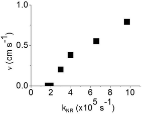 | ||
| Fig. 5 Surface quenching velocity v in thin films as a function of the non-radiative decay rate kNR in the bulk films. | ||
3.3 Influence of the refractive index of the substrate
In order to improve our understanding of the surface quenching processes, we investigated the role of the substrate on the phosphorescence of IrG1 neat films. The PL spectra on different substrates are similar and their peak shifts slightly to shorter wavelengths when decreasing the film thickness (data not shown). Fig. 6 shows the surface quenching dynamics g(t) for IrG1 neat films for different substrates. We find that the effect of the film thickness on the phosphorescence decays varies strongly with the substrate – it is weak in dendrimer films deposited on a sapphire substrate and negligible on SF15 glass. The fits to eqn (3) give values of the surface quenching velocity v which are plotted in Fig. 7 as a function of the refractive index of the substrate at 520 nm which corresponds to the maximum peak of the IrG1 PL spectrum in the solid state.30 Except for the case of ITO and to some extent PEDOT, the surface quenching velocity is found to decrease as the refractive index increases. Note that the influence of the refractive index on ν cannot be described by a simple 1/2n2 law (n being the average refractive index of the medium), which confirms that light-outcoupling does not play any significant role on the investigated quenching processes. In that context, our finding indicates that surface quenching occurs at the film-substrate interface. This behaviour can be due to different densities of trap states at the interface or more likely to the Förster-type energy transfer of the triplet excitons to the substrates, which act as quenchers.9,12 The Förster-type energy transfer rate is known to be proportional to 1/n4 where n is the refractive index of the medium31,32 and the dipole–dipole interactions can be sensitive to the boundary conditions of an interface.33–35 Taking this into account, the most plausible explanation for the observed behaviour of the phosphorescence decays would be that the energy transfer of the triplets to the quenchers located at the phosphorescent dendrimer film-substrate interface is controlled by the refractive index of substrate due to a screening of dipole–dipole interactions by the dielectric environment. Note that ITO substrates and PEDOT are commonly employed in practical OLED devices but their use can lead to an additional and alternative pathways to quenching of the excitons at the interface with the organic light-emitting layer.36,37 This is consistent with our observation that the surface quenching velocity in both cases is high despite their large refractive indices as compared with those of glass or fused silica. In particular, the strong quenching for ITO suggests that it is directly quenching excitations. This is intriguing in view of its widespread use in efficient OLEDs. However, in efficient OLEDs, the device structure is chosen to ensure that the emission occurs far from the electrodes.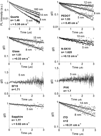 | ||
| Fig. 6 Ratio of the phosphorescence intensity g(t) measured for neat thin films of IrG1 of given thicknesses to that in the thick film on different substrates, n is the refractive index of the substrate at the PL peak. Solid lines are fits to an exponential decay and surface quenching velocities v obtained using eqn (3) are given. | ||
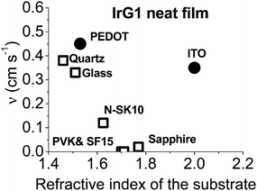 | ||
| Fig. 7 Surface quenching velocity v for IrG1 neat films as a function of the refractive index of the substrate at 520 nm. | ||
Overall, this study provides new information on the photophysics of solution-processed electrophosphorescent organic solid-state materials. With the current interest in the use of photonic materials to enhance photophysical properties, the possibility to control the energy transfer of triplet excitons to quenching sites by the selection of the substrate may offer new ways of improving light emission from iridium(III) complexes. In addition to OLEDs, the results presented in this work will be essential for the future development of high performance phosphorescent OFETs20 where the generation of triplet excitons takes place near the interface with the gate dielectric layer. It is worth noting that the refractive index of the substrate was found to not affect the photophysical properties of fluorescent bisfluorene-cored dendrimers.28 The reason why such a different behaviour was observed between phosphorescent iridium(III) complexes and fluorescent dendrimers is still not clear and should be clarified in the near future by examining the photophysical properties of other organic light-emitting materials and determining the nature of the surface quenchers. In that regard, the film thickness dependence of the dynamics of the prompt and delayed fluorescence in TADF materials could be of strong interest.
4. Conclusion
In conclusion, we observed a strong thickness dependence of the phosphorescence decays in iridium(III) complex-cored dendrimer films and modelled it by a surface quenching of the excitons at the film interface. The results show that this effect strongly depends on the exciton diffusion and is larger in materials with high non-radiative decay rate and low concentration quenching. Finally, we observed a strong influence of the refractive index of the dielectric substrate on the phosphorescence decays. This is attributed to the role played by the refractive index of the substrate on the Förster type energy transfer rate of triplet excitons to the quenching sites located at the film/substrate interface. This study provides useful new information for the development of high efficiency triplet-harvesting electroluminescent devices.Acknowledgements
We are grateful to the EPSRC of the UK for supporting this work through grants EPSRC GR/S82381/01, GR/S82398/01 and EP/J009016, and to the European Research Council of the European Union for support from grant number 321305. IDWS is a Royal Society Wolfson Research Merit Award Holder. The research data supporting this publication can be accessed at http://dx.doi.org/10.17630/30FC4852-3440-4B51-AA95-6A79313D475B.References
- M. A. Baldo, D. F. O'Brien, Y. Tou, A. Shoustikov, S. Sibley, M. E. Thompson and S. R. Forrest, Nature, 1998, 395, 151–154 CrossRef CAS.
- V. Cleave, G. Yahioglu, P. Le Barny, R. H. Friend and N. Tessler, Adv. Mater., 1999, 11, 285–288 CrossRef CAS.
- C. Adachi, M. A. Baldo and S. R. Forrest, J. Appl. Phys., 2001, 90, 5048–5051 CrossRef CAS.
- M. Ikai, S. Tokito, Y. Sakamoto, T. Suzuki and Y. Taga, Appl. Phys. Lett., 2001, 79, 156 CrossRef CAS.
- X. Yang, D. C. Müller, D. Neher and K. Meerholz, Adv. Mater., 2006, 18, 948–954 CrossRef CAS.
- K. H. Kim, S. H. Lee, C. K. Moon, S. Y. Kim, Y. S. Park, J. H. Lee, J. W. Lee, J. Huh, Y. M. You and J. J. Kim, Nat. Commun., 2014, 5, 4769 CrossRef CAS PubMed.
- Y. S. Park, S. H. Lee, K. H. Kim, S. Y. Kim, J. H. Lee and J. J. Kim, Adv. Funct. Mater., 2013, 23, 4914–4920 CrossRef CAS.
- H. Uoyama, K. Goushi, K. Shizu, H. Nomura and C. Adachi, Nature, 2014, 492, 234–238 CrossRef PubMed.
- Y. Kawamura, J. Brooks, J. J. Brown, H. Sasabe and C. Adachi, Phys. Rev. Lett., 2006, 96, 017404 CrossRef PubMed.
- R. J. Holmes, S. R. Forrest, T. Sajoto, A. Tamayo, P. I. Djurovich and M. E. Thompson, Org. Electron., 2006, 7, 163–172 CrossRef CAS.
- M. A. Baldo, C. Adachi and S. R. Forrest, Phys. Rev. B: Condens. Matter Mater. Phys., 2000, 62, 10967 CrossRef CAS.
- J. C. Ribierre, A. Ruseckas, K. Knights, S. V. Staton, N. Cumstey, P. L. Burn and I. D. W. Samuel, Phys. Rev. Lett., 2008, 100, 017402 CrossRef CAS PubMed.
- W. I. Jeong, S. Y. Kim, J. J. Kim and J. W. Kang, Chem. Phys., 2009, 355, 25–30 CrossRef CAS.
- J. C. Ribierre, A. Ruseckas, I. D. W. Samuel, S. Staton and P. L. Burn, Phys. Rev. B: Condens. Matter Mater. Phys., 2008, 77, 085211 CrossRef.
- J. C. Ribierre, S. G. Stevenson, I. D. W. Samuel, S. V. Staton and P. L. Burn, J. Disp. Technol., 2007, 3, 233–237 CrossRef CAS.
- J. C. Ribierre, C. Yates, A. Ruseckas, S. V. Staton, P. L. Burn and I. D. W. Samuel, Org. Electron., 2010, 11, 62–66 CrossRef CAS.
- J. P. J. Markham, I. D. W. Samuel, S.-C. Lo, P. L. Burn, M. Weiter and H. Bässler, J. Appl. Phys., 2004, 95, 438–445 CrossRef CAS.
- E. B. Namdas, A. Ruseckas, I. D. W. Samuel, S.-C. Lo and P. L. Burn, Appl. Phys. Lett., 2005, 86, 091104 CrossRef.
- E. B. Namdas, A. Ruseckas, I. D. W. Samuel, S.-C. Lo and P. L. Burn, J. Phys. Chem. B, 2004, 108, 1570–1577 CrossRef CAS.
- E. B. Namdas, B. B. Y. Hsu, Z. Liu, S.-C. Lo, P. L. Burn and I. D. W. Samuel, Adv. Mater., 2009, 21, 4957–4961 CrossRef CAS PubMed.
- D. F. O'Brien, C. Giebler, R. B. Fletcher, A. J. Cadby, L. C. Palitis, D. G. Lidzey, P. A. Lane, D. D. C. Bradley and W. Blau, Synth. Met., 2001, 116, 379–383 CrossRef.
- N. C. Greenham, I. D. W. Samuel, G. R. Hayes, R. T. Phillips, R. R. Kessener, S. C. Moratti, A. B. Holmes and R. H. Friend, Chem. Phys. Lett., 1995, 241, 89–96 CrossRef CAS.
- K. H. Tews, O. Inacker and H. Kuhn, Nature, 1970, 228, 278–280 Search PubMed.
- K. H. Drexhage, Prog. Opt., 1974, 12, 165–231 Search PubMed.
- W. L. Barnes, J. Mod. Opt., 1998, 45, 661–699 CrossRef CAS.
- G. L. J. A. Rikken, Phys. Rev. A: At., Mol., Opt. Phys., 1995, 51, 4906 CrossRef CAS.
- S. V. Vickers, H. Barcena, K. A. Knights, R. K. Thomas, J. C. Ribierre, S. Gambino, I. D. W. Samuel, P. L. Burn and G. Fragneto, Appl. Phys. Lett., 2010, 96, 263302 CrossRef.
- J. C. Ribierre, A. Ruseckas, P. E. Shaw, H. S. Barcena, P. L. Burn and I. D. W. Samuel, J. Phys. Chem. C, 2008, 112, 20463–20468 CAS.
- J. C. Ribierre, A. Ruseckas, I. D. W. Samuel, H. S. Barcena and P. L. Burn, J. Chem. Phys., 2008, 128, 204703 CrossRef CAS PubMed.
- S.-C. Lo, N. A. H. Male, J. P. J. Markham, S. W. Magennis, P. L. Burn, O. V. Salata and I. D. W. Samuel, Adv. Mater., 2002, 14, 975–979 CrossRef CAS.
- T. Förster, Ann. Phys., 1948, 2, 55–75 CrossRef.
- R. S. Knox and H. van Amerongen, J. Phys. Chem. B, 2002, 106, 5289–5293 CrossRef CAS.
- P. Andrew and W. L. Barnes, Science, 2000, 290, 785–788 CrossRef CAS PubMed.
- M. Hopmeier, W. Guss, M. Deussen, E. O. Göbel and R. F. Mahrt, Phys. Rev. Lett., 1999, 82, 4118–4121 CrossRef.
- G. S. Agarwal and S. D. Gupta, Phys. Rev. A: At., Mol., Opt. Phys., 1998, 57, 667 CrossRef CAS.
- J. Mei, M. S. Bradley and V. Bulovic, Phys. Rev. B: Condens. Matter Mater. Phys., 2009, 79, 235205 CrossRef.
- K. H. Yim, R. H. Friend and J. S. Kim, J. Chem. Phys., 2006, 124, 184706 CrossRef PubMed.
| This journal is © the Owner Societies 2016 |

