
 Open Access Article
 This Open Access Article is licensed under a Creative Commons Attribution-Non Commercial 3.0 Unported Licence
Formation of reworkable nanocomposite adhesives by dielectric heating of epoxy resin embedded Fe3O4 hollow spheres†
Bin
Zhao
a,
Mark
Hardiman
a,
Kevin M.
Ryan
b,
Emmet
O'Reilly
b and
Conor
McCarthy
*a
aDepartment of Mechanical, Aeronautical and Biomedical Engineering, Irish Centre for Composites Research, Materials and Surface Science Institute, University of Limerick, Limerick, Ireland. E-mail: Conor.McCarthy@ul.ie; Fax: +353 61 202944; Tel: +353 61 234334
bDepartment of Chemical and Environmental Sciences, Irish Centre for Composites Research, Materials and Surface Science Institute, University of Limerick, Limerick, Ireland
First published on 26th July 2016
Abstract
Epoxy resin (ER) thermosetting adhesives provide highly cross-linked 3-dimensional structures leading to highly stable and strong mechanical/physical performance in a wide range of bonding applications. However, such excellent physical attributes pose a significant challenge with respect to disassembly of the bonded adherends and previous disassembly methods have resulted in damage to the adherends. Hence, this paper presents a specifically engineered re-workable nanocomposite adhesive, created by embedding dielectric sensitive Fe3O4 hollow nanospheres (HNSs) in epoxy resin. This nanocomposite adhesive can be completely degraded by dielectric heating, resulting in facile disassembly of bonded adherends. FESEM and 3D Micro-CT characterisation demonstrates good dispersibility of the HNSs in cured ER, while the dielectric degradation performance and hardness/modulus were investigated by FESEM and nanoindentation. Results show that the Fe3O4 HNSs can effectively convert the microwave energy into thermal energy to significantly degrade the mechanical properties of the adhesive modulus and hardness by 83.4% and 90%, respectively. FESEM and HRTEM imaging attributes the reduction in nanocomposite adhesive properties to the formation of spatial voids nucleating from the embedded nanomaterials. Prior to dielectric heating, tensile loaded single lap-shear bonded joint tests indicated that the nanocomposite adhesive was 19.3% stronger than its neat ER adhesive counterpart due a nano-reinforcement toughening mechanism. However, after 3 minutes of dielectric heating exposure, the nanocomposite adhesive joint strength was reduced by 96.3% compared to just 18.7% for the neat ER adhesive, demonstrating the excellent re-workable performance of our new nanocomposite adhesive.
Introduction
Novel applications involving nanomaterials in polymers is a key driver of development in the field of composites engineering. Epoxy resins, also known as polyepoxides, are a class of reactive prepolymers and polymers which contain epoxide groups,1 and such materials have found widespread applications as metal coatings, electronics/electrical components, high tension electrical insulators, fibre-reinforced plastic materials and highly stable structural adhesives.1–7 Epoxy resin, as the main component of epoxy thermosetting plastics and adhesives, can provide a highly cross-linked 3-dimensional polymeric structure post curing, leading to very strong mechanical and physical properties (e.g. mechanical strength to support high stresses or loads, resistance to extreme temperatures, organic solvents and water resistance).6,7 However, as a result of this highly cross-linked structure, subsequent disassembly of epoxy bonded adherends is challenging, with significant consequences for part replacement, repair, or recycling processes. Previous attempts to disassemble bonded adherends by heat, electromagnetic induction or photo-reversibility have resulted in damage to the adherends.8–10 One approach to overcome this issue is the development of an adhesive that can be modified in such a way that it loses both its adhesive and cohesive strengths, thereby resulting in joints that can be disassembled or “unzipped” without causing any damage to the adherends. In this paper we develop such an adhesive.Previous attempts to use electromagnetic waves to degrade pure epoxy thermosetting adhesives have failed due to the poor electromagnetic absorption performance of epoxies.11–15 However, in terms of the intrinsic magnetic properties of ferrites, the electromagnetic and microwave absorption properties of Fe3O4 materials have also been attracting extensive interest, signifying their potential applications in electromagnetic stealth and shielding, reducing electromagnetic interference (EMI), and protecting information security from electromagnetic wave leaking.13–18 Additionally, the core–shell12–15 or hollow spherical16–18 morphology was beneficial to the improvement of electromagnetic absorption performance, and prior studies13–18 also revealed that magnetite (Fe3O4) was cost effective, reusable and easily recyclable (e.g. facile magnetic separation).
Here, consequently, we have specifically engineered a nanocomposite by embedding dielectric sensitive nanomaterials in epoxy resin to enable post-cure degradation by dielectric heating. The advantages of this approach is that it can allow disassembly of adherends in dielectric heating reactors, remote from the operator, with little or no damage to the adherends, providing superiority for special disassembling procedures such as large scale and high volume operations, particularly for disassembling inner, complicated or stereo-blocked surfaces.
In our approach, specifically, Fe3O4 HNSs, employed as the dielectric sensitive materials (namely, the electromagnetic receptor), were dispersed into an epoxy resin to obtain the nanocomposite adhesive. The dispersibility of Fe3O4 HNSs in the cured epoxy is characterised by field emission scanning electron microscopy (FESEM) and 3D Micro-CT. Then the cured nanocomposite adhesive was heated in a single-mode microwave reactor at 2.45 GHz and compared to a neat ER adhesive. The dielectric degradation performance and mechanical properties (i.e. hardness and modulus) of the nanocomposite and neat ER adhesives by microwave irradiation over time were further investigated by FESEM and nanoindentation characterisation. Tensile lap-shear bonded joint tests were carried out with both adhesives before and after exposure to dielectric heating for up to 3 minutes, showing that the nanocomposite adhesive performed excellently as a strong adhesive that can be re-worked easily by reducing its strength by 97% after exposure to dielectric heating.
Experimental section
Synthesis
Fe3O4 HNSs were synthesised by an improved solvothermal treatment using HMTA as a mild alkaline source (see details in the ESI†). The as-prepared Fe3O4 HNSs were dispersed into pure epoxy resin (Sigma-Aldrich) via sonication at 80 °C for 30 min. The hardeners MNA and DDSA (Sigma-Aldrich) and accelerator DMP (Sigma-Aldrich) were added into the Fe3O4 HNS embedded epoxy and dispersed by stirring followed by sonication until a uniform dispersion was obtained. The epoxy HNS composite was then applied to quartz slides and cured in a vacuum oven at 60 °C for 3 days. The cured nanocomposite sheet (25.4 mm × 25.4 mm ×1 mm) was obtained for analysis and dielectric degradation in the single mode microwave reactor CEM Discover SP with an infrared (IR) temperature sensor, as shown in Scheme 1a. For comparison, a pure epoxy resin sheet was also prepared using the same curing procedure.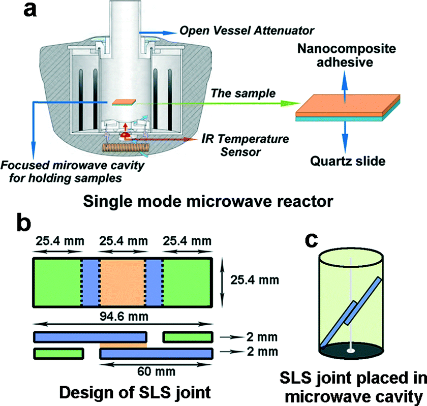 | ||
| Scheme 1 Schematic illustrations of (a) the heating procedure of cured composites (1.0 wt% Fe3O4 HNSs in epoxy resin) in the single mode microwave reactor CEM Discover SP; (b) geometrical parameters of the SLS joint; (c) the adhesively bonded SLS joint placed in the cavity of the microwave reactor for further dielectric heating investigation. | ||
Characterisation
FESEM was performed using a Hitachi SU-70 system at accelerating voltages of 10–20 kV. Transmission electron microscopy (TEM) was performed using a JEOL JEM 2100F field emission microscope equipped with an EDX facility for performing Selected Area Diffraction (SAED). X-ray diffraction (XRD) analysis was conducted using a PANalytical X'Pert PRO MRD instrument with a Cu Kα radiation source (λ = 1.5418 Å) and an X'celerator detector. 3D X-ray microscopy (XRM) was performed using a VersaXRM-500 employing a high-energy X-ray source (80 kV). The hardness and modulus of the cured nanocomposites (or pure epoxy resin), obtained before and after microwave irradiation, were characterised by nanoindentation using a Nanoindenter G200 developed by Agilent Technologies (see details in the ESI†).19A universal tensile machine (UTM, Tinius Olsen H25KS) was used to carry out the tensile shear tests20–24 at room temperature. Nanocomposites (or pure epoxy resin as a comparison) were used for bonding single-lap-shear (SLS) joints in this study. The specimen configuration and dimensions are illustrated in Scheme 1b. The substrates were highly stable epoxy plastic slides (60 mm × 25.4 mm × 2 mm) with no surface coating. 0.63 ml of uncured nanocomposites (or pure epoxy resin) was used for bonding the joints with a bond area of 25.4 mm × 25.4 mm. The total length of the bonded joints was 94.6 mm. These customised dimensions were chosen to be as close as possible to standardised adhesive joints tests,20–24 but modified so that the joints could fit in the cavity of the microwave reactor for subsequent dielectric heating, as shown in Scheme 1c (more photos are given in Fig. S1 (ESI†)).
The cured joints were then exposed to single-mode microwave irradiation at a fixed power of 100 W and a frequency of 2.45 GHz for 0–3 min. In order to ensure that the loading direction was paralleled to the bond-line, two compensation spacers (Fig. S1, ESI†) were bonded with the SLS specimens after microwave irradiation. The crosshead velocity was set at a constant velocity of 2 mm min−1.
Results and discussion
The morphology and size of the as-prepared Fe3O4 HNSs were characterised by FESEM and TEM. The FESEM image in Fig. 1a shows that the product consists of a large amount of well dispersed spherical shapes with a diameter of about 250 nm. The further magnified FESEM image in Fig. 1b demonstrates a representative broken sphere, indicating its hollow spherical morphology with a shell thickness and inner diameter of about 50 nm and 150 nm, respectively. The TEM image in Fig. 1c also proves the hollow spherical construction with similar characteristic dimensions to those seen in the FESEM images; the darker shell represents a thickness of about 50 nm. The marked area is further magnified in the HRTEM image (Fig. 1d), showing the well-defined 2D lattice fringes corresponding well with the (311) planes of the magnetite Fe3O4 polymorph (JCPDS 19-0629).13–15 The corresponding SAED pattern located in the inset of Fig. 1d confirms the single crystallinity of the as-prepared Fe3O4 HNSs.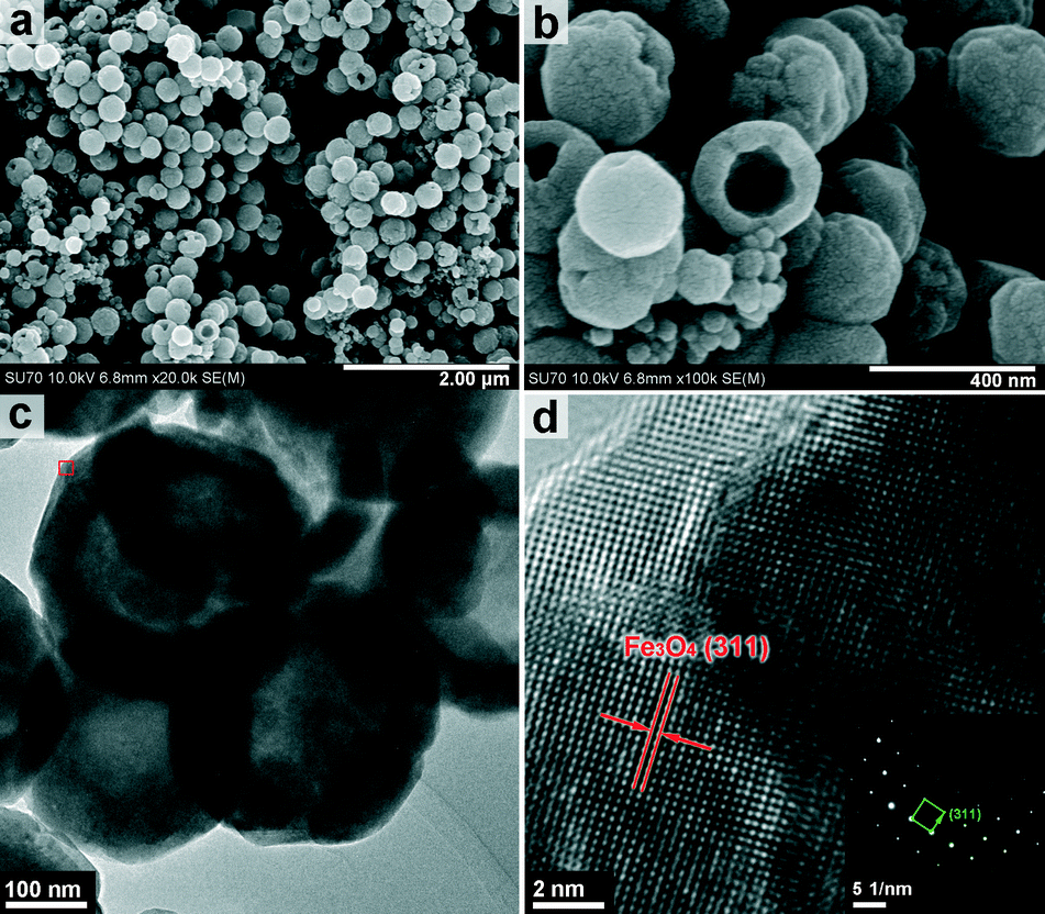 | ||
| Fig. 1 FESEM (a) and (b), TEM (c) and HRTEM (d) images of as-prepared Fe3O4 HNSs. Inset in Fig. 1d: corresponding SAED pattern. | ||
The XRD pattern in Fig. S2 (ESI†) confirms that the product obtained in the typical procedure is a Fe3O4 polymorph, in which the diffraction peaks at 2ϑ ≈ 30.1°, 35.4°, 43.1°, 56.9° and 62.5° correspond well with the (220), (311), (400), (511) and (440) lattice planes of magnetite Fe3O4 (JCPDS 19-0629) without any other impurity.
Fig. 2 shows the dielectric heating performance of the nanocomposites and pure epoxy resin exposed to microwave irradiation at 100 W at 2.45 GHz. Interestingly, for the nanocomposite the temperature increases rapidly from 0 (C0) to 1.5 (C1.5) min, and thereafter the rate of increase slows, with the temperature reaching 239 °C after 2 min. At this point the temperature increases almost linearly until it reaches an endothermic peak at 277 °C between 2.5 and 3 min (precisely at 168 s), probably due to a severe structural (or morphological) collapse that occurred here. Thereafter, the temperature increased slowly, reaching 292 °C at 3 min (C3). In contrast, the pure epoxy resin temperature increases almost linearly, reaching 180 °C at 3 min (E3).
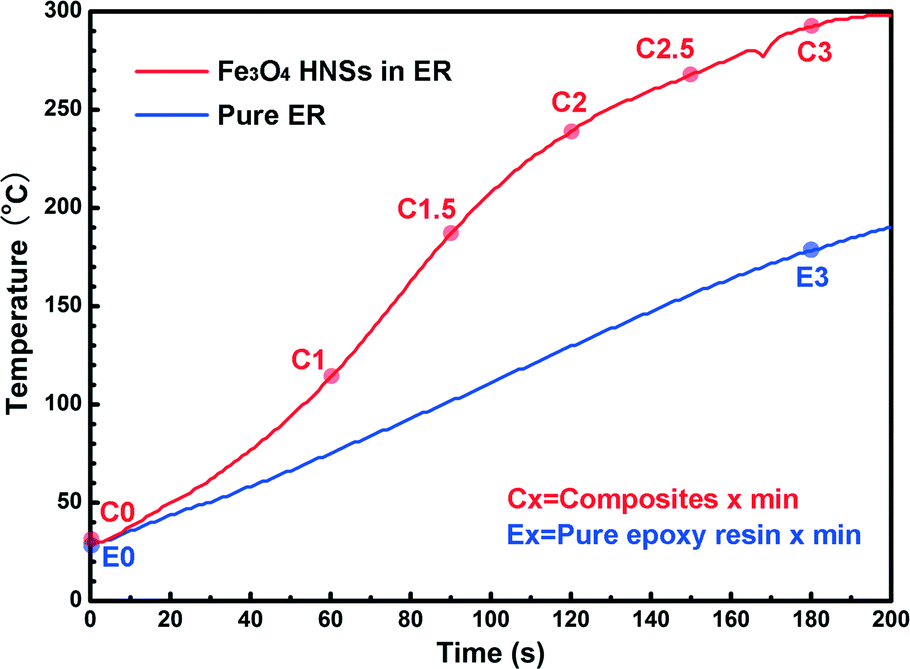 | ||
| Fig. 2 Heating temperature as a function of time for the nanocomposite adhesive and pure epoxy resin under single-mode microwave irradiation at 100 W, 2.45 GHz. | ||
Before microwave irradiation, the smooth sectioned surface of the cured pure epoxy resin is shown in FESEM images of Fig. S3a and b (ESI†). After the single mode microwave irradiation at 100 W, 2.45 GHz for 3 min, the section surface is still very smooth without any morphological damage, as shown in Fig. S3c and d (ESI†).
In contrast, Fig. 3 shows extensive damage forming over time in the nanocomposite adhesive sheet (1.0 wt% Fe3O4 HNSs in epoxy resin) when exposed to the same levels of irradiation. Fig. 3a shows a global FESEM image in low magnification before any irradiation, signifying that the Fe3O4 HNSs are embedded in the cured epoxy resin with good dispersity. This is also confirmed by the magnified image in Fig. 3b, which indicates that the Fe3O4 HNSs (white dots) are spread throughout the epoxy with a distance between clusters of approximately 5–10 μm. The further magnified FESEM image in Fig. 3c shows HNS aggregation and some of them are broken hollow spheres that exhibit an equivalent size of about 250 nm, which compares well with the results shown in Fig. 1. The FESEM image in Fig. 3d shows some tiny holes and slight cracks are generated close to the Fe3O4 HNSs in the nanocomposite adhesive sheet after 1 minute of microwave exposure. After 1.5 minutes, more holes with sizes of about 200 nm are generated at the positions of Fe3O4 HNSs, as shown in Fig. 3e, indicating that the Fe3O4 HNSs are nucleation points for degradation. Hollow cavities, with a size of about 1–2 μm, are evident at 2 min exposure, as shown in Fig. 3f.
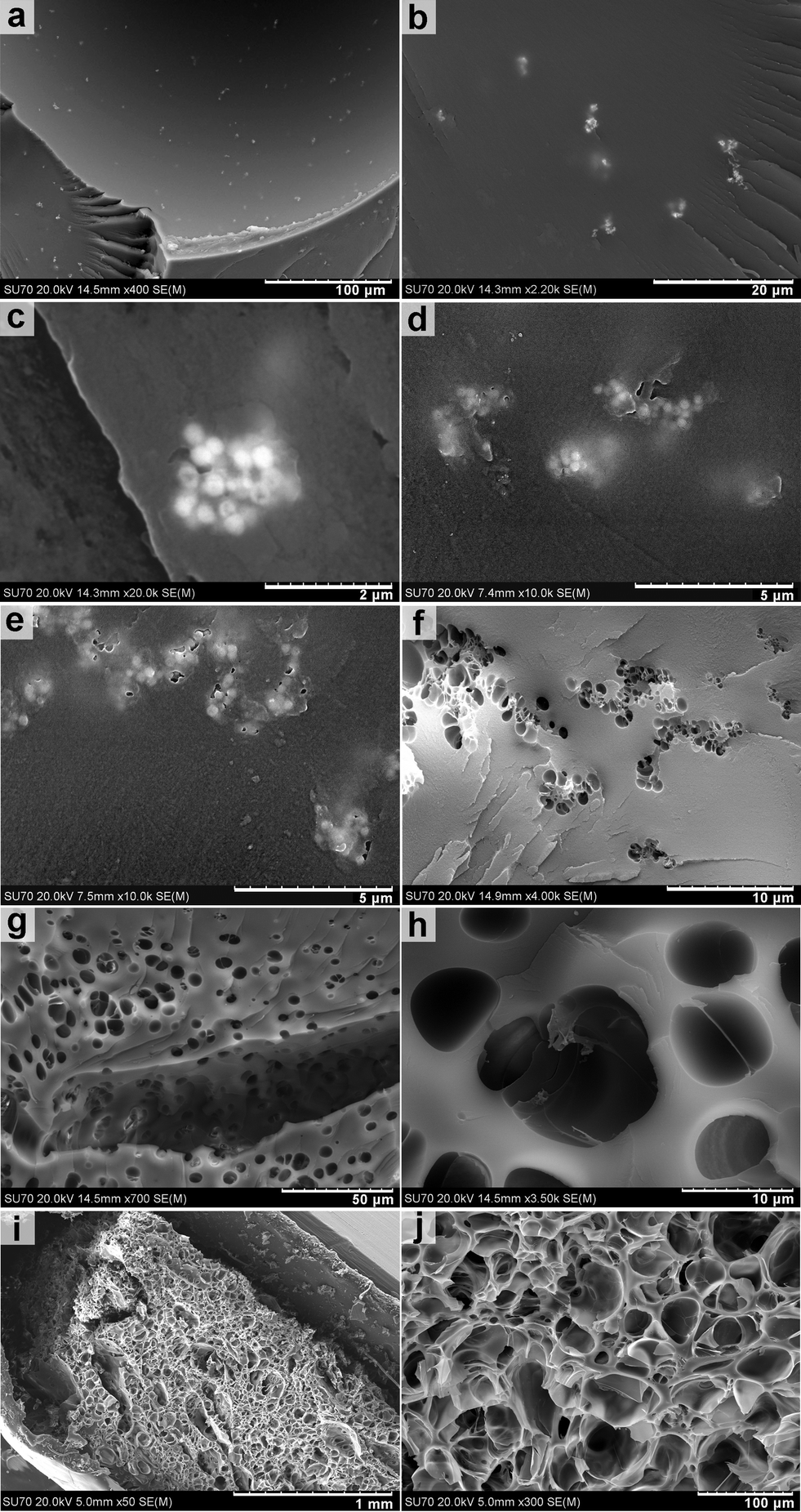 | ||
| Fig. 3 FESEM images of the section facture of the cured nanocomposite adhesive sheet (1.0 wt% Fe3O4 HNSs in epoxy resin) without microwave irradiation (a–c), with single-mode microwave irradiation at 100 W for 1 (d), 1.5 (e), 2 (f), 2.5 (g & h) and 3 (i & j) min. | ||
After 2 min exposure, the degradation process accelerates with numerous hollow cavities evident. The cavities were observed to spread all over the section surface, as shown in Fig. 3g. The vertical fracture in this image demonstrates that the hollow cavities are not surface confined and are also generated within the nanocomposite adhesive sheet. The magnified FESEM image shown in Fig. 3h shows that the hollow cavities are approximately 5–10 μm in diameter, significantly greater than the initial size of Fe3O4 HNS clusters (1–2 μm). The distance between the centre of the hollow cavities is about 5–10 μm, providing further evidence that the degradation commenced at the Fe3O4 HNS clusters. As shown in Fig. 3i, the morphology of the cured nanocomposite adhesive sheet was significantly altered after 3 min of irradiation exposure, resulting in a sponge-like fully voided hollow networked structure. The corresponding magnified image shown in Fig. 3j exhibits a hollow texture with the cavity size up to 100 μm.
Fig. 4a shows 3D Micro-CT characterisation results where the internal morphologies in three spatial dimensions of the cured nanocomposite adhesive before microwave irradiation indicate that the Fe3O4 HNSs (black) are well dispersed in 3D epoxy resin substrates (white). This is further highlighted by the orthoslice shown in Fig. 4b. The internal morphologies and corresponding orthoslice after 3 minutes of exposure to dielectric heating are shown in Fig. 4c and d, respectively, and indicate that the 3D sponge-like morphologies are well distributed hollow cavities with a diameter of up to 100 μm, agreeing well with Fig. 3j. For comparison, 3D Micro-CT characterisation results for cured pure epoxy resin with/without microwave irradiation are given in Fig. S4 (ESI†), where it is shown that a smooth and uniform epoxy resin substance is maintained after microwave irradiation, with little damage evident.
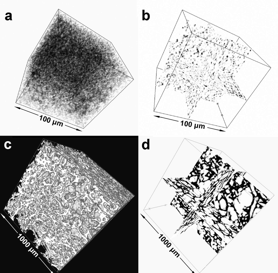 | ||
| Fig. 4 3D X-ray computed tomography of the cured nanocomposite adhesive (1.0 wt% Fe3O4 HNSs in epoxy resin) before (a & b) and after (c & d) 3 min microwave irradiation at 100 W, 2.45 GHz. (b) and (d) are the corresponding orthoslices for (a) and (c), respectively. | ||
Previous work reported that magnetite Fe3O4 nanocomposites showed good microwave absorption performance.12–18 The hollow spherical nature of our Fe3O4 nanoparticles likely improved the performance in the epoxy resin as a degradation enhancer here, similar to previous reports on conductive polymer hollow microspheres.18 It is shown above that the hollow cavities grew over time under microwave irradiation, and then merged with each other to form substantially larger micrometre sized cavities, finally forming the hollow network structure shown in Fig. 3j, 4c and d. It can thus be concluded that the dielectric sensitive material (Fe3O4 HNSs) acted as a very effective electromagnetic receptor that converted the dielectric energy into heat in the epoxy resin, degrading it over time, resulting in the formation of hollow cavities.
In order to test the applicability of the developed Fe3O4-ER nanocomposite as a “reworkable adhesive”, a series of mechanical characterisation tests were performed before and after microwave irradiation. Fig. 5 shows nanoindentation hardness and modulus measurements as a function of depth (0–5000 nm), using the Continuous Stiffness Measurement (CSM) technique for cured pure epoxy resins (E0, E3) and nanocomposite adhesives (C0–C3) with different dielectric heating times. The indentation data is very noisy for the first 1000 nm of indentation depth due to the surface roughness on the samples and low load levels, and so average data over indentation depths of 1000–5000 nm is used as it has essentially converged. The average hardness and modulus values for pure epoxy resin with no irradiation exposure (E0) are 0.16 GPa and 3.3 GPa, respectively. After 3 min of microwave irradiation, the average hardness and modulus are essentially maintained at 0.16 GPa and 3.4 GPa, indicating that no obvious degradation of the mechanical properties has occurred. The average hardness and modulus values for the non-irradiated nanocomposite adhesive (C0) are 0.20 and 3.6 GPa, respectively, signifying significant improvements over the neat epoxy case, and these properties were maintained for up to 1 min of dielectric heating exposure (C1). However, after this point the properties were observed to decrease rapidly, with the hardness reduced to 0.17 GPa and the modulus to 3.0 GPa at 2 min exposure time (C2). The most likely cause of this is the formation of 5–10 μm sized cavities shown in Fig. 3h. At 3 min exposure (C3), the hardness and modulus were severely decreased by 83.4% and 90% to only 0.02 GPa and 0.6 GPa, respectively, indicating that the nanocomposite adhesive was almost completely degraded by the dielectric heating. For reference, the corresponding nanoindentation sites19,25 are shown in Fig. S5 (ESI†), where it can be seen that for pure epoxy resin a smooth flattened indentation surface still exhibited little damage after dielectric heating. In contrast, the indentation sites of nanocomposite adhesives are seen superimposed onto the voided surfaces especially at 2 or 3 min exposure time, which corresponds well with the FESEM and 3D Micro-CT results above.
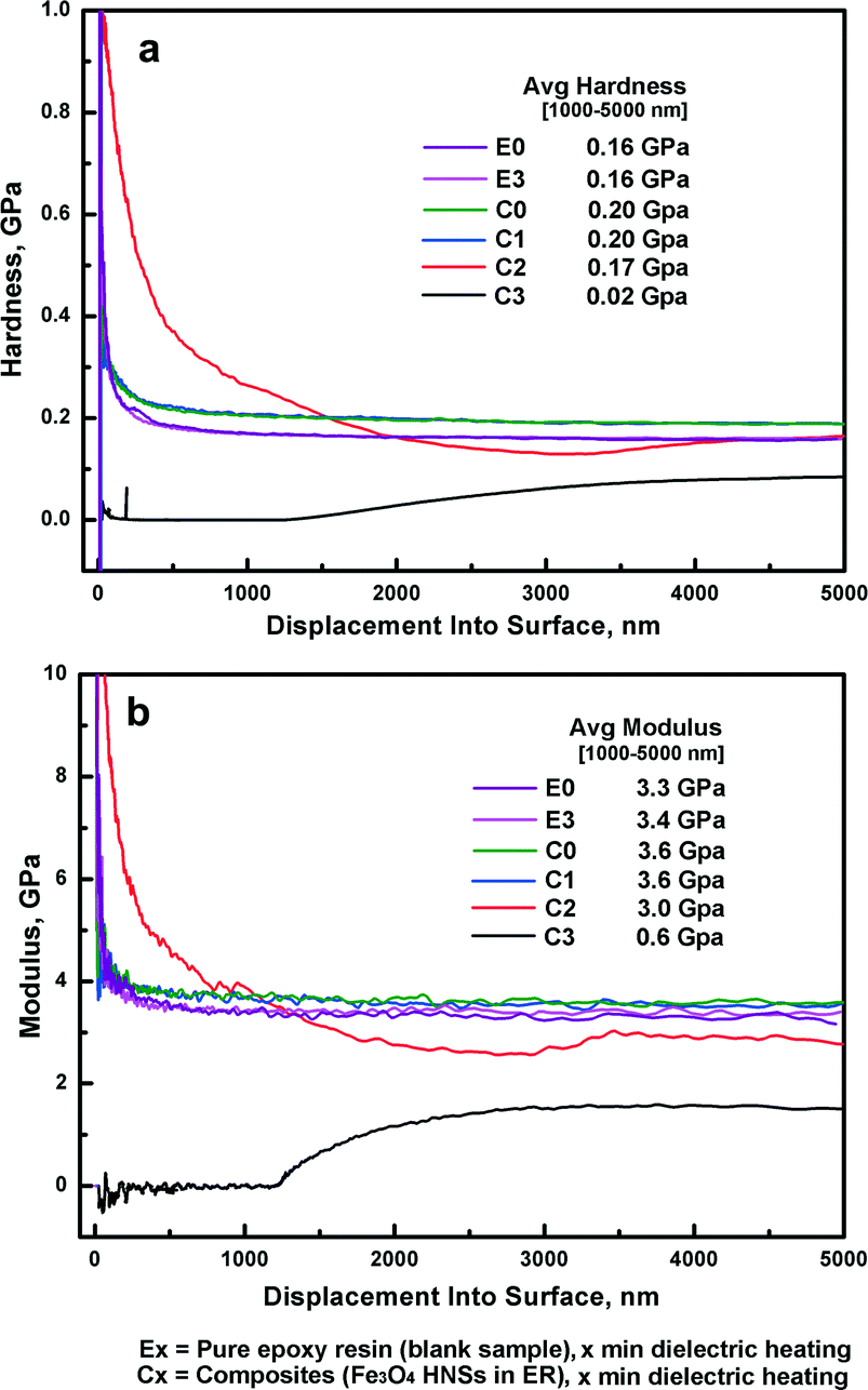 | ||
| Fig. 5 Hardness (a) and modulus (b) as a function of depth for indentations into various cured nanocomposite adhesives and pure epoxy resin with different dielectric heating times. | ||
The final step in this work is to establish if the degradations in mechanical properties observed above are repeated when the nanocomposite adhesives are used in bonded joint applications. Fig. 6 shows the ultimate strength of single-lap shear (SLS) tension loaded joints bonded with both neat epoxy resins (JE0, JE3) and nanocomposite adhesives (JC0–JC3) at increasing microwave irradiation time, which corresponds to the load–displacement curves shown in Fig. S6 (ESI†). Interestingly, the ultimate joint strength (MPa, at the failure point20–23) of the SLS joints increased from 7.24 MPa (JE0) to 8.64 MPa (JC0) by the addition of the Fe3O4 HNSs into the bonding epoxy adhesive, most likely due to a toughening mechanism observed by introducing impurities into epoxy adhesives.20 After 3 min of microwave irradiation, the strength of the SLS joints bonded by the pure epoxy, while reduced by 18.8%, still remains high at 5.88 MPa (JE3), demonstrating that microwave irradiation is not sufficient alone to decouple or “unzip” these bonded adherends. The strength of SLS joints bonded by nanocomposite adhesives remains almost constant up to 1 min of exposure (JC0–JC1), which is in fact useful as these joints if subjected to unintended or malice microwave energy would not immediately debond. However, after this point the joint strength decreases linearly and at 3 min exposure time it decreased by 96.3% to 0.31 MPa. This significant decrease in strength indicates that the bonding strength is overwhelmingly weakened by the application of dielectric heating, to the point that application of any further mechanical load (even low hand pressure) completely debonded the adherends.
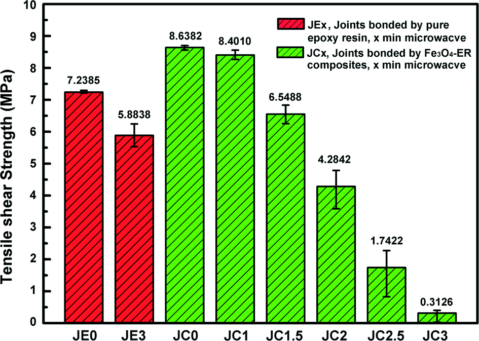 | ||
| Fig. 6 The tensile shear strength of the adhesively-bonded single lap-shear (SLS) joints as a function of microwave irradiation time at 100 W, 2.45 GHz. | ||
Conclusions
In conclusion, we have engineered a reworkable nanocomposite based adhesive by embedding the dielectric sensitive nanomaterials Fe3O4 hollow nanospheres (HNSs) in epoxy resin. The developed nanocomposite adhesive is highly sensitive to dielectric heating, resulting in significant degradation of mechanical properties after an exposure time of less than 3 minutes. The dielectric heating performance of the composite adhesive was investigated by microwave irradiation at fixed power over time. FESEM and 3D Micro-CT results indicated that the dielectric sensitive materials, Fe3O4 HNSs, were well dispersed in the cured epoxy resin and act as electromagnetic receptors to effectively convert the microwave energy into thermal energy to significantly degrade the modulus and hardness by 83.4% and 90%, respectively, as a result of growing major voids in the adhesive that nucleate at the nano-reinforcement sites. Before exposure to dielectric heating, tensile loaded SLS joints bonded by the nanocomposite adhesive were in fact 19.3% stronger than those bonded using just the neat ER adhesive. After 3 minutes of dielectric heating exposure, the strength of the nanocomposite adhesive joint was reduced by 96.3%, compared to just 18.7% for the neat ER adhesive, thus demonstrating the excellent re-workable performance of our new composite adhesive.Acknowledgements
This work was supported by Science Foundation Ireland (SFI) under Investigators Project (IvP) 13/IA/1833, “Fastener-less Joining Technologies for High Performance Hybrid Composites-Metal Structures”. This work was also conducted under the framework of the Irish Government's Programme for Research in Third Level Institutions Cycle 5, with the assistance of the European Regional Development fund. The authors also acknowledge Mr. Michael Byrne (Dept. Mechanical Aeronautical and Biomedical Engineering, University of Limerick, Ireland) for 3D X-ray microscopy (XRM) test.References
- H. Q. Pham and M. J. Marks, Epoxy Resins, Ullmann's Encyclopedia of Industrial Chemistry, 2005 Search PubMed.
- A. M. Asiri, M. A. Hussein, B. M. Abu-Zied and A.-E. A. Hermas, Polym. Compos., 2015, 36, 1875–1883 CrossRef CAS.
- Z.-M. Dang, B. Zhang, J. G. Li, J.-W. Zha and G.-H. Hu, J. Appl. Polym. Sci., 2012, 126, 815–821 CrossRef CAS.
- K. Suggs and X. Q. Wang, Nanoscale, 2010, 2, 385–388 RSC.
- X. Zhang, Q. L. He, H. B. Gu, H. A. Colorado, S. Y. Wei and Z. H. Guo, ACS Appl. Mater. Interfaces, 2013, 5, 898–910 CAS.
- R. Rohini, K. Lasitha and S. Bose, J. Mater. Chem. C, 2016, 4, 352–361 RSC.
- T. Semoto, Y. Tsuji and K. Yoshizawa, J. Phys. Chem. C, 2011, 115, 11701–11708 CAS.
- M. Mund, J. Brodhun, F. Fischer and K. Dilger, 36th. Annual Meeting of the Adhesion Society, Daytona Beach and FL and March 03.-06. 2013, The Adhesion Society, 2013 Search PubMed.
- J. M. Boyne, E. J. Millan and I. Webster, Int. J. Adhes. Adhes., 2001, 21, 49–53 CrossRef CAS.
- J. H. Aubert, J. Adhes., 2003, 79, 609–616 CrossRef CAS.
- R. C. Che, L. M. Peng, X. F. Duan, Q. Chen and X. L. Liang, Adv. Mater., 2004, 16, 401–405 CrossRef CAS.
- J. W. Liu, J. J. Xu, R. C. Che, H. J. Chen, M. M. Liu and Z. W. Liu, Chem. – Eur. J., 2013, 19, 6746–6752 CrossRef CAS PubMed.
- J. W. Liu, R. C. Che, H. J. Chen, F. Zhang, F. Xia, Q. S. Wu and M. Wang, Small, 2012, 8, 1214–1221 CrossRef CAS PubMed.
- J. J. Xu, J. W. Liu, R. C. Che, C. Y. Liang, M. S. Cao, Y. Li and Z. W. Liu, Nanoscale, 2014, 6, 5782–5790 RSC.
- M. Yu, C. Y. Liang, M. M. Liu, X. L. Liu, K. P. Yuan, H. Cao and R. C. Che, J. Mater. Chem. C, 2014, 2, 7275–7283 RSC.
- H. L. Lv, G. B. Ji, W. Liu, H. Q. Zhang and Y. W. Du, J. Mater. Chem. C, 2015, 3, 10232–10241 RSC.
- Y. C. Du, W. W. Liu, R. Qiang, Y. Wang, X. J. Han, J. Ma and P. Xu, ACS Appl. Mater. Interfaces, 2014, 6, 12997–13006 CAS.
- R. Pang, X. J. Hu, S. Y. Zhou, C. H. Sun, J. Yan, X. M. Sun, S. Z. Xiao and P. Chen, Chem. Commun., 2014, 50, 12493–12496 RSC.
- M. Hardiman, T. J. Vaughan and C. T. McCarthy, Composites, Part A, 2015, 68, 296–303 CrossRef CAS.
- P. Jojibabu, M. Jagannatham, P. Haridoss, G. D. J. Ram, A. P. Deshpande and S. R. Bakshi, Composites, Part A, 2016, 82, 53–64 CrossRef CAS.
- Y. Boutar, S. Naïmi, S. Mezlini and M. B. S. Ali, Int. J. Adhes. Adhes., 2016, 67, 38–43 CrossRef CAS.
- F. Zhang, X. Yang, H.-P. Wang, X. W. Zhang, Y. Xia and Q. Zhou, Int. J. Adhes. Adhes., 2013, 44, 130–137 CrossRef CAS.
- P. N. B. Reis, J. A. M. Ferreira and F. Antunes, Int. J. Adhes. Adhes., 2011, 31, 193–201 CrossRef CAS.
- K. Naito, M. Onta and Y. Kogo, Int. J. Adhes. Adhes., 2012, 36, 77–85 CrossRef CAS.
- U. Ramamurty and J.-I. Jang, CrystEngComm, 2014, 16, 12–23 RSC.
Footnote |
| † Electronic supplementary information (ESI) available: Experimental details, XRD, FESEM, 3D micro-CT, nanoindentation sites, etc. See DOI: 10.1039/c6ce01359g |
| This journal is © The Royal Society of Chemistry 2016 |