
 Open Access Article
 This Open Access Article is licensed under a Creative Commons Attribution-Non Commercial 3.0 Unported Licence
Experimental and theoretical charge density assessments for the 4-perfluoropyridyl- and 4-perflurophenyl-1,2,3,5-dithiadiazolyl radicals†
Sławomir
Domagała
*a and
Delia A.
Haynes
 b
b
aBiological and Chemical Research Centre, Chemistry Department, University of Warsaw, Żwirki i Wigury 101, 02-089 Warszawa, Poland. E-mail: slawdom@chem.uw.edu.pl
bDepartment of Chemistry and Polymer Science, Stellenbosch University, P. Bag X1, Matieland, Stellenbosch, 7602, Republic of South Africa
First published on 8th August 2016
Abstract
The results of an experimental density analysis of 4-perfluoropyridyl-1,2,3,5-dithiadiazolyl (NF-radical) are presented and compared with the previously reported analysis of the related 4-perfluorophenyl-1,2,3,5-dithiadiazolyl (F-radical). Both the NF- and F-radicals form dimers in their crystal lattice. The strong interaction between sulfur atoms in the dimers is confirmed by the high values of the electron density at the bond critical points. Some additional bond paths relating to weaker interactions are also observed in the dimers, notably between carbon atoms and between F and N atoms. For both radicals, the spin density is almost entirely located on the nitrogen and sulfur atoms of the dithiadiazolyl ring. However, the values of the spin density are higher in the case of the NF-radical, which may result in stronger interactions between sulfur atoms in the dimers. The electron density derived properties from the experimental and theoretical multipolar models are in fairly good agreement.
Introduction
Over the last few decades much work has been done to design materials with potential applications as new molecular magnets or organic conductors. The thiazolyl radicals are one of the most promising families of compounds due to their remarkable thermal and kinetic stability and the occurrence of ferromagnetic ordering at low temperatures in some cases.1–3Unfortunately, the vast majority of these compounds have a tendency to dimerize in the solid state, resulting in a loss of paramagnetic character. To date, only a few examples of monomeric dithiadiazolyl radicals have been discovered in the solid state.2–6 Much effort has been committed to understanding the nature of the dimerization interaction and to prevent unfavorable Peierls distortions (see D. A. Haynes7 and references therein). In some cases bulky substituents are introduced to the system in order to cause steric hindrance and thus prevent the system from dimerizing.6,8 There have also been attempts to weaken the interactions in co-facial dimers by attaching different substituents to the dithiadiazolyl ring, largely perfluorophenyl substituents.2,3 Perfluorophenyl substituents often result in a large twist angle between the dithiadiazolyl ring and the substituent, thus hindering dimerization. Significant effort has also been focused on understanding the precise nature of the interaction between molecules within the dimer. When these compounds were first characterized in the 1980s, they were described as dimeric molecules, [RCN2S2]2, containing two long S–S bonds, i.e. a four-centre two-electron bond.9 By 1993, Cordes et al. were describing this dimerization as an interaction between the singly occupied molecular orbitals (SOMOs) on each radical, which was confirmed computationally.10 Recently, this type of interaction has been referred to as pancake bonding,11–13 which refers to a multi-centre two-electron bond between the two radicals in the dimer. It is clear from both experimental and computational studies that the dimerization energy is low, and the dimers readily dissociate into monomers in solution, as evidenced by the isotropic five-line EPR spectra obtained for these molecules. It is also apparent that dimerization in the solid state can be suppressed by the introduction of appropriate competing intermolecular interactions, resulting in monomers2–6 or thermally accessible triplet states.14 It is important to further understand the nature of this dimerization interaction, and experimental charge density analysis is a revealing tool in this regard.
In this manuscript we discuss the differences in electron density distribution in 4-perfluoropyridyl-1,2,3,5-dithiadiazolyl (NF-radical) and perfluorophenyl-1,2,3,5-dithiadiazolyl (F-radical) using high resolution crystallographic methods. We have previously been interested in investigating co-crystals of 1,2,3,5-dithiadiazolyl radicals,15,16 which led us to investigate the experimental charge density of one of the known co-crystals. The intention with the current study was to extend this work to investigate the second known co-crystal between two dithiadiazolyl radicals, which is a co-crystal of 4-perfluoropyridyl-1,2,3,5-dithiadiazolyl and phenyl-1,2,3,5-dithiadiazolyl. Despite numerous attempts we were unable to grow crystals of this material suitable for the collection of high resolution X-ray diffraction data. However, suitable crystals of NF-radical were obtained. We have thus studied this material in detail, with the eventual aim of shedding light on the intra-dimer interactions in these systems, such that novel co-crystals or materials with reduced dimerization energies can be designed.
The crystal structure of the NF-radical has been previously reported (CSD refcode ZADVAB, personal communication); however this earlier study was carried out at room temperature. The high resolution study carried out here allows us to compare the electron density properties derived from the experimental and theoretical multipolar models for these two radicals. The strength of the intra-dimer interactions in the NF-radical and F-radical has been analyzed using the multipolar approach as well as quantum chemical calculations. The lattice energy for these homodimeric systems is compared to those of the heterodimer complexes containing PhCN2S2 (H-radical, HNF-radical).15,16 A schematic representation of the compounds studied is given in Scheme 1.
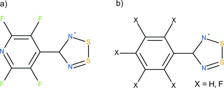 | ||
| Scheme 1 Schematic representation of 1,2,3,5-dithiadiazolyl radicals: (a) 4-perfluoropyridyl-1,2,3,5-dithiadiazolyl (NF-radical), (b) 4-perfluorophenyl-1,2,3,5-dithiadiazolyl (F-radical), X = F; 4-phenyl-1,2,3,5-dithiadiazolyl (H-radical), X = H. The co-crystal of NF-radical and H-radical is abbreviated as HNF-radical, whereas the co-crystal of F-radical and H-radical is labeled as HF-radical. | ||
Experimental and computational details
Synthesis of radicals
The synthesis of the NF-radical has been previously reported.16 Suitable crystals were prepared by sublimation in vacuo at 110 °C.X-ray crystallography
High resolution single crystal diffraction experiments were performed for the NF-radical sample using a Bruker APEX II ULTRA diffractometer with a TXS rotating anode (Mo Kα radiation), multilayer optics, and an Oxford Cryostream low temperature attachment at 90 K. A suitable crystal sample was attached to a cryogenic nylon loop, mounted on a goniometer head and positioned at 50 mm from the detector. A complete set of reflections was collected with an average redundancy above 10 up to 1.168 Å−1 resolution. The exposure times were varied between 20 and 60 seconds depending on the theta angle of the detector. The determination of the unit cell parameters and integration of the raw images were performed using the APEX2 suite of programs (integration was carried out with SAINT).17 The multiscan absorption correction, scaling, and merging of reflection data were carried out with SORTAV.18,19 Data collection statistics are gathered in Table 1. The crystal structure was solved using the SHELX program20 and was initially refined within SHELX and Olex221 using the independent atom model (IAM). In the case of the F-radical the raw data were taken from a previous publication.22 For both data sets (F-radical and NF-radical) different data reduction schemes were tested using SORTAV and SADABS.17 However, in the case of the F-radical, data reduction with SADABS gave a better model and final statistics.| Empirical formula | C6F4N3S2 |
| Fw (g mol−1) | 254.21 |
| Temp (K) | 90 |
| Crystal system | Monoclinic |
| Space group | C2/c |
| a (Å) | 17.781(2) |
| b (Å) | 9.626(1) |
| c (Å) | 11.346(1) |
| α° | 90 |
| β° | 125.713(2) |
| γ° | 90 |
| Volume (Å3) | 1576.8(3) |
| Z | 8 |
| ρ calc (mg mm−3) | 2.142 |
| μ (mm−1) | 0.709 |
| F(000) | 1000 |
| Reflns collected | 90![[thin space (1/6-em)]](https://www.rsc.org/images/entities/char_2009.gif) 319 319 |
| Independent reflns | 9970 |
| Max sin[θ/λ] (Å−1) | 1.168 |
| R int (%) | 3.14 |
Theoretical calculations
Quantum calculations for the NF-radical and its co-crystal with 4-phenyl-1,2,3,5-dithiadiazolyl (HNF-radical) were performed using the Gaussian 0923 and Crystal 0924,25 packages. The experimental structure of HNF-radical16 (refcode YIMNIT) was taken from the Cambridge Structural Database26 version 5.36 (Nov. 2014 update). The X–H distances for the HNF-radical were elongated to average neutron distances27 prior to further quantum calculations in order to facilitate comparison with the high resolution structures. The program CLUSTERGEN28 was used for the generation of dimers from the crystallographic structures of radicals and the elongation of X–H distances before further quantum calculations. The Gaussian 09 package was used for the energy calculations of monomers and dimers of dithiadiazolyl radical systems in vacuo. A total spin of ½ was imposed on monomers, whereas singlet or triplet configurations were used for the parallel and antiparallel dimers, respectively. Interaction energy calculations were performed using the UB97D functional29 with 6-31G** and 6-311++G** basis sets. The Crystal 09 package was used for lattice energy computations in periodic boundary conditions. In this case, the UB3LYP functional30,31 with the 6-31G** basis set32 was used. The B3LYP functional was augmented with an empirical dispersion correction.29,33 The relaxed potential energy scan (PES) for the NF-radical was performed using Gaussian with the UB3LYP functional and the 6-31G** basis set.Dipole moments were derived from the multipole populations using the formulae given in the works of Spackman34 and Coppens35 and were calculated using the VMoPro module, a part of the MoPro package.36,37 The dipole moment was computed with respect to the center of mass of the molecule under consideration. The integrated charges from QTAIM (Quantum Theory of Atoms in Molecules) theory38 were calculated using the WinXPRO package.39 Electrostatic interaction energies were calculated in VMoPro using the numerical integration method on a spherical grid around involved molecules. The Gauss–Chebyshev40 and Lebedev and Laikov quadratures41 were used for the radial and angular parts, respectively. Radial coordinates and weights were remapped using the formula of Treutler and Ahlrichs.42 The interaction energy values were computed as the product of the integral over the electron density of one molecule and the electrostatic potential of the second molecule. Various statistical analyses were performed on 3D grids of the deformation density and the electrostatic potential (ESP). The grids were created in the VMoPro program with a 0.1 Å sampling step and with a margin around all atoms equal to 3 Å and 4 Å for deformation density and ESP grids, respectively. In the case of ESP, the surface statistics43,44 were calculated on the Hirshfeld surface.45,46 Visualizations of density-derived properties were created using the MoProViewer program.47
Multipolar refinement
The multipolar refinements of the NF-radical were performed using the MoPro software36,37 within the Hansen–Coppens multipolar formalism48 in a stepwise manner as described in previous work.22 The initial geometry and thermal parameters were taken from the IAM refinement. The refinement was based on F and all the reflections were used. The maximum resolution of the data set was limited to 1.137 Å−1 in order to keep ∼100% completeness for the NF-radical. The multipolar expansion was truncated at the hexadecapole level for sulfur and the octupole level for the remaining atoms. The anharmonic motion parameters in the form of the Gram–Charlier (GC) expansion up to the third order were applied to the sulfur atoms. The GC expansion imposed on the sulfur atoms improved the model considerably as in the case of our previous work.22 We have also tested several different models including anharmonic expansion for fluorine atoms, though no significant improvement was observed. The κ′ values for the fluorine and sulfur atoms were constrained to the average values obtained from the theoretical multipole model based on the experimental geometry. Some multipole symmetry and equivalence kappa constraints were used to reduce the number of refined parameters.In the case of the F-radical, the initial multipolar model was taken from the previous publication and the new refinements were performed using the same cutoff resolution as for the NF-radical (1.137 Å−1) to allow a consistent comparison with the NF-radical. No I/σ(I) cutoff was used. The same multipolar expansion level and a similar type of constraints as those used for the NF-radical were applied.
During the course of the multipolar refinement several multipolar models were assessed. The final models selected for the NF-radical and F-radical have the most featureless residual density maps, and the electrostatic properties appear to be realistic and compatible with the previous analysis.22 The multipolar statistics for the final models are presented in Table 2. The most prominent maxima of unmodelled residual density are located close to the N and S atoms (Fig. S1†). The highest peak and hole are equal to 0.32/−0.25 e Å−3 and 0.27/−0.17 e Å−3 for the NF-radical and F-radical, respectively. The fractal density analysis49 supports the overall good quality of the final models (Fig. S2†).
| NF-radical | F-radical | |
|---|---|---|
| Resolution (Å−1) with completeness ∼99% | 1.137 | 1.137 |
| GOF on F2 | 0.926 | 1.919 |
| Final R indexes (%) | R 1 (F) = 1.947 | R 1 (F) = 1.340 |
| wR2 (F) = 1.766 | wR2 (F) = 1.259 | |
| N obs/Nparams | 9721/262 | 10313/271 |
| Largest diff. peak/hole (e Å−3) | 0.32/−0.25 | 0.27/−0.17 |
Multipolar refinement based on the theoretical structure factors was conducted for both the NF-radical and F-radical structures to serve as reference points. The theoretical structure factors were prepared in the following way. A set of unique Miller indices were generated for the NF-radical and F-radical structures using the segment description approach50,51 up to 1.4 Å−1 reciprocal resolution. The theoretical structure factors were generated from the sets of prepared indices and the previously computed wave functions using the XFAC option in Crystal09. During the multipolar refinement, a 1.137 Å−1 resolution cutoff was applied in order to have the same resolution as for the experimental data. The same multipolar level was applied as in the experimental models. However, no constraints were imposed on the multipolar parameters and all multipolar parameters were refined freely. The scale factor was not refined.
Details regarding the refined parameters for all the final models are given in the ESI† in Tables S1 and S2.
Results and discussion
Crystal structure
The structure of the NF-radical has already been reported.16 A single molecule of NF-radical with atom labels and thermal ellipsoids is presented in Fig. 1. The geometry of the radical molecule after the multipolar model refinement is not much different from the reported one. Generally, almost all bonds are slightly shorter in the case of the high resolution structure, but the molecular conformation is almost the same as indicated by the small values of RMS deviation (∼0.039 Å) as calculated in Mercury.52,53 The volume is slightly decreased from 1601 Å3 to 1576 Å3 due to the different temperatures of data acquisition (RT vs. 90 K).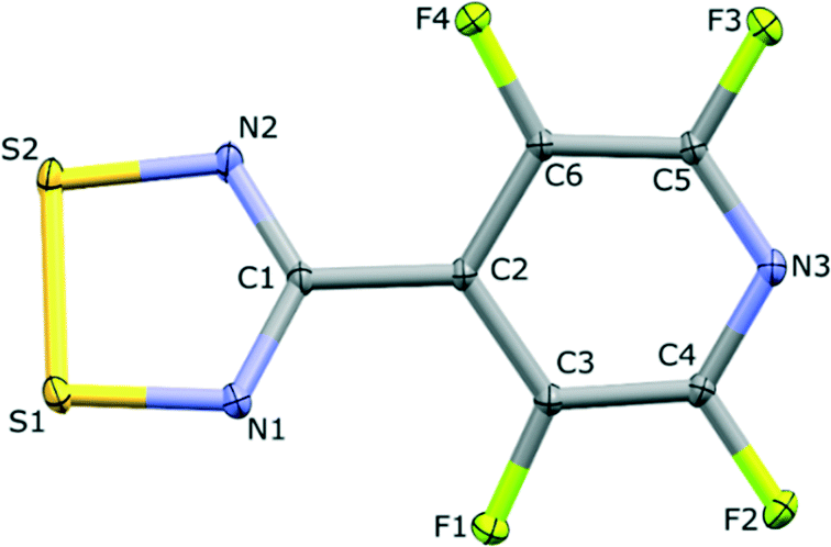 | ||
| Fig. 1 One molecule of NF-radical. Thermal ellipsoids are drawn at 50% probability level. | ||
The NF-radical forms a cis-oid dimer with a pair of close S⋯S contacts (Fig. 2a). These dimers are linked to chains via S⋯N close contacts. Chains stack on top of one another in an antiparallel fashion, such that there are also antiparallel pairs of molecules in the structure (Fig. 2b). The overall packing pattern is essentially the same as that of the F-radical structure, and in fact the co-crystal between the NF-radical and the H-radical (HNF-radical) has the same structure. A structure overlay of the NF-radical and F-radical is shown in Fig. 3. The RMS deviation between the structures is 0.116 Å.
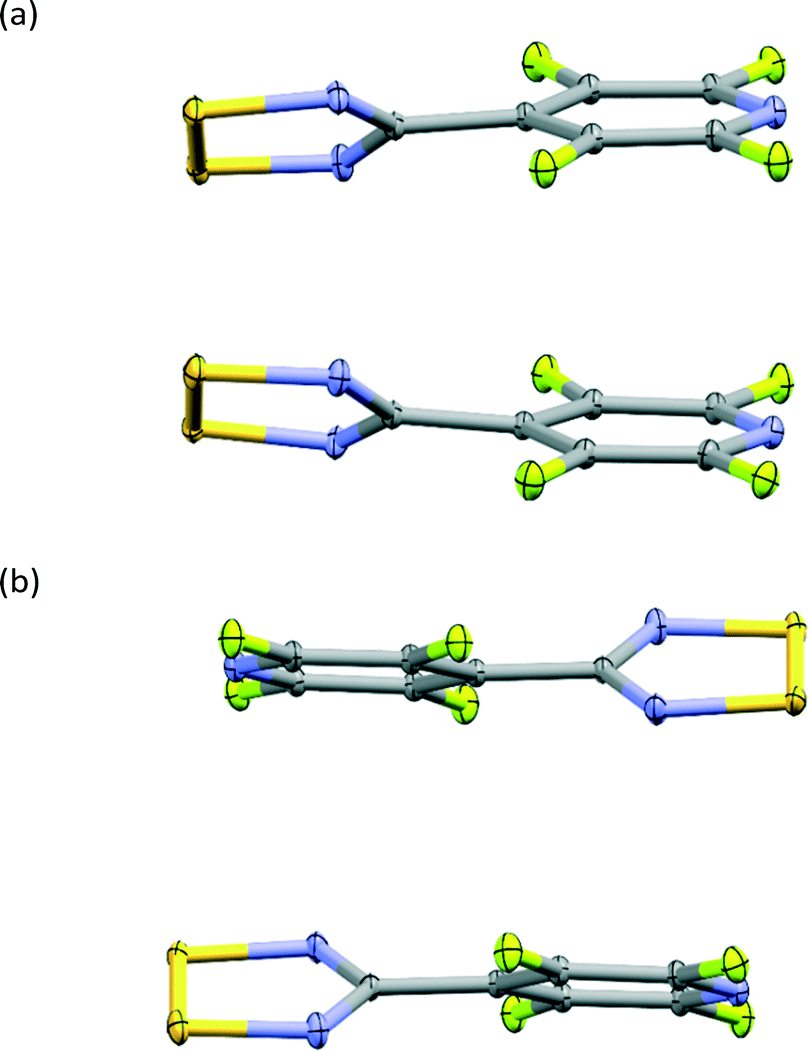 | ||
| Fig. 2 Dimeric structures in NF-radical with parallel (a) and antiparallel (b) packing. | ||
 | ||
| Fig. 3 An overlay of the packing in NF-radical (green) and F-radical (blue). | ||
The packing pattern has also been analysed using Hirshfeld surface analysis in Crystal Explorer54–56 in order to quantify the relative ratio of close contacts. The ratio values are shown in Fig. 4. In both cases the majority of contacts are of type S⋯X and F⋯X (X = F, N or C), close to 80%. It is notable that S⋯F contacts are more prevalent than S⋯N contacts in both cases. In the case of the NF-radical we have the perfluorophenyl ring, with the 5 fluorine atoms, replaced by the perfluoropyridyl ring. Therefore, one can expect a reduction in the number of contacts with fluorine atoms and an increase in contacts to nitrogen atoms. Indeed the S⋯F, F⋯F, F⋯C interactions are less numerous in the NF-radical, whereas the S⋯N and F⋯N interactions are more pronounced (Fig. 4). It is clear that these structures are dominated by electrostatic-type interactions.
 | ||
| Fig. 4 Relative contribution of the weak interactions [%] in the crystal lattice of (a) the NF-radical and (b) the F-radical using Hirshfeld surface analysis. | ||
Electron density investigations
 | ||
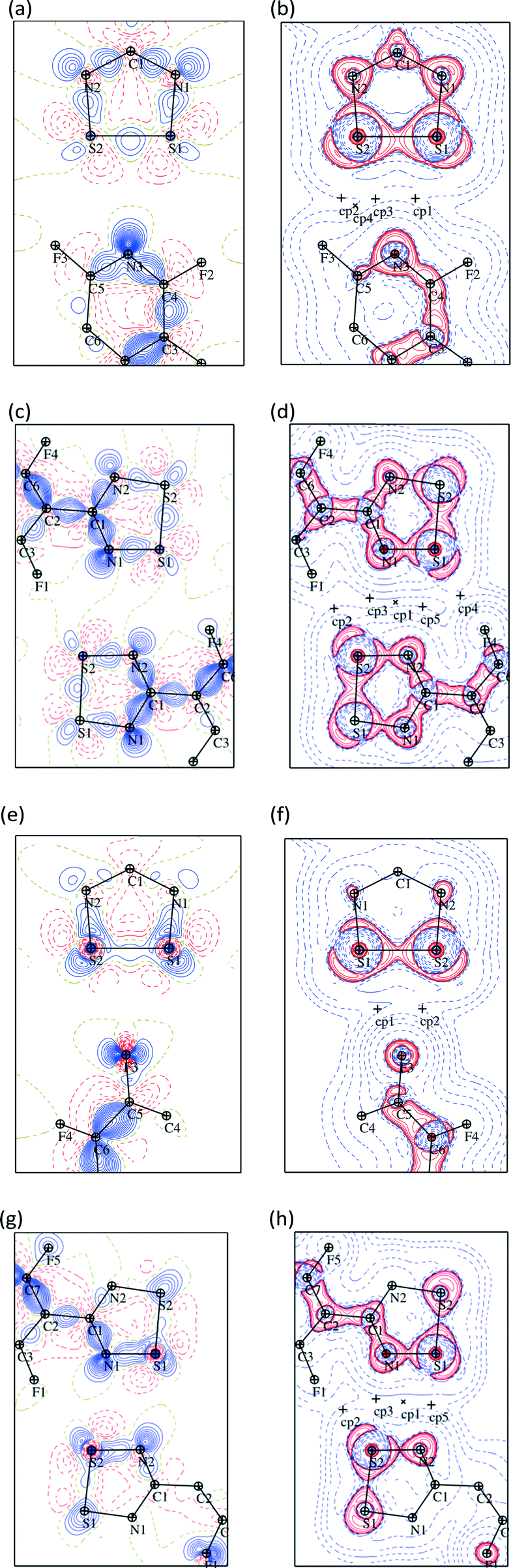
| Fig. 5 The BCPs of the NF-radical dimer (a, c) and the F-radical dimer (b, d) for the experimental models (a) and (b) and theoretical models (c) and (d), respectively. | ||
Some additional bond paths are also observed in the radical dimers, notably between carbon atoms and between F and N atoms, although the critical points have lower electron densities and Laplacians, more in line with those expected for non-covalent intermolecular interactions (Fig. 5 and Tables S3–S6†). In the case of the F-radical not all of the bond critical points (BCPs) were found in comparison to the previous model.22 This difference may be due to slightly different restraints and sigma cutoff used in the previous and current models. Particularly those BCPs with ρ(r) smaller than 0.05 e Å−3 are less likely to be detected in the current model. Similarly, some BCPs are missing in the experimental models compared to the theoretical models. Therefore, the existence of some BCPs, especially those with small values of ρ(r), may be dubious and strongly depends on the multipolar model used. Generally the position of BCPs and the value of the electron density at the BCPs for the weak interactions of radicals are well reproduced by the theoretical models. The BCPs for covalent interactions are also well reproduced by the theoretical models though the ρ(r) is systematically lower in the case of the theoretical model (Table S7†). The values of ρ(r) and ∇2ρ(r) for the NF-radical and the F-radical are in good agreement and very similar within the acceptable margin of 0.1–0.2 e Å−3 and 3 e Å−5 for the electron density and the Laplacian, respectively.57
Statistical analyses were performed on 3D grids of the deformation density around the NF-radical and F-radical molecules. The statistics are given in Table S8.† It is apparent that the deformation densities, both negative and positive, are slightly attenuated in the case of the experimental models when compared to the theoretical ones. The RMSD values between the experimental and the theoretical models are small: 0.016 e Å−3 and 0.021 e Å−3 for the NF-radical and F-radical, respectively. The correlation between the experimental and the theoretical deformation density is fair, though less satisfactory in the case of the F-radical. Fig. 6 shows the deformation and the Laplacian maps for the weak interactions between the dithiadiazolyl ring and the perfluorophenyl or perfluoropyridyl ring of the neighboring molecules. A complementary fit of the negative and positive densities for the two molecules is observed. This is even more clearly visible in the case of the Laplacian maps. The electron concentration region around atoms F3 or N3 is pointing towards the electron depletions in the vicinity of the sulfur atoms in the neighbouring molecule in both cases. A σ-hole on the fluorine atom is also clearly visible (Fig. 6e and f).58 Some additional maps that show interactions in dimers are presented in Fig. S3 and S4.†
 | ||
| Fig. 6 Deformation density and Laplacian maps for the NF-radical (a–d) and the F-radical (e–h) presenting S⋯N and S⋯F interactions. Maps are shown in the plane of the sulfur atoms from the first molecule and the N3 or F3 atom of the second molecule for the NF-radical and the F-radical, respectively. Blue solid lines denote the positive and red dashed lines denote the negative contours for the deformation maps. Contour level: ±0.05 e Å−3. In the case of the Laplacian maps the colors are inverse and the contours are drawn at ±2m × 10n e Å−5 (m = 1, 2, 3; n = −1, 0, 1, 2) levels. The ‘+’ signs denote the bond critical points. | ||
| Experimental/6-31G** | Optimized/6-31G** | Experimental/6-311++G** | ||||
|---|---|---|---|---|---|---|
| Dimer | Parallel | Antiparallel | Parallel | Antiparallel | Parallel | Antiparallel |
| a Previous paper.22 b Geometry taken from ref. 16. | ||||||
| NF-radical | −46.8 | −32.6 | −49.8 | −36.2 | −47.2 | −31.4 |
| F-radicala | −46.9 | −54.2 | −48.6 | |||
| HNF-radicalb | −46.8 | −28.2 | −54.2 | −31.2 | −50.8 | −29.3 |
| HF-radicala | −50.7 | −52.4 | −55.4 | |||
A relaxed potential energy surface scan with a step size of 5° was performed around the N1–C1–C2–C3 angle for the NF-radical to determine the rotational barrier for this molecule. The plot that shows the rotational barrier is presented in Fig. S5.† There are two maxima on the potential energy curve in the case of the NF-radical, one at 0° and a second at 90°, with the energy barriers close to 4 and 3 kJ mol−1, respectively. The height of the barriers and the overall shape of the PES plot is comparable to that of the F-radical. The most stable rotamer has a value of ∼45° for the N1–C1–C2–C3 angle. The angle values for the optimized structure agree quite well with the experimental values of ∼32(1)°. The double-minima observed in the PES plot are similar to those seen in other DTDAs fluorinated in both ortho positions,59 confirming that a wide range of twist angles between aryl and S–N rings are accessible within a small energy range.
The lattice energies for the NF-radical and the HNF-radical were calculated using periodic boundary conditions (Table 4). In the case of the lattice energy we observe reversed trends from those seen in dimerization energies: the highest lattice energy is observed for the NF-radical. It appears that the lattice energy for co-crystals is generally less negative than for the crystals based on the pure homo-components (Table 4).22
| NF-radical | −87.8 |
| HFN-radical | −79.4 |
Additionally, we computed the interaction energy based on the multipolar distribution for the NF-radical and F-radical for both experimental and theoretical models (Tables S10 and S11†). The strongest interactions are in co-facial parallel dimers as expected. However, in the case of the F-radical the experimental multipolar model for the facial dimer strongly underestimates the strength of this interaction (−26.4 kJ mol−1), both with respect to the theoretical model (−69.8 kJ mol−1) and when compared to similar interactions in the NF-radical, −76.3 and −61.4 kJ mol−1 for the experimental and the theoretical model, respectively. Due to this outlier the correlation between the theoretical and the experimental model is rather low (R = 0.729). If we omit this particular interaction the correlation coefficient increases to a satisfactory value of 0.943.
| NF-radical | F-radical | |||
|---|---|---|---|---|
| Exp. | Theo. | Exp. | Theo. | |
| Dithiadiazolyl-ring | 0.064 | 0.137 | 0.397 | 0.113 |
| 6-Membered ring | −0.059 | −0.134 | −0.390 | −0.108 |
| Total | 0.005 | 0.003 | 0.007 | 0.005 |
| RMSD | 0.113 | 0.141 | ||
| Corr. coeff. R | 0.987 | 0.975 | ||
 | ||
| Fig. 7 Electrostatic potential mapped on the Hirshfeld surface for the NF-radical (a, b) and the F-radical (c, d). The experimental model (a, c) and the model based on theoretical structure factors (b, d) are presented. The highest and lowest values of electrostatic potential are 0.1 and −0.1 e Å−1, respectively. | ||
These qualitative assessments have been followed by a detailed comparison of the electrostatic potential quantities43,44 calculated on 3D grids. The quantitative analysis of the electrostatic potential confirms the qualitative distribution. The RMSD values between experimental and theoretical models are rather low and equal to 0.037 e Å−1 and 0.045 e Å−1 for the NF-radical and F-radical, respectively. The overall correlation between experimental and theoretical models is fair as determined by the correlation coefficients. These are equal to 0.733 and 0.861 for the NF-radical and F-radical, respectively. The detailed statistics are given in Table S15.†
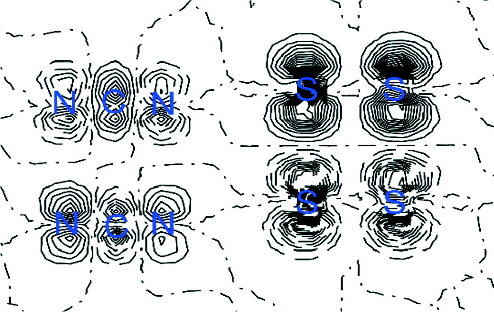 | ||
| Fig. 8 Spin density distribution map in the plane of the four sulfur atoms for the dimer of the NF-radical. The positive (solid line) and negative (dashed line) spin densities are shown. Contour level at ±0.001 au. | ||
Conclusions
An experimental charge density study was performed for the 4-perfluoropyridyl-1,2,3,5-dithiadiazolyl radical (NF-radical). The resulting analysis was compared to the previously reported analysis of the similar 4-perfluorophenyl-1,2,3,5-dithiadiazolyl (F-radical). Additional refinements based on the theoretical structure factors were performed for the reported radical as well as the previously analyzed 4-perfluorophenyl-1,2,3,5-dithiadiazolyl (F-radical).Both NF- and F-radicals form dimers in their crystal lattice. The strong interaction between sulfur atoms in the dimers is confirmed by the high values of electron density between these atoms: 0.166 e Å−3 and 0.149 e Å−3 for the NF-radical and F-radical, respectively. Analysis of the electron density makes it clear that these interactions are distinct from both covalent bonds and intermolecular interactions. Some additional bond paths are also observed in the dimers, most notably between carbon atoms and between F and N atoms. There are other interactions between radical molecules in the crystal lattice, although not as strong as those between sulfur atoms.
Analysis also revealed that spin density is almost entirely located on the nitrogen and sulfur atoms in the dithiadiazolyl ring for both radicals, in agreement with previous experimental measurements. However, the values of the spin density are higher in the case of the NF-radical, which may result in stronger interactions between sulfur atoms in dimers, which is supported by the electron density values at bond critical points. The dipole moments calculated for these radicals can be treated only qualitatively, but the integrated AIM charges and electrostatic potentials correlate well with the theoretical models.
Acknowledgements
SD thanks the Polish National Science Centre for the financial support within the OPUS programme (Grant No. UMO-2012/05/B/ST4/03339). Quantum calculations were carried out in the Wrocław Centre for Networking and Supercomputing (http://www.wcss.pl) (Grant No. 115). The study was carried out at the Biological and Chemical Research Centre, University of Warsaw, established within the project cofinanced by the European Union from the European Regional Development Fund under the Operational Programme Innovative Economy, 2007−2013. DAH thanks the National Research Foundation‡ and Stellenbosch University for funding.Notes and references
- J. M. Rawson, A. Alberola and A. Whalley, J. Mater. Chem., 2006, 16, 2560–2575 RSC.
- A. J. Banister, N. Bricklebank, W. Clegg, M. R. J. Elsegood, C. I. Gregory, I. Lavender, J. M. Rawson and B. K. Tanner, J. Chem. Soc., Chem. Commun., 1995, 679–680 RSC.
- A. Alberola, R. J. Less, C. M. Pask, J. M. Rawson, F. Palacio, P. Oliete, C. Paulsen, A. Yamaguchi, R. D. Farley and D. M. Murphy, Angew. Chem., Int. Ed., 2003, 42, 4782–4785 CrossRef CAS PubMed.
- G. Antorrena, F. Palacio, J. E. Davies, M. Hartley, J. M. Rawson, J. N. N. B. Smith and A. Steiner, Chem. Commun., 1999, 1393–1394 RSC.
- A. Alberola, R. J. R. J. Less, F. Palacio, C. M. C. M. Pask and J. M. J. M. Rawson, Molecules, 2004, 9, 771–781 CrossRef CAS PubMed.
- A. Alberola, C. S. Clarke, D. A. Haynes, S. I. Pascu and J. M. Rawson, Chem. Commun., 2005, 4726–4728 RSC.
- D. A. Haynes, CrystEngComm, 2011, 13, 4793–4805 RSC.
- J. M. Rawson, A. J. Banister and I. Lavender, Adv. Heterocycl. Chem., 1995, 62, 137–247 CrossRef CAS.
- A. Vegas, A. Pérez-Salazar, A. J. Banister and R. G. Hey, J. Chem. Soc., Dalton Trans., 1980, 1812–1815 RSC.
- A. W. Cordes, C. D. Bryan, W. M. Davis, R. H. de Laat, S. H. Glarum, J. D. Goddard, R. C. Haddon, R. G. Hicks, D. K. Kennepohl, R. T. Oakley, S. R. Scott and N. P. C. Westwood, J. Am. Chem. Soc., 1993, 115, 7232–7239 CrossRef CAS.
- H. Z. Beneberu, Y.-H. Tian and M. Kertesz, Phys. Chem. Chem. Phys., 2012, 14, 10713–10725 RSC.
- K. E. Preuss, Polyhedron, 2014, 79, 1–15 CrossRef CAS.
- Z. Cui, H. Lischka, H. Z. Beneberu and M. Kertesz, J. Am. Chem. Soc., 2014, 136, 12958–12965 CrossRef CAS PubMed.
- A. Alberola, E. Carter, C. P. Constantinides, D. J. Eisler, D. M. Murphy and J. M. Rawson, Chem. Commun., 2011, 47, 2532–2534 RSC.
- C. Allen, D. A. Haynes, C. M. Pask and J. M. Rawson, CrystEngComm, 2009, 11, 2048–2050 RSC.
- S. W. Robinson, D. A. Haynes and J. M. Rawson, CrystEngComm, 2013, 15, 10205–10211 RSC.
- Bruker, APEXII, SAINT and SADABS, Bruker AXS Inc., Madison, Wisconsin, USA, 2012 Search PubMed.
- R. H. Blessing, J. Appl. Crystallogr., 1989, 22, 396–397 CrossRef.
- R. H. Blessing, Acta Crystallogr., Sect. A: Found. Crystallogr., 1995, 51, 33–38 CrossRef.
- G. M. Sheldrick, Acta Crystallogr., Sect. A: Found. Crystallogr., 2008, 64, 112–122 CrossRef CAS PubMed.
- O. V. Dolomanov, L. J. Bourhis, R. J. Gildea, J. A. K. Howard and H. Puschmann, J. Appl. Crystallogr., 2009, 42, 339–341 CrossRef CAS.
- S. Domagała, K. Kosc, S. W. Robinson, D. A. Haynes and K. Woźniak, Cryst. Growth Des., 2014, 14, 4834–4848 Search PubMed.
- M. J. Frisch, G. W. Trucks, H. B. Schlegel, G. E. Scuseria, M. A. Robb, J. R. Cheeseman, G. Scalmani, V. Barone, B. Mennucci, G. A. Petersson, H. Nakatsuji, M. Caricato, X. Li, H. P. Hratchian, A. F. Izmaylov, J. Bloino, G. Zheng, J. L. Sonnenberg, M. Hada, M. Ehara, K. Toyota, R. Fukuda, J. Hasegawa, M. Ishida, T. Nakajima, Y. Honda, O. Kitao, H. Nakai, T. Vreven, J. J. A. Montgomery, J. E. Peralta, F. Ogliaro, M. Bearpark, J. J. Heyd, E. Brothers, K. N. Kudin, V. N. Staroverov, T. Keith, R. Kobayashi, J. Normand, K. Raghavachari, A. Rendell, J. C. Burant, S. S. Iyengar, J. Tomasi, M. Cossi, N. Rega, J. M. Millam, M. Klene, J. E. Knox, J. B. Cross, V. Bakken, C. Adamo, J. Jaramillo, R. Gomperts, R. E. Stratmann, O. Yazyev, A. J. Austin, R. Cammi, C. Pomelli, J. W. Ochterski, R. L. Martin, K. Morokuma, V. G. Zakrzewski, G. A. Voth, P. Salvador, J. J. Dannenberg, S. Dapprich, A. D. Daniels, O. Farkas, J. B. Foresman, J. V. Ortiz, J. Cioslowski and D. J. Fox, Gaussian 09, Revision B.01, Gaussian Inc., Wallingford CT, 2009 Search PubMed.
- R. Dovesi, R. Orlando, B. Civalleri, C. Roetti, V. R. Saunders and C. M. Zicovich-Wilson, Z. Kristallogr., 2005, 220, 571–573 CAS.
- R. Dovesi, V. R. Saunders, C. Roetti, R. Orlando, C. M. Zicovich-Wilson, F. Pascale, B. Civalleri, K. Doll, N. M. Harrison, I. J. Bush, P. D'Arco and M. Llunell, CRYSTAL09 User's Manual, University of Turin, Turin, Italy, 2009 Search PubMed.
- F. H. Allen, Acta Crystallogr., Sect. B: Struct. Sci., 2002, 58, 380–388 CrossRef.
- F. H. Allen and I. J. Bruno, Acta Crystallogr., Sect. B: Struct. Sci., 2010, 66, 380–386 CrossRef CAS PubMed.
- R. Kamiński, K. N. Jarzembska and S. Domagała, J. Appl. Crystallogr., 2013, 46, 540–543 CrossRef.
- S. Grimme, J. Comput. Chem., 2006, 27, 1787–1799 CrossRef CAS PubMed.
- C. Lee, W. Yang and R. G. Parr, Phys. Rev. B: Condens. Matter Mater. Phys., 1988, 37, 785–789 CrossRef CAS.
- A. D. Becke, J. Chem. Phys., 1993, 98, 5648–5652 CrossRef CAS.
- P. C. Hariharan and J. A. Pople, Theor. Chim. Acta, 1973, 28, 213–222 CrossRef CAS.
- B. Civalleri, C. M. Zicovich-Wilson, L. Valenzano and P. Ugliengo, CrystEngComm, 2008, 10, 1–6 RSC.
- M. A. Spackman, Chem. Rev., 1992, 92, 1769–1797 CrossRef CAS.
- P. Coppens, X-Ray Charge Densities and Chemical Bonding, Oxford University Press, Inc., New York, 1997 Search PubMed.
- B. Guillot, L. Viry, R. Guillot, C. Lecomte and C. Jelsch, J. Appl. Crystallogr., 2001, 34, 214–223 CrossRef CAS.
- C. Jelsch, B. Guillot, A. Lagoutte and C. Lecomte, J. Appl. Crystallogr., 2005, 38, 38–54 Search PubMed.
- R. Bader, Atoms in Molecules: A Quantum Theory, Clarendon Press; Oxford University Press, Oxford [England]: New York, 1994 Search PubMed.
- A. Stash and V. Tsirelson, J. Appl. Crystallogr., 2002, 35, 371–373 CrossRef CAS.
- A. D. Becke, J. Chem. Phys., 1988, 88, 2547–2553 CrossRef CAS.
- V. I. Lebedev and D. N. Laikov, Dokl. Math., 1999, 59, 477–481 Search PubMed.
- O. Treutler and R. Ahlrichs, J. Chem. Phys., 1995, 102, 346–354 CrossRef CAS.
- J. S. Murray and P. Politzer, J. Mol. Struct.: THEOCHEM, 1998, 425, 107–114 CrossRef CAS.
- J. S. Murray, Z. Peralta-Inga and P. Politzer, Int. J. Quantum Chem., 2000, 80, 1216–1223 CrossRef CAS.
- F. L. Hirshfeld, Acta Crystallogr., Sect. B: Struct. Crystallogr. Cryst. Chem., 1971, 27, 769–781 CrossRef CAS.
- M. A. Spackman, J. J. McKinnon and D. Jayatilaka, CrystEngComm, 2008, 10, 377–388 CAS.
- B. Guillot, E. Enrique, L. Huder and C. Jelsch, Acta Crystallogr., Sect. A: Found. Adv., 2014, 70, C279–C279 Search PubMed.
- N. K. Hansen and P. Coppens, Acta Crystallogr., Sect. A: Cryst. Phys., Diffr., Theor. Gen. Crystallogr., 1978, 34, 909–921 CrossRef.
- K. Meindl and J. Henn, Acta Crystallogr., Sect. A: Found. Crystallogr., 2008, 64, 404–418 CrossRef CAS PubMed.
- Y. Le Page and E. J. Gabe, J. Appl. Crystallogr., 1979, 12, 464–466 CrossRef CAS.
- H. D. Flack, J. Appl. Crystallogr., 1984, 17, 361–362 CrossRef CAS.
- C. F. Macrae, P. R. Edgington, P. McCabe, E. Pidcock, G. P. Shields, R. Taylor, M. Towler and J. van de Streek, J. Appl. Crystallogr., 2006, 39, 453–457 CrossRef CAS.
- C. F. Macrae, I. J. Bruno, J. A. Chisholm, P. R. Edgington, P. McCabe, E. Pidcock, L. Rodriguez-Monge, R. Taylor, J. van de Streek and P. A. Wood, J. Appl. Crystallogr., 2008, 41, 466–470 CrossRef CAS.
- M. A. Spackman and J. J. McKinnon, CrystEngComm, 2002, 4, 378–392 RSC.
- J. J. McKinnon, M. A. Spackman and A. S. Mitchell, Acta Crystallogr., Sect. B: Struct. Sci., 2004, 60, 627–668 CrossRef PubMed.
- J. J. McKinnon, D. Jayatilaka and M. A. Spackman, Chem. Commun., 2007, 3814–3816 RSC.
- R. Kamiński, S. Domagała, K. N. Jarzembska, A. A. Hoser, W. F. Sanjuan-Szklarz, M. J. Gutmann, A. Makal, M. Malińska, J. M. B
![[a with combining cedilla]](https://www.rsc.org/images/entities/char_0061_0327.gif) k and K. Woźniak, Acta Crystallogr., Sect. A: Found. Adv., 2014, 70, 72–91 Search PubMed.
k and K. Woźniak, Acta Crystallogr., Sect. A: Found. Adv., 2014, 70, 72–91 Search PubMed. - P. Politzer and J. S. Murray, ChemPhysChem, 2013, 14, 278–294 CrossRef CAS PubMed.
- C. S. Clarke, D. A. Haynes, J. N. B. Smith, A. S. Batsanov, J. A. K. Howard, S. I. Pascu and J. M. Rawson, CrystEngComm, 2010, 12, 172–185 RSC.
- M. A. Spackman, P. Munshi and B. Dittrich, ChemPhysChem, 2007, 8, 2051–2063 CrossRef CAS PubMed.
- F. L. Lee, K. F. Preston, A. J. Williams, L. H. Sutcliffe, A. J. Banister and S. T. Wait, Magn. Reson. Chem., 1989, 27, 1161–1165 CrossRef CAS.
- J. M. Rawson, C. S. Clarke and D. W. Bruce, Magn. Reson. Chem., 2009, 47, 3–8 CrossRef CAS PubMed.
- Y. Beldjoudi, D. A. Haynes, J. J. Hayward, W. J. Manning, D. R. Pratt and J. M. Rawson, CrystEngComm, 2013, 15, 1107–1113 RSC.
Footnotes |
| † Electronic supplementary information (ESI) available: Tables with refined parameters, bond critical point properties, deformation density and electrostatic potential statistics, electrostatic interaction energies, dipole moments, AIM charges, atomic spins. Figures with residual and fractal residual densities, deformation density and Laplacian maps and relaxed potential energy scan. X-ray crystallographic data have been deposited with the Cambridge Structural Database: CCDC numbers: 1049767 and 1479036 for the F-radical and NF-radical, respectively. For ESI and crystallographic data in CIF or other electronic format see DOI: 10.1039/c6ce01095d |
| ‡ This material is based upon work supported financially by the National Research Foundation of South Africa. Any opinion, findings and conclusions or recommendations expressed in this material are those of the authors and therefore the NRF does not accept any liability in regard thereto. |
| This journal is © The Royal Society of Chemistry 2016 |