 Open Access Article
Creative Commons Attribution 3.0 Unported Licence
Control of interpenetration of copper-based MOFs on supported surfaces by electrochemical synthesis†
Sumit
Sachdeva
ab,
Alexey
Pustovarenko
b,
Ernst J. R.
Sudhölter
a,
Freek
Kapteijn
b,
Louis C. P. M.
de Smet
a and
Jorge
Gascon
*b
aOrganic Materials and Interfaces, Department of Chemical Engineering, Delft University of Technology, Delft, The Netherlands
bCatalysis Engineering, Department of Chemical Engineering, Delft University of Technology, Delft, The Netherlands. E-mail: j.gascon@tudelft.nl
First published on 11th January 2016
Abstract
A study of a copper-based metal–organic framework (MOF) synthesized by an electrochemical route is presented. Morphological and adsorption properties of the MOF synthesized as bulk powder and on supported copper surfaces were investigated. Differences in these properties and structural refinement studies indicate that when 4,4′,4′′-s-triazine-2,4,6-triyl-tribenzoic acid (H3TATB) is used as linker interpenetration can be prevented when the structure is grown on a surface.
Metal–organic frameworks (MOFs) are porous, crystalline materials comprised of metal ions coordinatively linked with organic ligands.1–3 The high porosity and structural versatility of these materials have attracted research towards many potential applications, including gas separation,4 gas storage,5 drug delivery,6 catalysis7 and sensing.8 Some of these applications require MOFs to be grown as thin films9 with a maximum pore volume available for selective gas interactions.
Another interesting aspect about MOF chemistry lays in the principle of isoreticular design, which was introduced by Yaghi.10 Typically, the first step within this concept involves figuring out the reaction conditions that lead to the formation of a particular tecton with corresponding connectivity. Then control over the formation of similar MOFs becomes possible by simply changing the size of the organic linker while keeping the same connectivity.11 This can further allow systematic control over pore size and functionality of MOFs. Such a powerful approach has however a number of limitations, the most important being the fact that the use of longer organic linkers may lead to network interpenetration, with the corresponding loss in porosity.2,12,13
In spite of the importance of interpenetration for the final application opportunities of MOFs, only a few studies have been reported on the control of this phenomenon.13 The general approach in most cases relies on changing reaction conditions,14 solvent removal15 or by using a template,16 while, to the best of our knowledge, only one study deals with the control of interpenetration during surface growth.17 In this case, interpenetration is suppressed by using liquid-phase epitaxy on an organic template, resulting in a controlled layer-by-layer growth preventing interpenetration.
Over the last few decades, several approaches have been developed for the positioning of MOFs on different surfaces.18 Pioneered by BASF for the continuous production of MOF crystals,19 electrochemical synthesis allows the metal salt-free synthesis of MOFs. The principle relies on supplying the metal ion by anodic dissolution to a synthesis solution of the organic linker in an electrolyte. The production of MOF coatings on electrodes is another attractive feature of electrochemistry.20–23 In previous years we, among others, have demonstrated that it is possible to synthesize high-quality coatings of MOF structures such as HKUST-1 on the surface of Cu electrodes. In short, the high concentration of Cu ions near the surface of the electrode upon application of voltage favours formation of the MOF on the electrode. Recently, we optimized the process in terms of MOF growth over the electrode surface by using a pulsed current for a limited number of cycles.20
Building on our previous works on electrochemical synthesis of Cu-based MOFs, we report a simple, fast and controlled way of limiting framework interpenetration in a framework isoreticular with the well-known HKUST-1. In order to investigate the interpenetration process, we performed the electrochemical synthesis of Cu paddlewheel MOFs using benzene-1,3,5-tricarboxylic acid (H3BTC) and 4,4′,4′′-s-triazine-2,4,6-triyl-tribenzoic acid (H3TATB) as organic linkers (Fig. S1†). The MOFs were synthesized under optimized synthesis conditions by an electrochemical route. Hereafter, these MOFs will be referred as CuBTC and CuTATB respectively. CuBTC is a well-characterized MOF24 and it has been chosen as reference material as there should be no interpenetration due to the small size of the linker.
The syntheses of CuBTC and CuTATB were carried out in an electrochemical cell in a 96% ethanol solution. Conditions were tuned in such a way that all of these MOFs could be synthesized both as bulk powder and as surface-supported films on copper electrodes (see ESI† for experimental details). After synthesis, these materials were filtered and washed with ethanol to remove the excess unreacted linker and electrolyte before being dried at 100 °C. In a second step, the electrolyte concentration and the number of current cycles were modified to obtain uniform, crack-free layers on the surface.
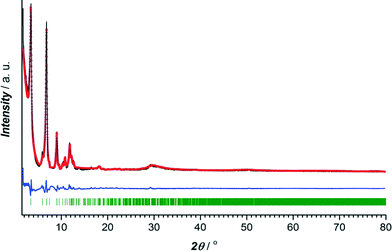
The crystalline nature of CuBTC and CuTATB was determined by powder X-ray diffraction with cobalt as X-ray source. The diffraction pattern of synthesized CuBTC was similar to patterns simulated from the crystal structure and as reported from the literature20 (Fig. S2†). Known MOF structures built of copper metal centres and H3TATB as a linker did not show resemblance with the synthesized CuTATB,25,26 but resembled a highly interpenetrated polymeric structure based on copper and 4,4′,4′′,-benzene-1,3,5-triyl-tris(benzoic acid) (H3BTB), reported by Walton et al.27 Furthermore, based on this known CuBTB structure, the isostructurality of CuTATB was confirmed by Rietveld refinement showing only slight differences in the unit cell dimensions (Fig. 1, Table S1†).
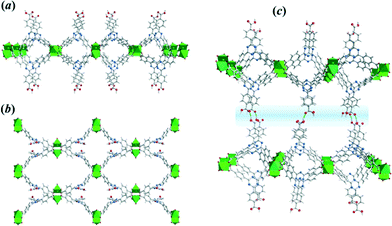
Thus, the CuTATB framework consists of a 2D polymeric network built from copper paddlewheel units, linked in an alternated manner by the two carboxylate groups of the TATB ligand (Fig. 2). One of them is protonated and points out of the 2D polymeric layer, being involved in hydrogen bonding with the parallel-laid network, forming a 3D architecture (Fig. 2c). By using simplified building units for this 3D structure (as illustrated in Fig. S4†) shows that the network can be described as a 3,4-connected binodal net of sur topological type and expressed by a (62·82·102)(62·8)2 Schläfli symbol.28 Furthermore, the network structure of CuTATB consists of four highly interpenetrated simple nets where each net is symmetry-equivalent and related to other by translations [100] and by inversion (Fig. S5†). All the interpenetration nets have the topology of sur net and the interpenetration type belongs to a rare class IIIa (for details see ESI†).29
MOF films were synthesized on copper electrode surfaces including copper meshes. Powder XRD patterns for CuTATB coated electrodes exhibits a single detectable peak at 2θ = 6.42° that does not match with the sample obtained in bulk (Fig. S6†). Additionally, similar patterns were obtained even when the synthesis was carried out with higher number of cycles. It was observed that during the electrochemical synthesis of CuTATB, a thin layer of MOF was formed on the copper mesh in the first seconds of the synthesis. This further resulted in the formation of islands at various nucleation sites as reported recently.30 As the intergrowth of the deposited MOF layer takes place, these islands can detach from the surface. This detachment can also have self-limiting effect on thickness of the deposited layer. Thus, these processes result in layers of similar thickness of MOFs even when the synthesis was carried out with higher number of cycles (up to 200 cycles). In order to identify the structure of the MOF directly grown on the Cu surface, this surface was scratched off and analysed by XRD (Fig. S6†). A comparison of experimental XRD patterns with simulated ones for CuBTC and CuTATB (here compared to the previously reported PCN-6 MOF)25 was performed. The reflection at 2θ = 6.42° corresponds well with the most intense (202) diffraction of the PCN-6 structure (Fig. S6†). Correspondingly, the crystal structure of CuTATB consists of a 3D network of the cage-type architecture and possesses large accessible voids (Fig. 3a and b).
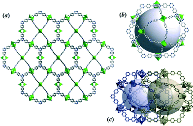 | ||
| Fig. 3 (a) The 3D framework structure of CuTATB MOF grown on the electrode surface, (b) visualization of the cage of non-interpenetrated CuTATB MOF (PCN-6′), and (c) arrangement of voids within the interpenetrated structure of PCN-6. All structures were obtained based on reported studies.25,26 | ||
However, compared to the non-interpenetrated (PCN-6′) framework, the free accessible volumes of the cages of the low-interpenetrated form of the PCN-6 structure reduces by a factor of about 1.5,26 as a result of the interpenetration of two equivalent frameworks (Fig. 3c). Following a previously used consideration for the bulk framework simplification (Fig. S4a and b†), the network of CuTATB grown on the electrode surface (PCN-6) is a 3,4-connected binodal net of twisted boracite topological type (tbo) and expressed by a (62·82·102)3(63)4 Schläfli symbol.28 Moreover, the network structure consists of two equivalent symmetry nets, which are interpenetrated29(Fig. S7†).
Further characterization of these materials was carried out using scanning electron microscopy (SEM). Synthesized powder samples of CuTATB with constant current synthesis showed needle-like structures (Fig. 4a and b). The obtained material also showed a wide particle size distribution where the length varied from nanometres to a few micrometres. When the material was synthesized on the supported surfaces, a different morphology of the material was observed. By using a square-wave electrical current for the electrochemical growth of copper-based MOFs, concentration polarization near the surface of the metal electrode can be controlled. This leads to a good MOF coverage on the electrode surface (Fig. 4c) due to a fast nucleation process.
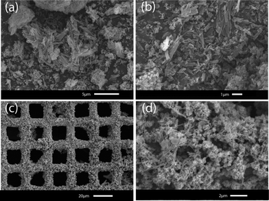 | ||
| Fig. 4 Scanning electron microscope pictures of CuTATB synthesized as bulk powder (a and b), and grown on a copper mesh (c and d). | ||
To further investigate the differences in the bulk powder MOFs and MOFs grown on surface in terms of porosity, gas adsorption studies were performed. The reference CuBTC MOF displayed a similar isotherm and BET surface area (~1300 m2 g−1) as reported in the literature16 (Fig. S9†). Fig. 5a and b shows the N2 adsorption isotherms at 77 K of CuTATB measured as bulk powder and as a deposited layer on several copper meshes. The isotherm indicates a microporous nature of CuTATB (Fig. 5a). The BET area and Langmuir area of CuTATB, calculated from N2 adsorption isotherm, were found to be approximately 570 m2 g−1 and 740 m2 g−1, respectively. The porosity of the material was also observed to be close to the reported material with H3BTB synthesized solvothermally.27 Further, in case of CuTATB, the amount of N2 adsorbed per mol of copper in the MOF was similar to that of CuBTC (Fig. S9†).
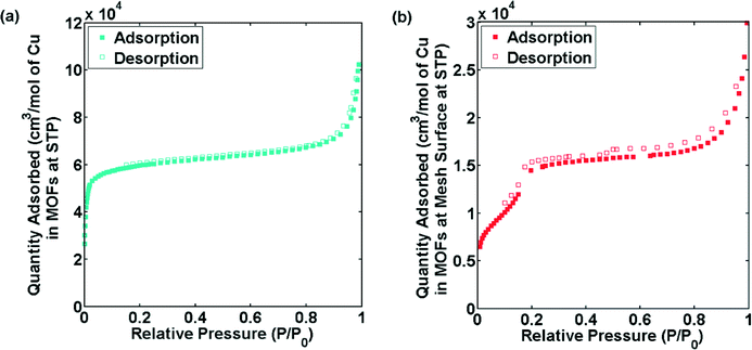 | ||
| Fig. 5 N2 sorption isotherms of CuTATB, synthesized as bulk powder (a) and obtained from multiple electrochemically modified copper meshes (b). | ||
In contrast, the N2 adsorption isotherm of CuTATB deposited on a copper mesh shows a completely different shape (Fig. 5b). Even though the exact mass of the deposited material could not be calculated (although roughly estimated by measuring the mass change of electrode), the N2 adsorption isotherm shows a two-step shape (Fig. 5b), indicating a clear difference in the structure of CuTATB synthesized on the surface. This is also supported by the XRD pattern of the MOF on the mesh as discussed earlier (Fig. S6†). Further, the cage structure in the molecular network, which arises from controlling interpenetration in the structure, supports the two-step adsorption.
The results obtained so far indicate that there are differences in properties of CuTATB on surface growth with respect to the powder samples. This can be attributed to interpenetration in these large linkers in powder form. The interpenetration in these samples can be rationalized by the following. In order to minimize the energy in the larger networks in these MOFs due to bulky linkers (i.e. H3TATB), the free void space in the material is filled by the units of the framework, which can lead to interpenetration.13 This interpenetration also affects the sorption behaviour.15 A similar two-step behaviour for N2 adsorption as shown in Fig. 4 for CuTATB has been reported earlier for other materials as well on the control of interpenetration in the framework.15,31 Moreover, other MOFs based on copper metal and H3TATB or H3BTB as similar organic linker have also shown interpenetration, resulting in materials like PCN-6 (ref. 25, 26) and MOF-14 (ref. 10) respectively. Non-interpenetrated alternatives of PCN-6 and MOF-14, PCN-6′ (ref. 16, 26) and MOF-143 (ref. 32) were also synthesized by modification of synthesis conditions. It should be noted that the electrochemically synthesized powder MOF did not show any resemblance with these MOFs. That can be attributed to a reduced solubility of the linkers in ethanol. In order to increase the solubility, the synthesis process was also carried out at 70 °C. It resulted in the formation of MOFs with similar properties as the RT-prepared MOFs.
During the electrochemical synthesis, the generation of a high density of metal ions allows the formation of small crystals that end up in the solution. With the use of a pulsed current, the generation of these copper ions is controlled, which results in the growth of MOF on the surface, as the fast nucleation rate of copper MOFs allows crystallization taking place on the electrode surface layer. Further, molecular reorientation of organic ligands near the copper surface can modify the morphological and structural characteristics of the formed MOF.33,34 The controlled generation of copper ions, molecular reorientation of organic ligands near copper surface and hence the growth kinetics by electrochemical synthesis can affect the interpenetration in the formed MOFs.
Conclusions
Copper-based metal–organic frameworks (MOFs) were prepared by electrochemical synthesis using an elongated linker with similar geometry to that of benzene 1,3,5-tricarboxylic acid (H3BTC). Our results demonstrate clear differences in the properties of the MOF grown in the bulk and the MOF grown on the surface of the electrodes. These differences can be attributed to the observation that growth on the surface prevents the interpenetration of the MOF network.Acknowledgements
This work was supported by NanoNextNL, a micro and nanotechnology consortium of the Government of the Netherlands and 130 partners. The authors acknowledge the financial support of the European Research Council under the European Union's Seventh Framework Programme (FP/2007-2013), ERC Grant Agreement no. 335746, CrystEng-MOF-MMM. We also thank Duco Bosma, Willy Rook and Deepak Pratap Singh for technical assistance.References
- M. D. Allendorf and V. Stavila, CrystEngComm, 2015, 17, 229–246 RSC.
- H. Furukawa, K. E. Cordova, M. O'Keeffe and O. M. Yaghi, Science, 2013, 341 Search PubMed.
- S. L. James, Chem. Soc. Rev., 2003, 32, 276–288 RSC.
- T. Rodenas, I. Luz, G. Prieto, B. Seoane, H. Miro, A. Corma, F. Kapteijn, F. X. Llabrés i Xamena and J. Gascon, Nat. Mater., 2015, 14, 48–55 CrossRef CAS PubMed.
- L. J. Murray, M. Dinca and J. R. Long, Chem. Soc. Rev., 2009, 38, 1294–1314 RSC.
- P. Horcajada, T. Chalati, C. Serre, B. Gillet, C. Sebrie, T. Baati, J. F. Eubank, D. Heurtaux, P. Clayette, C. Kreuz, J.-S. Chang, Y. K. Hwang, V. Marsaud, P.-N. Bories, L. Cynober, S. Gil, G. Ferey, P. Couvreur and R. Gref, Nat. Mater., 2010, 9, 172–178 CrossRef CAS PubMed.
- J. Gascon, A. Corma, F. Kapteijn and F. X. Llabrés i Xamena, ACS Catal., 2013, 4, 361–378 CrossRef.
- L. E. Kreno, K. Leong, O. K. Farha, M. Allendorf, R. P. Van Duyne and J. T. Hupp, Chem. Rev., 2011, 112, 1105–1125 CrossRef PubMed.
- A. Bétard and R. A. Fischer, Chem. Rev., 2011, 112, 1055–1083 CrossRef PubMed.
- B. Chen, M. Eddaoudi, S. T. Hyde, M. O'Keeffe and O. M. Yaghi, Science, 2001, 291, 1021–1023 CrossRef CAS PubMed.
- M. G. Goesten, F. Kapteijn and J. Gascon, CrystEngComm, 2013, 15, 9249–9257 RSC.
- O. M. Yaghi, Nat. Mater., 2007, 6, 92–93 CrossRef CAS PubMed.
- H.-L. Jiang, T. A. Makal and H.-C. Zhou, Coord. Chem. Rev., 2013, 257, 2232–2249 CrossRef CAS.
- J. Zhang, L. Wojtas, R. W. Larsen, M. Eddaoudi and M. J. Zaworotko, J. Am. Chem. Soc., 2009, 131, 17040–17041 CrossRef CAS PubMed.
- S. B. Choi, H. Furukawa, H. J. Nam, D.-Y. Jung, Y. H. Jhon, A. Walton, D. Book, M. O'Keeffe, O. M. Yaghi and J. Kim, Angew. Chem., Int. Ed., 2012, 51, 8791–8795 CrossRef CAS PubMed.
- S. Ma, D. Sun, M. Ambrogio, J. A. Fillinger, S. Parkin and H.-C. Zhou, J. Am. Chem. Soc., 2007, 129, 1858–1859 CrossRef CAS PubMed.
- O. Shekhah, H. Wang, M. Paradinas, C. Ocal, B. Schupbach, A. Terfort, D. Zacher, R. A. Fischer and C. Woll, Nat. Mater., 2009, 8, 481–484 CrossRef CAS PubMed.
- P. Falcaro, R. Ricco, C. M. Doherty, K. Liang, A. J. Hill and M. J. Styles, Chem. Soc. Rev., 2014, 43, 5513–5560 RSC.
- U. Mueller, M. Schubert, F. Teich, H. Puetter, K. Schierle-Arndt and J. Pastre, J. Mater. Chem., 2006, 16, 626–636 RSC.
- A. M. Joaristi, J. Juan-Alcaniz, P. Serra-Crespo, F. Kapteijn and J. Gascon, Cryst. Growth Des., 2012, 12, 3489–3498 Search PubMed.
- U. Mueller, H. Puetter, M. Hesse, M. Schubert, H. Wessel, J. Huff and M. Guzmann, U.S. Pat. No. 8163949, 2012 Search PubMed.
- R. Ameloot, L. Stappers, J. Fransaer, L. Alaerts, B. F. Sels and D. E. De Vos, Chem. Mater., 2009, 21, 2580–2582 CrossRef CAS.
- I. Stassen, M. Styles, T. Van Assche, N. Campagnol, J. Fransaer, J. Denayer, J.-C. Tan, P. Falcaro, D. De Vos and R. Ameloot, Chem. Mater., 2015, 27, 1801–1807 CrossRef CAS.
- S. S.-Y. Chui, S. M.-F. Lo, J. P. H. Charmant, A. G. Orpen and I. D. Williams, Science, 1999, 283, 1148–1150 CrossRef CAS PubMed.
- D. Sun, S. Ma, Y. Ke, D. J. Collins and H.-C. Zhou, J. Am. Chem. Soc., 2006, 128, 3896–3897 CrossRef CAS PubMed.
- J. Kim, S.-T. Yang, S. B. Choi, J. Sim, J. Kim and W.-S. Ahn, J. Mater. Chem., 2011, 21, 3070–3076 RSC.
- B. Mu, F. Li and K. S. Walton, Chem. Commun., 2009, 2493–2495 RSC.
- V. A. Blatov, A. P. Shevchenko and D. M. Proserpio, Cryst. Growth Des., 2014, 14, 3576–3586 CAS.
- I. A. Baburin, V. A. Blatov, L. Carlucci, G. Ciani and D. M. Proserpio, J. Solid State Chem., 2005, 178, 2452–2474 CrossRef CAS.
- N. Campagnol, T. Van Assche, L. Stappers, J. F. M. Denayer, K. Binnemans, D. E. De Vos and J. Fransaer, ECS Trans., 2014, 61, 25–40 CrossRef.
- S. Bureekaew, H. Sato, R. Matsuda, Y. Kubota, R. Hirose, J. Kim, K. Kato, M. Takata and S. Kitagawa, Angew. Chem., Int. Ed., 2010, 49, 7660–7664 CrossRef CAS PubMed.
- H. Furukawa, Y. B. Go, N. Ko, Y. K. Park, F. J. Uribe-Romo, J. Kim, M. O'Keeffe and O. M. Yaghi, Inorg. Chem., 2011, 50, 9147–9152 CrossRef CAS PubMed.
- J. V. Barth, J. Weckesser, N. Lin, A. Dmitriev and K. Kern, Appl. Phys. A: Mater. Sci. Process., 2003, 76, 645–652 CrossRef CAS.
- S. Stepanow, T. Strunskus, M. Lingenfelder, A. Dmitriev, H. Spillmann, N. Lin, J. V. Barth, C. Wöll and K. Kern, J. Phys. Chem. B, 2004, 108, 19392–19397 CrossRef CAS.
Footnote |
| † Electronic supplementary information (ESI) available. See DOI: 10.1039/c5ce02462e |
| This journal is © The Royal Society of Chemistry 2016 |

