 Open Access Article
Creative Commons Attribution 3.0 Unported Licence
Very bright, enantiopure europium(III) complexes allow time-gated chiral contrast imaging†
Andrew T.
Frawley
,
Robert
Pal
* and
David
Parker
 *
*
Department of Chemistry, Durham University, South Road, Durham DH1 3LE, UK. E-mail: david.parker@durham.ac.uk; robert.pal@durham.ac.uk
First published on 24th October 2016
Abstract
Chiral image contrast is demonstrated using enantiopure Eu(III) complexes that emit right or left-handed circularly polarised light of opposite sign, at selected wavelengths.
Photographic image contrast based on the relative intensity of emitted circularly polarised light is an unexplored phenomenon. Its observation requires a means of distinguishing left and right-handed circularly polarised light for which a pragmatic solution, in the absence of suitable broad spectrum chiral filters, is to use a quarter wave plate, linear polariser and an appropriate band-pass filter in the path of the observed light beam. Here, we describe the resolution of very bright, Eu(III) complexes by chiral HPLC, report the stability of the enantiopure complexes to racemisation and introduce a proof-of-concept study, revealing the ability to differentiate and detect objects labelled with an emissive Δ or Λ europium(III) complex using a time-gated camera, following near-UV flash excitation.
Circularly polarised luminescence (CPL) is the emission analogue of circular dichroism (CD) and intrinsically is a much more sensitive optical technique.1–3 Emission dissymmetry factors, gem, (given as g = 2(IL − IR)/(IL + IR)) are typically very small for helical organic molecules but can be as high as 1.4 for lanthanide(III) complexes.4 Such behaviour contrasts with the size of gabs values measured in CD that rarely exceed 10−4. The ease of observation of circularly polarised photoluminescence from a chiral lanthanide(III) complex is a function of the brightness, B, of that complex at a given excitation wavelength, (Bλ ∼ ελΦem), and the nature of the lanthanide ion that determines the emission spectral form. Of particular importance, in this context, are the numerous series of water-soluble and highly emissive Eu(III) and Tb(III) complexes emitting in the visible region that are less prone to vibrational deactivation of the excited state and can be photosensitised from 337 to 405 nm.5–8
Recently, a family of very bright europium(III) complexes has been introduced that are as bright as red fluorescent protein in aqueous media.9–13 The systems comprise a well-shielded nine-coordinate Eu(III) complex, cooperatively bound to the three ring nitrogen atoms of 1,4,7-triazacyclononane, three pyridyl nitrogens and three phosphinate oxygen groups. The aryl-alkynyl groups in the pyridine 4-position give rise to an internal charge transfer transition, that permits excitation in the range 340 to 375 nm, allowing efficient population of the europium 5D0 excited state. Earlier crystallographic and solution NMR studies revealed that the complexes exist as a racemate, with an RRR–Λ–δδδ or SSS–Δ–λλλ configuration, specifying the chirality at phosphorus, around the helical axis (Δ is equivalent to P in this sense) and in the three ring NCCN chelates, respectively.9,12,14
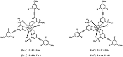
We have prepared the series of complexes, [Eu·L1–4], in which either a P-phenyl or P-methyl group is present; the former series is the more lipophilic. The nature of the peripheral phenyl substituents has also been varied, allowing the excitation wavelength to be shifted closer to 355 or 365 nm, more appropriate for typical laser or LED excitation.
The complexes were prepared using previously published methods,11,14 and were purified by reverse-phase HPLC. The brightness of each complex in methanol solution at 355 nm falls in the range 14.5 to 33 mM−1 cm−1 (Table 1 and Fig. 1). The broad absorption bands mean that at 365 nm (LED λ) the absorbance of the complexes of [Eu·L1] and [Eu·L3] was 92(±2)% of that measured at the absorption maximum. Each of the complexes dissolves readily in methanol solution and could be resolved using chiral HPLC, with columns based on chloro-substituted phenylcarbamate derivatives of cellulose or amylose (ChiralPak IC or ID: ESI†). The enantiomeric complexes eluted on the semi-preparative column with retention times differing by 8 to 18 minutes (295 K, MeOH, 4.4 mL min−1).
| Complex | λ max /nm | Normalised absorbance at 365 nm/% | Φ em/% | τ Eu/ms |
|---|---|---|---|---|
a Extinction coefficients for these complexes are 65![[thin space (1/6-em)]](https://www.rsc.org/images/entities/char_2009.gif) 000 (±5000) M−1 cm−1. Absorbance values are quoted at 365 nm as this is the LED excitation wavelength used in these experiments. Errors on quantum yield values are ±15% and on lifetimes, ±8%. 000 (±5000) M−1 cm−1. Absorbance values are quoted at 365 nm as this is the LED excitation wavelength used in these experiments. Errors on quantum yield values are ±15% and on lifetimes, ±8%.
|
||||
| [Eu·L1] | 356 | 98 | 50 | 1.18 |
| [Eu·L2] | 343 | 40 | 47 | 1.22 |
| [Eu·L3] | 355 | 100 | 55 | 1.10 |
| [Eu·L4] | 342 | 37 | 54 | 1.14 |
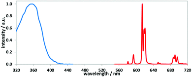 | ||
| Fig. 1 Absorption and emission spectra for [Eu·L1] (MeOH, 295 K), showing the fingerprint Eu emission profile arising from transitions from 5D0 to the 7Fn manifold (n = 0–4 shown here; see ESI† for all absorption and emission spectra). | ||
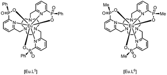
The absolute configuration was assigned by comparison of their CPL spectra (Fig. 2), assessing the sign and sequence of observed transitions in these spectra, with those measured for the parent systems, i.e. [Eu·L5] and [Eu·L6], that lack the alkynyl-aryl moiety. Configurational assignment of these archetypal complexes has been established by X-ray crystallography and CD studies in earlier work.9,14
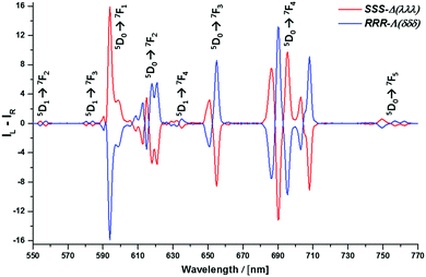 | ||
| Fig. 2 Circularly polarised luminescence spectra for the enantiomers of [Eu·L2] (red Δ; blue Λ) (5 μM complex, 4 min acquisition time, 3 averages, MeOH, 295 K); selected gem values for Δ-[Eu·L2]: −0.19 (557 nm); +0.15 (599 nm); −0.19 (655 nm); −0.32 (708 nm); see ESI† for all gem values, which are similar in size to recent reports.9,14 Similar total emission and CPL spectra were recorded for the samples on paper (Fig. 3 and Fig. S9, ESI†); for the sample immobilised on paper, the g value at 599 nm was 0.11. | ||
The high signal intensity allowed the rapid measurement of the less commonly observed 5D0–7F5 CPL transitions (ca. 755 nm), as well as CPL associated with transitions from 5D1 to 7F2,3,4. No CPL signal was observed for the 5D1–7F0,1 transitions, and the 5D0 to 7F6 manifold was not observed.
The stability of the resolved complexes to thermally-activated racemisation was examined in methanol, monitoring the appearance of the enantiomeric europium complex by analytical HPLC. No evidence for racemisation had been observed in solution at room temperature, but at 60 °C the half-life for racemisation could be measured and was found to be 410 h for [Eu·L4]. For [Eu·L2], less than 0.5% of the other enantiomer could be discerned by chiral HPLC after 21 days under these conditions. These rates were independent of complex concentration, consistent with an intramolecular process, presumably involving stepwise dissociation of the Eu–oxygen bonds leading to epimerisation at each of the P centres, and a subsequent ring inversion of the triazacyclononane ring configuration (δδδ to λλλ). The half-life for racemisation of [Eu·L4] was considerably longer than that previously recorded for the parent complex (see ESI†).14a
Time-gated photography has been achieved using an off-the-shelf DSLR camera (Nikon D5300) equipped with an i-TTL flash unit (Nikon SB910) paired with a wireless flash trigger and receiver (YN-622N). The complex [Eu·L1], fluorescein and a co-spot of both compounds were applied as a solution in methanol to non-optically brightened white paper and allowed to dry in air, creating a three-spot test paper (Scheme 1). A normal photograph under UV excitation shows, as expected, three spots of different colours (red from [Eu·L1], green from fluorescein and yellow from the co-spot). Introduction of a band pass filter (595 ± 5 nm) to the camera, led to partial disappearance of the fluorescein spot, and all of the green-coloured emission, leaving three red spots. Total loss of the fluorescein spot was not achieved due to the long tail of the fluorescein emission. However, using distance-based time gating, placing the object 1.8 m from the camera (speed of light is 0.3 m ns−1), the fluorescein spot was not observed, leaving just emission from [Eu·L1].
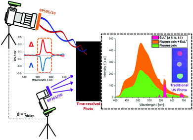 | ||
Scheme 1 Schematic set-up and proof-of-concept for time-resolved image separation using off-the shelf DSLR equipment. The three spots in the paper sample are: Λ & Δ-[EuL1] (1![[thin space (1/6-em)]](https://www.rsc.org/images/entities/char_2009.gif) : :![[thin space (1/6-em)]](https://www.rsc.org/images/entities/char_2009.gif) 1) (top); Λ & Δ-[EuL1] (1 1) (top); Λ & Δ-[EuL1] (1![[thin space (1/6-em)]](https://www.rsc.org/images/entities/char_2009.gif) : :![[thin space (1/6-em)]](https://www.rsc.org/images/entities/char_2009.gif) 1) and fluorescein (centre) and fluorescein only (bottom). The time resolved image cuts out the fluorescein emission; the applied band-pass filter selects the spectral part of interest, as further separated with respect to sign by the parallel chiroptical image analysis (in microscopy, Fig. 3). 1) and fluorescein (centre) and fluorescein only (bottom). The time resolved image cuts out the fluorescein emission; the applied band-pass filter selects the spectral part of interest, as further separated with respect to sign by the parallel chiroptical image analysis (in microscopy, Fig. 3). | ||
Chiroptical contrast based imaging, i.e. the separation of left and right handed circularly polarised light emitted by the separate Λ- and Δ-[Eu·L2] enantiomers has been facilitated via modification of a time-resolved Zeiss Axiovert 200M epifluorescence microscope set-up.15 Enantiopure Λ- and Δ-[Eu·L2] were deposited as solutions in methanol onto white paper containing no optical-brightener, and were allowed to dry at room temperature. Using a time resolved DSLR camera (Scheme 1) areas of the two enantiopure [Eu·L2] spots with equal brightness for imaging were selected (see ESI:† Fig. S1).
The microscope is equipped with a variable pulse sequence generator, which allows both CW and time-resolved operation. It comprises an even number of polished-Al mirrors (Thor Labs) after circularly polarised light translation that are used to guide the emitted light to the detectors (imaging 2D-CCD, spectral 1D-CCD and lifetime assigned photomultiplier tube). It is important to note that the transmission/DIC imaging de Sénarmont compensator of the microscope has been eliminated. The absence of this component is a vital requirement, as such a rotatable optical element consists of two broad quarter-wave plates, and the linear polariser would severely limit chiroptical selection.
The microscope is fitted with a 395 nm dichroic mirror to allow epifluorescence detection. The integral emission filter (placed in front of the detector) has been swapped for a broad (400–800 nm) wavelength, 10 mm aperture quarter-wave plate, which allows incident angle based translation of circularly polarised light into linearly polarised light. Left-handed CPL is translated to vertical linearly polarised light (V-LPL), whilst right-handed CPL is translated to horizontal LPL. The unavoidable aperture restriction, due to the nature of the commercially available quarter-wave plate, has been compensated for with a pair of variable irises and a beam expander lens pair, in a linear arrangement between the 10× objective and the filter cube, thereby eliminating light loss in the detection arm. The final optical element in the set-up is a pair of linear polarisers that allow selection and differentiation of vertically and horizontally polarised linear light. In this proof of concept instrument, (Scheme 2) we used a pair of optical polarisers (1′′; 40![[thin space (1/6-em)]](https://www.rsc.org/images/entities/char_2009.gif) 000
000![[thin space (1/6-em)]](https://www.rsc.org/images/entities/char_2009.gif) :
:![[thin space (1/6-em)]](https://www.rsc.org/images/entities/char_2009.gif) 1 extinction ratio) in a 90° orientation.
1 extinction ratio) in a 90° orientation.
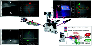 | ||
Scheme 2 Schematic set-up and proof-of-concept for CPL microscopy consisting of a Zeiss Axiovert 200M epifluorescence setup, coupled to a 365 nm UV LED (Nichia, 24V, 1.2W) and EO-1312M (Edmund Optics) camera. Chiroptical signal translation and separation is facilitated using a broad λ/4 wave plate with a pair of linear polarisers (40![[thin space (1/6-em)]](https://www.rsc.org/images/entities/char_2009.gif) 000 000![[thin space (1/6-em)]](https://www.rsc.org/images/entities/char_2009.gif) : :![[thin space (1/6-em)]](https://www.rsc.org/images/entities/char_2009.gif) 1 extinction ratio) that allow differentiation of vertically and horizontally polarised linear light. Here we used a pair of pre-aligned 1′′ optical polarisers in a 90° orientation. Images shown are: (top left) 3E and (bottom left) 3F coupled to their corresponding CPL spectra with respect to the 589/20 band pass filter used in the detection arm; (bottom right) schematic layout of a dual channel chiroptical separator assembly based on an LSCM setup, to aid optical sectioning and increased optical resolution (see ESI† for a full page view of Schemes 1 and 2). 1 extinction ratio) that allow differentiation of vertically and horizontally polarised linear light. Here we used a pair of pre-aligned 1′′ optical polarisers in a 90° orientation. Images shown are: (top left) 3E and (bottom left) 3F coupled to their corresponding CPL spectra with respect to the 589/20 band pass filter used in the detection arm; (bottom right) schematic layout of a dual channel chiroptical separator assembly based on an LSCM setup, to aid optical sectioning and increased optical resolution (see ESI† for a full page view of Schemes 1 and 2). | ||
Image acquisition using the camera was set at 7.2 ms per frame. A typical value for time gating was 8 μs, following pulsed excitation with a 365 nm UV LED (24 V, 1.2 W, ESI†). Images were collected using an accumulation sequence that can be programmed for any number of frame averages or controlled by an average FOV pixel contrast ‘saturation-limiting’ algorithm. The latter method allows images to be accumulated until a maximum contrast value of 255 is reached for any cluster of 20 pixels detected. Using this method, any difference in chiroptical contrast, determined by the gem values, is amplified as the accumulated total contrast difference between opposing chiral areas of the FOV is in proportion to the number of accumulated images. The total number of images acquired is governed by the maximum single image brightness and was automatically set to be a minimum of five times the S/N.
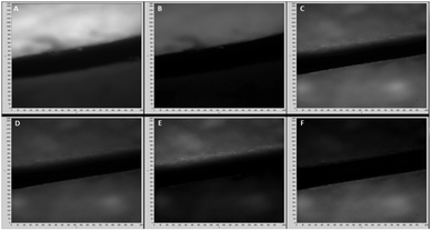
Various microscopy images were taken (Fig. 3) illustrating both time gating and chiroptical selection. Images (A) and (B) show racemic [Eu·L1] and fluorescein and demonstrate that time gating, (Scheme 1 with the DSLR camera), is also possible using optical microscopy. Images (C) and (D) show the two enantiomers of [Eu·L2] with time gating and emission wavelength selection, whilst (E) and (F) introduce the chiroptical selection (Scheme 2). Image (E) shows that when selecting for right circularly polarised light, the top piece of paper with Λ-[Eu·L2] is brighter than the bottom one. The CPL spectrum of [Eu·L2] (Fig. 2) shows strong negative CPL for the Λ-enantiomer at the wavelength of interest (∼595 nm, ΔJ = 1 transition), corresponding to more right-handed CPL. The reverse behaviour is shown in image (F). Notwithstanding the relatively small gem values, the optical setup combined with this ‘self-regulating’ imaging algorithm provides contrast ratios (CR), of the order of 3.4![[thin space (1/6-em)]](https://www.rsc.org/images/entities/char_2009.gif) :
:![[thin space (1/6-em)]](https://www.rsc.org/images/entities/char_2009.gif) 1, when observing the enantiopure lanthanide complexes (Fig. 3: E and F: see ESI† Fig. S9 for the build up of image contrast with time). In the control experiment, racemic [Eu·L1], gave rise to constant image brightness, irrespective of which channel was selected.
1, when observing the enantiopure lanthanide complexes (Fig. 3: E and F: see ESI† Fig. S9 for the build up of image contrast with time). In the control experiment, racemic [Eu·L1], gave rise to constant image brightness, irrespective of which channel was selected.
In conclusion, using a very bright Eu complex to provide CPL with a predominant handedness of circular polarisation between 585 and 605 nm, we have demonstrated the concept of chiral image contrast in emission. Chiral liquid crystal displays (LCDs), especially nematic phase LCs, can act as linear polarisers or even controllable quarter or half wave plates, based on their orientation or rotation as a function of plane crystal surface, as used for 3D projection. Here, the situation is different; chiral circularly polarised emitters are used with a linear polariser: the incident angle of circularly polarised light is always 1/8th of the wavelength with respect to the axis of travel to the polariser at a point (rather than a slit, with linear polarised light). Rotating a linear polariser in the detection set-up, with circularly polarised emitted light does not make any contrast difference as a function of rotation angle.
In this example, circularly polarised light is translated to well-defined linearly polarised light using the birefringent quarter-wave plate and the linear polariser. In such a setup, two linear polarisers separate the horizontal and vertical linearly polarised light generated. The H-LPL and V-LPL are a direct, wavelength-independent representation of the initially emitted left and right-handed CP light. This study therefore suggests a role for applications using the CPL emission of such Eu complexes in security tagging, among other possibilities.
We acknowledge the ERC (FCC 266804), EPSRC and Royal Society (RP) for support, and Prof. Andrew Beeby for fruitful discussions and help concerning the optical set ups.
Notes and references
- (a) F. Zinna and L. Di Bari, Chirality, 2015, 27, 1 CrossRef CAS PubMed; (b) J. P. Riehl and F. S. Richardson, Chem. Rev., 1986, 86, 1 CrossRef CAS; (c) R. Carr, N. H. Evans and D. Parker, Chem. Soc. Rev., 2012, 41, 7673 RSC.
- (a) G. Muller, Dalton Trans., 2009, 9692 RSC; (b) T. Wu, X.-Z. You and P. Bour, Coord. Chem. Rev., 2015, 284, 1 CrossRef CAS.
- (a) J. A. Kitchen, D. E. Barry, L. Mercs, M. Albrecht, R. D. Peacock and T. Gunnlaugsson, Angew. Chem., Int. Ed. Engl., 2012, 51, 704 CrossRef CAS PubMed; (b) K. Okutani, K. Nozaki and M. Iwamura, Inorg. Chem., 2014, 53, 5527 CrossRef CAS PubMed; (c) M. Seitz, K. Do, A. J. Ingram, E. G. Moore, G. Muller and K. N. Raymond, Inorg. Chem., 2009, 48, 8469 CrossRef CAS PubMed.
- S. D. Pietro and L. Di Bari, Inorg. Chem., 2012, 51, 12007 CrossRef PubMed.
- (a) J.-C. G. Bunzli, Chem. Rev., 2010, 110, 2729 CrossRef PubMed; (b) M. C. Heffern, L. M. Matosiuk and T. J. Meade, Chem. Rev., 2014, 114, 4496 CrossRef CAS PubMed.
- (a) E. G. Moore, A. P. S. Samuel and K. N. Raymond, Acc. Chem. Res., 2009, 42, 542 CrossRef CAS PubMed; (b) J. Xu, T. M. Corneille, E. G. Moore, G.-L. Law, N. G. Butlin and K. N. Raymond, J. Am. Chem. Soc., 2011, 133, 19900 CrossRef CAS PubMed.
- S. J. Butler, L. Lamarque, R. Pal and D. Parker, Chem. Sci., 2014, 5, 1750 RSC.
- A.-S. Chauvin, S. Comby, B. Song, C. D. B. Vandevyver, F. Thomas and J.-C. G. Bunzli, Chem. – Eur. J., 2007, 13, 9515 CrossRef CAS PubMed.
- (a) J. W. Walton, L. Di Bari, D. Parker, G. Pescitelli, H. Puschmann and D. S. Yufit, Chem. Commun., 2011, 47, 12289 RSC; (b) J. W. Walton, R. Carr, N. H. Evans, A. M. Funk, A. M. Kenwright, D. Parker, D. S. Yufit, M. Botta, S. De Pinto and K. L. Wong, Inorg. Chem., 2012, 51, 8042 CrossRef CAS PubMed.
- M. Delbianco, V. Sadovnikova, E. Bourrier, G. Mathis, L. Lamarque, J. M. Zwier and D. Parker, Angew. Chem., Int. Ed. Engl., 2014, 53, 10718 CrossRef CAS PubMed.
- M. Soulie, F. Latzko, E. Bourrier, V. Placide, S. J. Butler, R. Pal, J. W. Walton, P. L. Baldeck, B. Le Guennic, C. Andraud, J. M. Zwier, L. Lamarque, D. Parker and O. Maury, Chem. – Eur. J., 2014, 20, 8636 CrossRef CAS PubMed.
- S. J. Butler, M. Delbianco, L. Lamarque, B. K. McMahon, E. R. Neil, R. Pal, D. Parker, J. W. Walton and J. M. Zwier, Dalton Trans., 2015, 44, 4791 RSC.
- E. R. Neil, M. A. Fox, R. Pal and D. Parker, Dalton Trans., 2016, 45, 8355 RSC.
- (a) N. H. Evans, R. Carr, M. Delbianco, R. Pal, D. S. Yufit and D. Parker, Dalton Trans., 2013, 42, 15610 RSC; (b) E. R. Neil, A. M. Funk, D. S. Yufit and D. Parker, Dalton Trans., 2014, 43, 5490 RSC; (c) S. J. Butler, M. Delbianco, N. H. Evans, A. T. Frawley, R. Pal, D. Parker, R. S. Puckrin and D. S. Yufit, Dalton Trans., 2014, 43, 5721 RSC.
- R. Pal and A. Beeby, Methods Appl. Fluoresc., 2014, 2, 037001 CrossRef.
Footnote |
| † Electronic supplementary information (ESI) available: Complex synthesis, optical measurements, microscope technical details. See DOI: 10.1039/c6cc07313a |
| This journal is © The Royal Society of Chemistry 2016 |

