
 Open Access Article
 This Open Access Article is licensed under a
 Creative Commons Attribution 3.0 Unported Licence
Mechanistic insights into sodium storage in hard carbon anodes using local structure probes†
Joshua M.
Stratford
 a,
Phoebe K.
Allan
abc,
Oliver
Pecher
a,
Philip A.
Chater
c and
Clare P.
Grey
*a
a,
Phoebe K.
Allan
abc,
Oliver
Pecher
a,
Philip A.
Chater
c and
Clare P.
Grey
*a
aDepartment of Chemistry, University of Cambridge, Lensfield Road, Cambridge, CB2 1EW, UK. E-mail: cpg27@cam.ac.uk
bGonville and Caius College, Trinity Street, Cambridge, CB2 1TA, UK
cDiamond Light Source Ltd., Harwell Science and Innovation Campus, Didcot, OX11 0DE, UK
First published on 22nd September 2016
Abstract
Operando 23Na solid-state NMR and pair distribution function analysis experiments provide insights into the structure of hard carbon anodes in sodium-ion batteries. Capacity results from “diamagnetic” sodium ions first adsorbing onto pore surfaces, defects and between expanded layers, before pooling into larger quasi-metallic clusters/expanded carbon sheets at lower voltages.
Sodium-ion batteries are an attractive option for low-cost and environmentally benign energy-storage technologies. Whilst graphite shows almost no ability to store sodium electrochemically, non-graphitizable hard carbons demonstrate good reversible capacity and are among the cheapest proposed anode materials to date.1–3 Early studies reported two electrochemical processes: a sloping region followed by a process close to 0 V versus sodium. By analogy with the lithium system, it was suggested that sodium insertion proceeded via a two-stage mechanism associated with these two electrochemical signals: intercalation of sodium between nearly parallel layers, followed by the formation of metallic species within the pores of the material at low voltages,4 experimental support for this mechanism coming from small-angle X-ray scattering data.5 These studies indicated that pores are filled during the low-voltage process, the same authors later attributing a change in intensity of the graphitic (002) reflection to sodium intercalation within the structure.2 However, other reports propose alternative mechanisms. For example, Gotoh et al. did not observe metallic sodium environments in ex situ23Na solid-state nuclear magnetic resonance (ssNMR) studies.6 Recent density functional theory (DFT) calculations generated similar electrochemical profiles to those seen experimentally through consideration of intercalation alone: at higher voltages, Na intercalates near mono- and di-vacancy defects, essentially complete charge transfer to the carbon sheets takes place (charge primarily being localised near the defects) resulting in ionic Na+ ions. This increased iconicity was proposed to help to overcome the van der Waals attractions holding the graphene layers together.7 The low voltage region is then ascribed to further intercalation in graphitic interlayer spaces near the defects, in combination with intercalation between layers with larger interlayer spaces. Most recently, a range of hard carbons at different annealing temperatures were prepared, and the number of structural defects was quantified via the ratio of the areas of the Raman G and D band peaks.8 A correlation between the D
![[thin space (1/6-em)]](https://www.rsc.org/images/entities/char_2009.gif) :G band ratio and the observed capacity during the sloping region was then observed, intercalation being proposed to occur at lower voltages. The same authors presented pair distribution function (PDF) analysis of neutron scattering data for their carbons, analysing the size of the graphene domains in these materials. In the following, we explore the different proposed mechanisms for sodium insertion, studying a commercial hard carbon using X-ray total scattering PDF analysis and 23Na ssNMR. We see distinct electronic and local structures for the Na inserted in the higher and lower voltage processes.
:G band ratio and the observed capacity during the sloping region was then observed, intercalation being proposed to occur at lower voltages. The same authors presented pair distribution function (PDF) analysis of neutron scattering data for their carbons, analysing the size of the graphene domains in these materials. In the following, we explore the different proposed mechanisms for sodium insertion, studying a commercial hard carbon using X-ray total scattering PDF analysis and 23Na ssNMR. We see distinct electronic and local structures for the Na inserted in the higher and lower voltage processes.
The PDF for the pristine hard carbon, derived from the Fourier transform of the corrected, normalised total scattering data, is shown in Fig. 1a. The position of peaks in the PDF, which correspond to atom–atom distances within the structure, are well-matched to those in a graphene fragment. The position and intensity of peaks at interatomic distances, r, greater than 5 Å deviate strongly from those observed in the PDF for graphite (Fig. S2, ESI†), implying non-parallel stacking of graphene fragments within the hard carbon. Peaks are observed until around 25 Å. The loss of the correlations beyond this distance arises from disorder within the structure; a combination of sheet curvature (caused in part by defects within the graphene sheets) or termination of the carbon fragments is likely to be responsible. Curvature may result from small numbers of non-hexagonal carbon rings; however, our PDF data does not show major correlations at the expected distances for 5- or 7-membered rings (2.34 and 3.2 Å, respectively), indicating that any such features can only be present in small concentrations.9
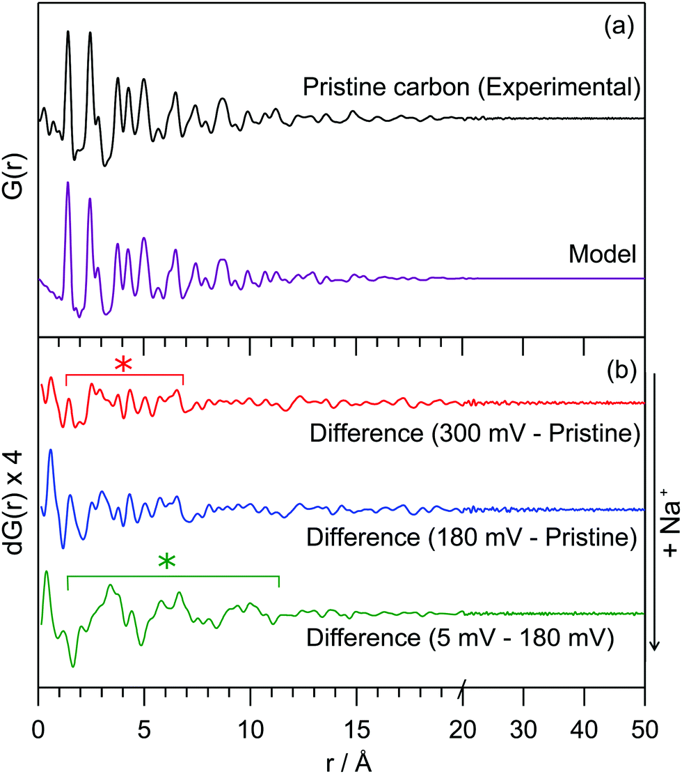 | ||
| Fig. 1 (a) Experimental PDF data for pristine hard carbon and a PDF simulated using a turbostratically disordered graphite model (offset below); (b) difference PDFs of hard carbon anodes at various states of charge. The red line (top) corresponds to a sample discharged to 300 mV, the blue (middle) to 180 mV and the green (bottom) to 5 mV. Difference PDFs were r-averaged over termination ripples. The red * highlights the range over which additional interactions are formed in the high-voltage process, the green * highlights the additional interactions observed during the low-voltage process. Weaker peaks are a result of minor changes to the carbon structure and termination ripples. Full data and further details can be found in the ESI.† | ||
The experimental PDF can be simulated using a starting model of graphite, with large displacement parameters in the c-lattice direction; this is used to model disorder between fragments (i.e., layer stacking) (model in Fig. 1a). An extended unit cell parameter in the c-direction accounts for the lower density of the hard carbon compared to graphite (1.52 g cm−3 compared to typical values of 2.26 g cm−3).10,11 This model can account for significant turbostratic disorder in the material, as has been suggested by PDF studies of similar materials.8,9,12
Real-space least-squares refinements of this graphite-derived model against experimental PDF data are unable to fit the entire r-range of the dataset using a single value for the a-lattice parameter. Instead, we discover a systematic decrease of the a-parameter in refinements against data in longer interatomic distance ranges. The PDF simulated for a planar graphene sheet using the a-parameter obtained from refinement of the model against low-r peaks (1–5 Å) consistently overestimates the position of peaks at high-r (>10 Å). This means that atoms in the graphene sheet are found to be systematically closer together with increasing r than would be predicted by a planar arrangement, implying a significant degree of curvature of the fragments. We estimate the average radius of curvature for the graphene fragments as approximately 16 Å. Further details of these refinement calculations are given in the ESI.† This result implies a more complex arrangement of fragments in space than the commonly used “house-of-cards” model.4,13 Notably, we would expect fewer parallel layers and a wider range of interlayer spaces.
Operando 23Na ssNMR experiments are able to probe different local atomic environments present during cycling, and additionally are not susceptible to degradation or relaxation effects that might affect the ex situ results.14 Two peaks at −10 ppm and 1135 ppm are observed for the pristine electrochemical cell corresponding to the NaPF6 electrolyte and the sodium metal counter electrode, respectively (Fig. 2). During the initial sloping electrochemical process, down to a voltage of 0.8 V, only changes to the intensity in the region around 0 ppm are observed. This is consistent with either the formation of diamagnetic species within the bulk of the electrode or of electrolyte decomposition on the surface to form the solid-electrolyte interphase (SEI) layer. At voltages lower than 0.8 V, an additional signal at approximately −40 ppm emerges and grows in intensity. Throughout the low voltage region of the electrochemistry, (i.e., below 180 mV) this peak continues to grow but now proceeds to shift to higher frequencies, finally reaching 760 ppm at the end of sodium insertion. Upon sodium removal, the reverse of these processes occurs, returning to a spectrum showing only the original two features. The behaviour is identical on subsequent cycles.
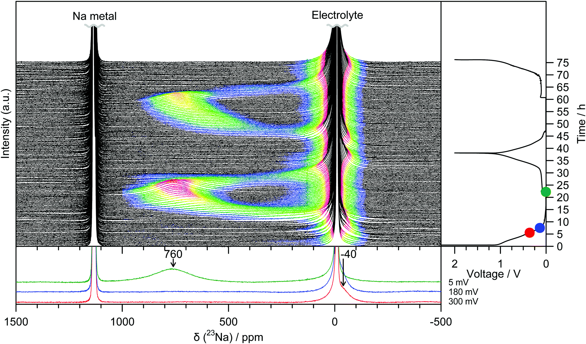 | ||
| Fig. 2 Operando 23Na NMR spectra for an electrochemical cell with sodium metal and hard carbon electrodes, and NaPF6 electrolyte. Strong features corresponding largely to the electrolyte or metal have been truncated for clarity. Spectra are coloured in the region −200 to 1000 ppm according to their intensity. The corresponding electrochemistry is shown on the right-hand side and selected spectra are offset below. The cell was cycled at a rate of C/20 (corresponding to achieving a capacity of 300 mA h g−1 in 20 hours) between 2 and 0.05 V, and held at the end of each discharge until the current dropped to below C/100. The coulombic efficiency for the 1st cycle is 84% owing to additional capacity observed during discharge as a result of electrolyte breakdown to form an SEI layer. The coulombic efficiency increases to 97% for the 2nd cycle. | ||
Ex situ 23Na magic-angle spinning (MAS) ssNMR spectra were obtained in order to gain additional resolution in the diamagnetic shift region without overlap from an electrolyte signal (Fig. 3 and Fig. S8, ESI†). The spectra are consistent with the operando measurements; two regions of intensity are observed with peak maxima at −70 ppm and 660 ppm, which appear at similar states of charge to the operando measurements. It should be noted that differences in the value of the shift between static and MAS spectra are commonly observed owing to bulk magnetic susceptibility effects.15 Additional peaks in the ex situ spectra are assigned to sodium present in the SEI and residual electrolyte (ESI†). The observation of the shifted peaks at positive frequencies in the ex situ spectra is highly dependent on the time for which the cell was allowed to rest prior to recovering the electrode, with relaxation occurring over the course of several hours; this observation indicates that the material formed after sodium insertion continues to react with electrolyte resulting in self-discharge and oxidation of the electrode. The samples, once extracted from the cell, were also found to be highly air and moisture sensitive and extreme care needed to be taken to prevent unwanted side reactions; these factors may explain why peaks in this frequency range were not observed in the previously reported 23Na NMR spectra.6
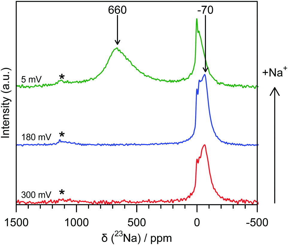 | ||
| Fig. 3 Ex situ 23Na 60 kHz MAS NMR spectra of hard carbon anodes at various states of charge. The red spectrum (bottom) corresponds to a sample discharged to 300 mV, the blue (middle) to 180 mV and the green (top) to 5 mV. Shifts are indicated for peaks not resulting from SEI or electrolyte. Spinning sidebands are indicated with an asterisk (*). Additional spectra are given in the ESI.† | ||
Additional spectra obtained at two different magnetic fields (Fig. S9, ESI†) indicate that the shift of the signal with a peak maximum at −70 ppm is dominated by second order quadrupolar coupling. Fits of these spectra (see ESI†) reveal an isotropic shift of approximately −4 ppm, this small negative shift being at least in part ascribed to the ring current (local field) effects observed for ions above graphene sheets and fragments.16,17 This indicates that the sodium that is initially inserted at higher voltages is ionic in nature, implying essentially complete transfer of spin density from a Na atom to the carbon sheets, i.e., the presence of Na+ ions. Furthermore, this observation suggests that there is little disruption to the aromatic ring currents that give rise to this phenomenon during the sloping region, consistent with mechanisms that localise charge near the carbon defects and not throughout the graphene sheets. We therefore suggest that sodium is largely deposited on pore walls and in interlayer regions, most likely near defects.
The shift of the resonance to positive frequencies during the low voltage region of the electrochemistry, observed both during the operando experiment and ex situ (Fig. S8, ESI†), indicates that the local structural and/or electronic environment of the sodium ions that were inserted at higher potentials changes as more sodium is incorporated into the structure at lower potentials. This shift is due to an increased contribution from the Knight shift, which arises from the interaction of the nuclear spins with the unpaired electrons located at the Fermi level of the conduction band,15 larger shifts indicating an increase of the Na 2s density of states at the Fermi level. This implies that the sodium species becomes increasingly metallic during this period of the electrochemistry. We ascribe this process to Na+ intercalation between appropriately-spaced disordered graphene layers, along with further insertion into empty environments nearby the defects, insertion now resulting in a reduction of the more ordered graphene sheets. The Na+−C interaction gradually becomes less ionic as the carbon is reduced, affecting the shifts of sodium already in environments close to the defects. Secondly, where pores are sufficiently large, extended sodium clusters are formed that are more metallic in nature, resulting in even larger Knight shifts. This is consistent with DFT calculations and experimental data, suggesting the importance of defects,7,8 and which also suggest that any clusters formed may be two dimensional in nature, reflecting the insertion between the expanded graphene sheets, and with SAXS measurements which imply that the carbon pores are filled at lower voltages.5
7Li operando ssNMR measurements on similar electrode materials exhibit a peak at low-voltage which is shifted to approximately 40% of that of lithium metal.18,19 This is significantly higher than for stage 1 graphite intercalation compounds (GIC), which is presented as evidence for quasimetallic lithium contained in pores. In comparison, the peak at the end of sodium insertion is found shifted to much higher values, almost 70% the shift of sodium metal. In both cases, it is possible that the larger shift is in part due to insertion between carbon sheets with larger interlayer spacing. In addition, we note that the first 23Na resonance to appear (−40 ppm) does not appear to shift during the sloping region of the electrochemistry. This is in contrast to the 7Li measurements, where the first peak shifts from 0 to 18 ppm during the same period.18,19 However, such a shift in the sodium spectra could be masked by the strong electrolyte signal around −10 ppm or could be a result of using a different hard carbon than was used in the published lithium spectra.
Our preliminary PDF measurements for the electrodes after sodium insertion are consistent with this interpretation of the NMR data. A differential PDF, where the PDF for the pristine carbon is subtracted from the PDF at various points of discharge, highlights additional interactions present on the insertion of sodium (Fig. 1b): samples discharged to 300 mV and 180 mV along the sloping region show only minor features at very low-r (<7 Å), shown by the red asterisk in Fig. 1b. A differential PDF between the samples discharged to 180 mV and 5 mV, obtained by subtracting the PDF for the sample discharged to 180 mV from the PDF of the sample discharged to 5 mV, shows the additional structure forming during the low potential electrochemical process (Fig. 1b, bottom) implying clusters with a correlation length of approximately 10 Å are formed during the low-voltage region. These interactions are locally similar to those found in sodium-metal (Fig. S7, ESI†). This is consistent with increased Na ordering in this regime consistent with intercalation and/or Na pooling.
These results highlight new mechanistic aspects of the electrochemical insertion of sodium into hard carbons. Operando23Na ssNMR spectra are dominated by a single resonance, initially present close to 0 ppm, then shifting to positive frequencies. This is consistent with a two-stage mechanism. Ionic sodium ions are formed in the sloping region, consistent with charge localization, presumably near defects. Since defects are also responsible for creating regions with larger interplanar distances, some insertion between larger spaced graphene sheets may commence in this region, again this being associated with charge localization. At lower voltages, increased charge transfer to the Na+ ions occurs, the ions becoming progressively more metallic. In this region, intercalation and Na pooling occurs, forming Na clusters or domains with coherence lengths of >10 Å. PDF data additionally indicates that the turbostratically disordered, graphene-like fragments exhibit significant curvature. This will have significant effects on the interlayer arrangements and thus the regions which are available for sodium insertion. Our results imply that control of the pore architecture during synthesis could determine the size of sodium clusters formed, and thus grant the ability to tune the relative capacities of the high- and low-voltage processes.
We thank Diamond Light Source for the provision of beamtime on XPDF (I15-1) and access to beamline I15 (EE8840, EE13681) that contributed to the results presented here. The authors thank Dr Nicole Trease, Dr John Griffin, Dr Alex Forse and Dr Céline Merlet for useful discussions. J. M. S. acknowledges funding from EPSRC and the European Commission under grant agreement no. 696656 (Graphene Flagship). P. K. A. acknowledges the School of the Physical Sciences of the University of Cambridge for funding through an Oppenheimer Research Fellowship and a Junior Research Fellowship from Gonville and Caius College, Cambridge. This project has received funding from the European Union's Horizon 2020 research and innovation programme under the Marie Skłodowska-Curie grant agreement No. 655444 (O. P.). Additional data related to this publication are available: http://dx.doi.org/10.17863/CAM.4587.
Notes and references
- M. M. Doeff, Y. Ma, S. J. Visco and L. C. De Jonghe, J. Electrochem. Soc., 1993, 140, L169–L170 CrossRef CAS.
- D. A. Stevens and J. R. Dahn, J. Electrochem. Soc., 2001, 148, A803–A811 CrossRef CAS.
- E. Irisarri, A. Ponrouch and M. R. Palacin, J. Electrochem. Soc., 2015, 162, A2476–A2482 CrossRef CAS.
- D. A. Stevens and J. R. Dahn, J. Electrochem. Soc., 2000, 147, 1271–1273 CrossRef CAS.
- D. A. Stevens and J. R. Dahn, J. Electrochem. Soc., 2000, 147, 4428–4431 CrossRef CAS.
- K. Gotoh, T. Ishikawa, S. Shimadzu, N. Yabuuchi, S. Komaba, K. Takeda, A. Goto, K. Deguchi, S. Ohki, K. Hashi, T. Shimizu and H. Ishida, J. Power Sources, 2013, 225, 137–140 CrossRef CAS.
- P.-c. Tsai, S.-C. Chung, S.-k. Lin and A. Yamada, J. Mater. Chem. A, 2015, 3, 9763–9768 CAS.
- C. Bommier, T. W. Surta, M. Dolgos and X. Ji, Nano Lett., 2015, 15, 5888–5892 CrossRef CAS PubMed.
- A. C. Forse, C. Merlet, P. K. Allan, E. K. Humphreys, J. M. Griffin, M. Aslan, M. Zeiger, V. Presser, Y. Gogotsi and C. P. Grey, Chem. Mater., 2015, 27, 6848–6857 CrossRef CAS.
- M. B. Dowell and R. A. Howard, Carbon, 1986, 24, 311–323 CrossRef.
- http://www.kureha.co.jp/development/story/pdf/catalog_hc_eg_20120924.pdf, accessed August 2016.
- V. Petkov, R. G. Difrancesco, S. J. L. Billinge, M. Acharya and H. C. Foley, Philos. Mag. B, 1999, 79, 1519–1530 CrossRef CAS.
- J. R. Dahn, T. Zheng, Y. Liu and J. S. Xue, Science, 1995, 270, 590–593 CAS.
- F. Blanc, M. Leskes and C. P. Grey, Acc. Chem. Res., 2013, 46, 1952–1963 CrossRef CAS PubMed.
- N. M. Trease, L. Zhou, H. J. Chang, B. Y. Zhu and C. P. Grey, Solid State Nucl. Magn. Reson., 2012, 42, 62–70 CrossRef CAS PubMed.
- P. Lazzeretti, Prog. Nucl. Magn. Reson. Spectrosc., 2000, 36, 1–88 CrossRef CAS.
- A. C. Forse, J. M. Griffin, V. Presser, Y. Gogotsi and C. P. Grey, J. Phys. Chem. C, 2014, 118, 7508–7514 CAS.
- M. Letellier, F. Chevallier, C. Clinard, E. Frackowiak, J.-N. Rouzaud, F. Béguin, M. Morcrette and J.-M. Tarascon, J. Chem. Phys., 2003, 118, 6038–6045 CrossRef CAS.
- M. Letellier, F. Chevallier, F. Béguin, E. Frackowiak and J. N. Rouzaud, J. Phys. Chem. Solids, 2004, 65, 245–251 CrossRef CAS.
Footnote |
| † Electronic supplementary information (ESI) available: Experimental details, full PDF data and refinements, additional NMR spectra and fits. See DOI: 10.1039/c6cc06990h |
| This journal is © The Royal Society of Chemistry 2016 |