 Open Access Article
A Z-scheme photocatalyst constructed with an yttrium–tantalum oxynitride and a binuclear Ru(II) complex for visible-light CO2 reduction†
Kanemichi
Muraoka
a,
Hiromu
Kumagai
a,
Miharu
Eguchi
b,
Osamu
Ishitani
*a and
Kazuhiko
Maeda
*a
aDepartment of Chemistry, School of Science, Tokyo Institute of Technology, 2-12-1-NE-2 Ookayama, Meguro-ku, Tokyo 152-8550, Japan. E-mail: ishitani@chem.titech.ac.jp; maedak@chem.titech.ac.jp
bElectronic Functional Materials Group, Polymer Materials Unit, National Institute for Materials Science, 1-1 Namiki, Tsukuba, Ibaraki 305-0044, Japan
First published on 23rd May 2016
Abstract
An yttrium–tantalum oxynitride having a band gap of 2.1 eV (absorbing visible light at <580 nm) was applicable as a semiconductor component of a Z-scheme CO2 reduction system operable under visible light, in combination with a binuclear Ru(II) complex that has strong absorption in the visible region (<600 nm). Excitation of this system with visible light under a CO2 atmosphere induced photocatalytic formation of formic acid with very high selectivity (>99%).
In order to address the depletion of fossil fuels and the concomitant emission of CO2, the chemical fixation of CO2 as well as its conversion into useful compounds are currently important topics in the field of chemistry. Various reactions/schemes have been proposed to date for this purpose.1–12 Among these, photocatalytic CO2 reduction using a heterogeneous photocatalyst that consists of a semiconductor and a metal complex has great potential because it is a readily scalable process that utilizes only low-density sunlight.13
From the viewpoint of solar energy conversion, a semiconductor photocatalyst that harvests a wide range of visible light is highly desirable. Recently, it has been reported that certain metal oxides modified with Ag as a promoter achieved CO2 reduction using water as the electron source.7 However, the band gaps of these metal oxides are too large to harvest visible light. While our group has developed heterogeneous photocatalysts for CO2 reduction that consist of a visible-light-responsive semiconductor and a functional metal complex working as an oxidation and a reduction site, respectively, these novel semiconductors (e.g., TaON, CaTaO2N and C3N4) can harvest visible light only at wavelengths shorter than 500 nm.9–11 Unfortunately, there are very few semiconductors that have a band gap smaller than 2.5 eV (corresponding to 500 nm wavelength) and that can be applied for photocatalytic CO2 reduction. Reducing the band gap of a semiconductor will reduce the reactivity of electrons and holes generated in the conduction and valence bands, respectively. At the same time, it will become difficult to satisfy thermodynamic requirements; that is, valence and conduction band potentials that straddle the redox potentials of a desired reaction. Because a CO2 fixation system using metal-complex/semiconductor hybrid photocatalysts ultimately requires the use of water as the electron source, a semiconductor photocatalyst has to satisfy band edge potentials that straddle both the water oxidation and CO2 reduction potentials.
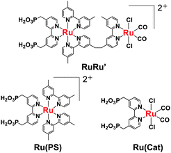
Herein we report that an yttrium–tantalum oxynitride (YTON) having a band gap of 2.1 eV coupled with a binuclear Ru(II) complex (RuRu′, see Chart 1) works as a photocatalyst for reduction of CO2 to formic acid under visible-light irradiation. This system works according to the Z-scheme principle; i.e., excitation of both YTON and the redox photosensitizer unit of RuRu′ with visible light induces reduction of CO2 to HCOOH with >99% selectivity at room temperature and ambient atmospheric pressure.
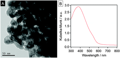
The YTON powder was prepared by the conventional thermal ammonolysis of a corresponding Y–Ta oxide precursor that was previously synthesized using the polymerized complex (PC) method. The details of these two procedures are provided in the ESI†. The synthesis of single-phase pyrochlore Y2Ta2O5N2 was confirmed by X-ray diffraction (XRD) analysis (Fig. S1, ESI†). Energy-dispersive X-ray (EDX) spectroscopy and thermogravimetric (TG) analysis of the as-prepared YTON determined that the Y/Ta ratio was 0.95, and that the concentration of nitrogen in the material was 1.2 wt%, values that were below the theoretical values (Y/Ta = 1, N: 4.3 wt%), indicating a non-stoichiometric composition. TEM observations showed that the YTON consisted of 20–30 nm primary particles connected to one another to form larger secondary particles with porous structures (Fig. 1A). The specific surface area of the YTON was determined by nitrogen adsorption/desorption to be 16 m2 g−1, a result that can be attributed to its porous structure. As shown in Fig. 1B, the YTON had an absorption edge at approximately 580 nm, consistent with an earlier report.14 The band gap of the material was estimated to be about 2.1 eV based on the onset wavelength of its diffuse reflectance spectrum.
Li et al. have reported that yttrium–tantalum oxynitride exhibits photocatalytic activity for both water reduction and oxidation under visible light.14 However, the band-edge potentials of the material have not been reported and remain unclear. Therefore, we conducted photoelectrochemical analyses in order to investigate the band-gap structure.15 The actual band-edge positions were evaluated by measuring the onset potentials of photocurrents generated from an IrO2/TiO2/YTON/FTO electrode in electrolyte solutions with various pH values. In these experiments, the YTON was immobilized on the FTO by a conventional squeegee method and a TiO2 layer was deposited to improve the inter-particle electron transfer and particle/substrate electron transfer.15a,16 In addition, colloidal IrO2 was deposited on the TiO2/YTON to enhance the water oxidation.16b
Current–voltage curves were acquired under chopped visible light irradiation (λ > 500 nm), scanning from negative to positive potential at 5 mV s−1 in an aqueous Na2SO4 solution adjusted to pH 4.8, 8.7 or 11.7 by the addition of H2SO4 or NaOH. As shown in Fig. S2 (ESI†), an anodic photocurrent attributed to water oxidation was observed under all pH conditions examined, indicating that the YTON functions as an n-type semiconductor. The onset potential, corresponding to the flat-band potential (EFB), was shifted to the negative direction with increasing pH. The energy difference between the conduction band edge potential (ECB) and the EFB is believed to be approximately 0.1–0.3 eV based on the n-type semiconducting character of the YTON.17 On the basis of the YTON band gap (2.1 eV), the valence band edge potential (EVB) can be estimated to be 2.1 V more positive than ECB. Fig. 2 presents the conduction and valence band edge potentials of the IrO2/TiO2/YTON/FTO electrode as a function of pH. The positions of the YTON conduction band minimum and the valence band maximum evidently vary with pH, and were shifted at a rate of approximately −17 mV per pH as the pH increased. It was thus shown that YTON had band-edge potentials suitable for water oxidation in all pH range examined. Under basic pH conditions, however, it is clear that the driving force for CO2 reduction becomes insufficient.
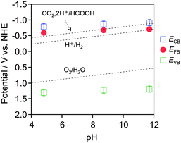 | ||
| Fig. 2 Dependence of conduction and valence band edge potentials for the as-prepared YTON on the pH of the electrolyte, as determined from photocurrent measurements (see Fig. S2, ESI†). | ||
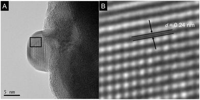
Prior to photocatalytic reaction, the YTON was modified with both Ag and RuRu′ having methylphosphonic-acid anchoring groups, which, respectively, work as a promoter for interfacial electron transfer and as another photocatalytic unit with high capability for CO2 reduction.10b,11 TEM observations indicated that metallic Ag nanoparticles approximately 10 nm in size were distributed on the YTON surface (Fig. 3A). The resulting lattice fringe had a period of 0.24 (Fig. 3B), consistent with the d spacing of Ag(111) planes. The successful immobilization of RuRu′ on Ag/YTON was verified by means of Fourier transform infrared (FT-IR) spectroscopy (Fig. S3, ESI†).
Using the as-prepared YTON with Ag and/or RuRu′, CO2 reduction was performed under visible light irradiation (λ > 400 nm). The reaction setup used in this work was identical to that we have reported previously.10,11Table 1 summarizes the results. To avoid complications resulting from water oxidation catalysis, reactions were conducted in a mixed N,N-dimethylacetamide (DMA)/triethanolamine (TEOA) solution (4![[thin space (1/6-em)]](https://www.rsc.org/images/entities/char_2009.gif) :
:![[thin space (1/6-em)]](https://www.rsc.org/images/entities/char_2009.gif) 1 v/v), where TEOA worked as a sacrificial electron donor.
1 v/v), where TEOA worked as a sacrificial electron donor.
| Entry | Photocatalyst | Amount of HCOOH/nmol | TON | Selectivity |
|---|---|---|---|---|
a Reaction conditions: photocatalyst, 8.0 mg (Ag 1.5 wt%); solution, a mixture of DMA and TEOA (4![[thin space (1/6-em)]](https://www.rsc.org/images/entities/char_2009.gif) : :![[thin space (1/6-em)]](https://www.rsc.org/images/entities/char_2009.gif) 1 v/v) 4.0 mL; light source, 400 W high-pressure Hg lamp (SEN) with a NaNO2 solution filter. Reaction time: 24 h. The amount of metal complex loaded in each case was 4.5 µmol g−1.
b Under an Ar atmosphere.
c Without TEOA.
d In the dark. 1 v/v) 4.0 mL; light source, 400 W high-pressure Hg lamp (SEN) with a NaNO2 solution filter. Reaction time: 24 h. The amount of metal complex loaded in each case was 4.5 µmol g−1.
b Under an Ar atmosphere.
c Without TEOA.
d In the dark.
|
||||
| 1 | RuRu′/YTON | 162 | 5 | >99 |
| 2 | RuRu′/Ag/YTON | 630 | 18 | >99 |
| 3 | YTON | N.D. | — | — |
| 4 | Ag/YTON | N.D. | — | — |
| 5 | RuRu′ (6.0 µM) | N.D. | — | — |
| 6b | RuRu′/Ag/YTON | N.D. | — | — |
| 7c | RuRu′/Ag/YTON | N.D. | — | — |
| 8d | RuRu′/Ag/YTON | N.D. | — | — |
| 9 | Ru(PS)/Ag/YTON | N.D. | — | — |
| 10 | Ru(Cat)/Ag/YTON | N.D. | — | — |
Combining YTON with RuRu′ resulted in clearly observable HCOOH production with very high selectivity (>99%) and catalytic turnover numbers (TONHCOOH) of 5 based on the amount of loaded RuRu′ (entry 1). The Ag-modification increased the HCOOH formation (TONHCOOH = 18, entry 2). This is attributed to the promotional effect of the Ag, which facilitates interfacial electron transfer from the semiconductor to the excited state of the binuclear Ru(II) complex,10b,11 as discussed below. The generation of HCOOH over RuRu′/Ag/YTON was improved with increases in the amount of Ag loaded, up to 1.5 wt%, beyond which the yield began to decrease (Fig. S4, ESI†). By contrast, neither the YTON nor the Ag/YTON showed activity for the reaction (entries 3 and 4). Note that TEOA cannot reductively quench the photosensitizer unit of RuRu′, i.e., it is reasonable that only RuRu′ without YTON did not induce photocatalytic reduction of CO2 (entry 5 in Table 1). In the absence of CO2 or TEOA, no HCOOH production was observed (entries 6 and 7), nor was there any reaction under dark conditions (entry 8). It should be noted that neither CO nor H2 gas evolution was observed in all cases. No C–C coupling product (e.g., ethane and ethanol) was detected as well. These results show that both YTON and RuRu′ are essential to realize HCOOH production, and that TEOA works as an electron donor to scavenge holes in the valence band of the YTON.
When using Ag/YTON modified with either a model mononuclear complex of the redox photosensitizer unit (Ru(PS)) or the catalytic model complex (Ru(Cat)), no HCOOH production could be detected (entries 9 and 10). Ru(Cat) has been shown to function as a cocatalyst for CO2 reduction to generate HCOOH on certain semiconductors (such as C3N4 and CaTaO2N),9,10b but it was evidently not effective in conjunction with YTON, probably because of the lower conduction-band potential.
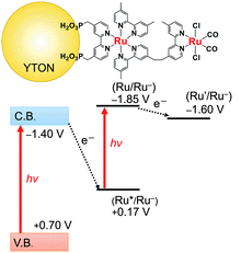
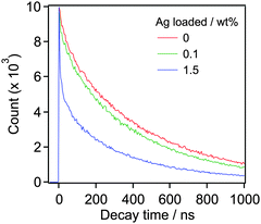
Fig. 4 presents an energy diagram for RuRu′/YTON based on the results of photoelectrochemical measurements (Fig. 2) and our previous study.10a Upon visible light irradiation (λ > 400 nm), both the YTON and the photosensitizing unit of the RuRu′ undergo excitation. In this case, it should be noted that electron transfer from the excited state of RuRu′ (Eox* = −1.30 V) to the conduction band of the YTON (−1.40 V) is energetically unfavourable. This energy diagram explains the observation that Ru(Cat)/YTON did not promote the photocatalysis of the CO2 reduction (Table 1, entry 10), because the electron transfer from the conduction band of YTON (−1.40 V) to Ru(Cat) (−1.60 V) is energetically unfavourable. Conversely, the driving force for electron transfer from the conduction band of YTON to the excited state of RuRu′ (+0.17 V) is very large (i.e., ΔE = 1.57 V). This reductive electron transfer path appears to be the key to achieving CO2 reduction. In fact, we were able to observe reductive electron transfer by investigating the lifetime of the excited state of Ru(PS) immobilized on the Ag/YTON surface. Fig. 5 presents the emission decay curves of Ru(PS) adsorbed on YTON with various loading amounts of Ag during excitation at λex = 444 nm. In these experiments, both the YTON and Ru(PS) underwent photoexcitation, and increasing the loading amount of Ag accelerated the emission decay of the excited state of Ru(PS). It is noteworthy that oxidative quenching of the excited state of the Ru(PS) did not occur, as discussed above. Previously, we have confirmed that electron- and/or energy-transfer from the excited state of Ru(PS) to Ag is negligible.11 Therefore, the evidently enhanced emission quenching is attributed to the acceleration of the reductive quenching of the excited state of Ru(PS) by YTON as well as facilitation of the interfacial electron transfer between the YTON and Ru(PS) by the added Ag.
In any photocatalytic CO2 reduction experiments, it is essential to investigate the origin of the carbon source(s) in the reaction product(s), because these may result from surface contaminants such as hydrocarbons and organic acids.18 Therefore, we performed the reduction of 13C-labeled CO2 in a similar manner to the previous trials. After 60 h of visible light irradiation, the reacted suspension was filtered and the supernatant was analysed by 1H NMR spectroscopy. As shown in Fig. S5 (ESI†), a doublet centred at δ = 8.42 ppm with a coupling constant of J13CH = 192 Hz was observed, attributed to a proton bound to the 13C atom in H13COOH. The observed coupling constant is consistent with that reported in our previous work.9a In addition to the doublet, a singlet peak appeared at δ = 8.42 ppm, which was attributed to H12COOH. This singlet was also observed when the reaction was conducted in the dark, indicating that H12COOH detected was not generated photocatalytically but rather resulted from contaminants, as indicated by our previous study.10b Here, approximately 50% of HCOOH generated came from CO2. XRD analysis also showed that no change in the XRD pattern of RuRu/Ag/YTON before and after reaction (Fig. S1, ESI†). On the basis of these results, it is concluded that the production of HCOOH over RuRu′/Ag/YTON hybrid proceeds via CO2 reduction driven by the two-step photoexcitation of both YTON and the light-harvesting Ru complex in RuRu′.
In summary, we developed a new semiconductor material for a Z-scheme photocatalyst coupled with a binuclear Ru(II) complex, i.e., an yttrium–tantalum oxynitride having a band gap of 2.1 eV. This hybrid photocatalyst can reduce CO2 to HCOOH with a very high selectivity (>99%).
This work was supported by the PRESTO/JST program “Chemical Conversion of Light Energy” and a Grant-in-Aid for Young Scientists (A) (Project 16H06130). The support from a Grant-in-Aid for Scientific Research on Innovative Area “Artificial Photosynthesis (AnApple)” (JSPS), the Photon and Quantum Basic Research Coordinated Development Program (MEXT, Japan), and a CREST program (JST) is also gratefully acknowledged. Finally, K. M. wishes to thank the Noguchi Institute and the Murata Science Foundation for financial support.
Notes and references
- (a) T. Ohkawara, K. Suzuki, K. Nakano, S. Mori and K. Nozaki, J. Am. Chem. Soc., 2014, 136, 10728–10735 CrossRef CAS PubMed; (b) T. Suga, H. Mizuno, J. Takaya and N. Iwasawa, Chem. Commun., 2014, 50, 14360–14363 RSC.
- G. Qi, Y. Wang, L. Estevez, X. Duan, N. Anako, A. A. Park, W. Li, C. W. Jones and E. P. Giannelis, Energy Environ. Sci., 2011, 4, 444–452 CAS.
- (a) H. Hori, F. Johnson, K. Koike, O. Ishitani and T. Ibusuki, J. Photochem. Photobiol., A, 1996, 96, 171–174 CrossRef CAS; (b) J. Smieja and C. P. Kubiak, Inorg. Chem., 2010, 49, 9283–9289 CrossRef CAS PubMed; (c) L. W. Christina, C. Jim and W. K. Matthew, Nature, 2014, 508, 504–507 CrossRef PubMed.
- (a) T. Arai, S. Sato, T. Kajino and T. Morikawa, Energy Environ. Sci., 2013, 6, 1274–1282 RSC; (b) G. Sahara, R. Abe, M. Higashi, T. Morikawa, K. Maeda, K. Ueda and O. Ishitani, Chem. Commun., 2015, 51, 10722–10725 RSC; (c) U. Kang, S. K. Choi, D. J. Ham, S. M. Ji, W. Choi, D. S. Han, A. Abdel-Wahab and H. Park, Energy Environ. Sci., 2015, 8, 2638–2643 RSC.
- C. Liu, J. J. Gallagher, K. K. Sakimoto, E. M. Nichols, C. J. Chang, M. C. Y. Chang and P. Yang, Nano Lett., 2015, 15, 3634–3639 CrossRef CAS PubMed.
- (a) J. Hawecker, J. M. Lehn and R. Ziessel, J. Chem. Soc., Chem. Commun., 1983, 9, 536–538 RSC; (b) H. Takeda, K. Koike, H. Inoue and O. Ishitani, J. Am. Chem. Soc., 2008, 130, 2023–2031 CrossRef CAS PubMed; (c) S. Matsuoka, K. Yamamoto, T. Ogata, M. Kusaba, N. Nakashima, E. Fujita and S. Yanagida, J. Am. Chem. Soc., 1993, 115, 601–609 CrossRef CAS; (d) H. Takeda, H. Koizumi, K. Okamoto and O. Ishitani, Chem. Commun., 2014, 50, 1491–1493 RSC; (e) H. Takeda, K. Ohashi, A. Sekine and O. Ishitani, J. Am. Chem. Soc., 2016, 138, 4354–4357 CrossRef CAS PubMed.
- (a) K. Iizuka, T. Wato, Y. Miseki, K. Saito and A. Kudo, J. Am. Chem. Soc., 2011, 133, 20863–20868 CrossRef CAS PubMed; (b) K. Teramura, X. Wang, S. Hosokawa, Y. Sakata and T. Tanaka, Chem. – Eur. J., 2014, 20, 9906–9909 CrossRef CAS PubMed.
- S. Sato, T. Morikawa, S. Saeki, T. Kajino and T. Motohiro, Angew. Chem., Int. Ed., 2010, 49, 5101–5105 CrossRef CAS PubMed.
- (a) K. Maeda, K. Sekizawa and O. Ishitani, Chem. Commun., 2013, 49, 10127–10129 RSC; (b) K. Maeda, R. Kuriki, M. Zhang, X. Wang and O. Ishitani, J. Mater. Chem. A, 2014, 2, 15146–15151 RSC; (c) R. Kuriki, K. Sekizawa, O. Ishitani and K. Maeda, Angew. Chem., Int. Ed., 2015, 54, 2406–2409 CrossRef CAS PubMed; (d) K. Maeda, R. Kuriki and O. Ishitani, Chem. Lett., 2016, 45, 182–184 CrossRef; (e) R. Kuriki, O. Ishitani and K. Maeda, ACS Appl. Mater. Interfaces, 2016, 8, 6011–6018 CrossRef CAS PubMed.
- (a) K. Sekizawa, K. Maeda, K. Domen, K. Koike and O. Ishitani, J. Am. Chem. Soc., 2013, 135, 4596–4599 CrossRef CAS PubMed; (b) F. Yoshitomi, K. Sekizawa, K. Maeda and O. Ishitani, ACS Appl. Mater. Interfaces, 2015, 7, 13092–13097 CrossRef CAS PubMed; (c) A. Nakada, T. Nakashima, K. Sekizawa, K. Maeda and O. Ishitani, Chem. Sci., 2016 10.1039/C6SC00586A.
- R. Kuriki, H. Matsunaga, T. Nakashima, K. Wada, A. Yamakata, O. Ishitani and K. Maeda, J. Am. Chem. Soc., 2016, 138, 5159–5170 CrossRef CAS PubMed.
- (a) S. Wang, W. Yao, J. Lin, Z. Ding and X. Wang, Angew. Chem., Int. Ed., 2014, 53, 1034–1038 CrossRef CAS PubMed; (b) S. Wang and X. Wang, Angew. Chem., Int. Ed., 2016, 55, 2308–2320 CrossRef CAS PubMed; (c) J. Qin, S. Wang, H. Ren, Y. Hou and X. Wang, Appl. Catal., B, 2015, 179, 1–8 CrossRef CAS.
- (a) K. Maeda and K. Domen, J. Phys. Chem. Lett., 2010, 1, 2655–2661 CrossRef CAS; (b) Y. Yamazaki, H. Takeda and O. Ishitani, J. Photochem. Photobiol., C, 2015, 25, 106–137 CrossRef CAS.
- M. Liu, W. You, Z. Lei, G. Zhou, J. Yang, G. Wu, G. Ma, G. Luan, T. Takata, M. Hara, K. Domen and C. Li, Chem. Commun., 2004, 2192–2193 RSC.
- (a) K. Maeda and K. Domen, J. Catal., 2014, 310, 67–74 CrossRef CAS; (b) A. Ishikawa, T. Takata, J. N. Kondo, M. Hara and K. Domen, J. Phys. Chem. B, 2004, 108, 11049–11053 CrossRef CAS; (c) K. Ogisu, A. Ishikawa, Y. Shimodaira, T. Takata, H. Kobayashi and K. Domen, J. Phys. Chem. C, 2008, 112, 11978–11984 CrossRef CAS.
- (a) N. Nishimura, B. Raphael, K. Maeda, L. Le Gendre, R. Abe, J. Kubota and K. Domen, Thin Solid Films, 2010, 518, 5855–5859 CrossRef CAS; (b) K. Maeda and K. Domen, Angew. Chem., Int. Ed., 2012, 51, 9865–9869 CrossRef CAS PubMed.
- (a) D. E. Scaife, Sol. Energy, 1980, 25, 41–54 CrossRef CAS; (b) Y. Matsumoto, J. Solid State Chem., 1996, 126, 227–234 CrossRef CAS.
- T. Yui, A. Kan, C. Saitoh, K. Koike, T. Ibusuki and O. Ishitani, ACS Appl. Mater. Interfaces, 2011, 3, 2594–2600 CAS.
Footnote |
| † Electronic supplementary information (ESI) available. See DOI: 10.1039/c6cc03627a |
| This journal is © The Royal Society of Chemistry 2016 |

