 Open Access Article
Creative Commons Attribution 3.0 Unported Licence
A metal–organic framework/α-alumina composite with a novel geometry for enhanced adsorptive separation†
Chenghong
Wang
abc,
Melanie
Lee
a,
Xinlei
Liu
a,
Bo
Wang
a,
J.
Paul Chen
bc and
Kang
Li
*a
aDepartment of Chemical Engineering, Imperial College London, SW7 2AZ, UK. E-mail: kang.li@imperial.ac.uk
bNUS Graduate School for Integrative Sciences & Engineering (NGS), National University of Singapore, 28 Medical Drive, 117456, Singapore
cDepartment of Civil and Environmental Engineering, National University of Singapore, 10 Kent Ridge, 117576, Singapore
First published on 20th June 2016
Abstract
The development of a metal–organic framework/α-alumina composite leads to a novel concept: efficient adsorption occurs within a plurality of radial micro-channels with no loss of the active adsorbents during the process. This composite can effectively remediate arsenic contaminated water producing potable water recovery, whereas the conventional fixed bed requires eight times the amount of active adsorbents to achieve a similar performance.
Adsorptive separation is a process widely applied in most industrial sectors to achieve purification of liquid or gas mixtures.1 In particular, it plays a significant role for water quality control, through the removal of impurities from wastewater streams, owing to its simplicity, efficiency, flexibility in design and low waste production.1–3 Currently, in order to introduce an effective adsorption process for wastewater remediation, various fixed or fluidized beds are employed in industry.4 These setups allow fluid streams to contact porous adsorbent media and induce proper adsorption processes along the way. Despite that, certain disadvantages of using adsorption beds are inevitable.4 For instance, the column may cause a large pressure drop because of too dense packing; also, channelling of fluid stream may occur, leading to nonideal flow in the adsorption media. In fluidized bed configuration, the problem of channelling can be suppressed, but it is likely to result in the attrition and break-up of adsorbent pellets; and these unfavourable residuals may escape from the bed reactor, requiring additional post-treatment towards the effluents. Hence, novel concepts and designs on how to achieve more effective adsorption are imperative.1
Following the above remarks, the development of adsorption processes cannot be considered separately from the development of adsorbent materials. Metal–organic frameworks (MOFs), a new type of porous materials constructed by joining metal-containing units with organic linkers through coordination bonds, has attracted substantial attention in the scientific communities.5–7 Owing to their unique properties like exceptionally high porosity, large surface area and customizable chemical functionality, MOF materials have exhibited a great potential in adsorption applications.8–10
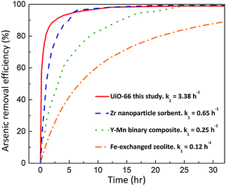
One of the representative examples is UiO-66,11–15 a prototypical Zr-MOF constructed with Zr6O4(OH)4 clusters and terephthalate linkers (1,4-benzenedicarboxylate, BDC).11 Our previous study unveiled that UiO-66 can effectively remove arsenic from water with the highest capacity to date (303 mg g−1) and the widest pH working range (pH 1–10).16 Besides the outstanding thermodynamic performance, the UiO-66 adsorbent also exhibits a rapid uptake profile for arsenic adsorption. Compared to other typical arsenic adsorbents (Zr nanoparticle sorbent, Y–Mn binary composite, and Fe-exchanged zeolite) with particle sizes of several hundred nanometres,17–19 as shown in Fig. 1, the UiO-66 adsorbent with a similar particle size could provide a much faster adsorption rate (at least fivefold faster, in terms of the initial reaction rate constant). This fast kinetics allows an efficient adsorptive separation process to be realized within a micro-space (i.e. very short distance).
 | ||
| Fig. 1 Arsenic adsorption kinetics comparison: UiO-66 and other typical sorbents with the same order-of-magnitude particle size.17–19 | ||
Despite all these preferable performances of UiO-66, in order to be industrially applicable, the powder materials need to be specifically shaped or supported.20,21 This is because in practical applications, dispersed particles could easily leak through the application compartment, resulting in the challenging spent-particles-separation issues and severe safety concerns.22
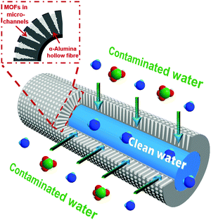
Herein, we developed a MOF/α-alumina composite (composite-1) to take advantage of both the fast kinetics of UiO-66 adsorbents and the novel hollow-fibre geometry of α-alumina for enhanced adsorptive separation, as shown in Fig. 2. The α-alumina was deliberately structured to work as a ceramic hollow fibre providing a plurality of micro-channels for efficient adsorptive separation as well as a thin barrier layer to prevent any loss of active adsorbents. In comparison with traditional packed column beds, composite-1 delivered a more effective adsorption process and consequently a better water decontamination performance.
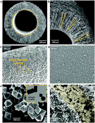
Generally, α-alumina as a raw material is in abundant supply and can provide great resistance to various chemical and thermal conditions. Through controllable spinning and sintering,23,24 we specifically prepared α-alumina in a hollow fibre structure. Its novel geometry with two distinct layers is shown in Fig. 3: one very thin barrier layer (approximately 20 μm of thickness, and with an average pore size around 450 nm as shown in Fig. S1, ESI†) containing a 3D-pore network structure at the lumen, and also one unique layer containing a plurality of conical micro-channels (approximately 500 μm in length, 25 μm in the opening diameter) towards the shell side. These micro-channels not only reduce the mass transfer resistance, giving rise to competitive permeation fluxes,23,25 but also form pockets within which active adsorbents can be readily deposited. As the density of formed micro-channels is quite high, the α-alumina hollow fibre offers a considerable amount of geometric surface area and accessible volume.25
UiO-66 used in this study was synthesized via the typical solvo-thermal method with a minor modification.11,26,27 Its characteristic XRD pattern (see Fig. S2, ESI†) and N2 adsorption–desorption isotherms (see Fig. S3, ESI†) confirm the crystal structure and porosity of this Zr-MOF, respectively.11 As shown in Fig. 3e and f, the UiO-66 crystals were octahedrally shaped with a particle size of around 600 nm.
The formation of composite-1 was achieved via a facile vacuum filtration method (see the ESI†). As shown in Fig. S4 in the ESI,† the vacuum condition was introduced into the lumen of α-alumina hollow fibre, and the water solution carrying MOFs flowed at the shell side with the aid of stirring. Because of the established pressure difference, the water solution would first access and fill the cavities of micro-channels; and then pure water permeated through the thin barrier layer entering the fibre lumen, whereas the MOF crystals could not escape through the barrier layer and had to securely stay within the conical micro-channels owing to the size-exclusion effect (Fig. 2 and 3f). Both FTIR and TGA analyses towards the formed composite suggested that there was only physical attachment between the incorporated MOF crystals and α-alumina matrix (Fig. S9 and S10, ESI†). Moreover, the critical parameters including the particle size of MOFs, MOF concentration in the water solution, magnetic stirrer speed for dispersing MOF crystals in the water solution, as well as duration of the vacuum filtration process were comprehensively investigated (listed in Table S1, ESI†), giving rise to an optimized composite-1 (0.68 mg MOF per gram composite) for the arsenic contaminated water remediation.
Since the arsenic concentration in most contaminated wastewater ranges from 0.1 to 1 ppm,28 the essential arsenic concentration of feed streams was set as 1 ppm. Both the developed composite-1 and equivalent packed columns were investigated in terms of their respective kinetic breakthrough performance for water decontamination.
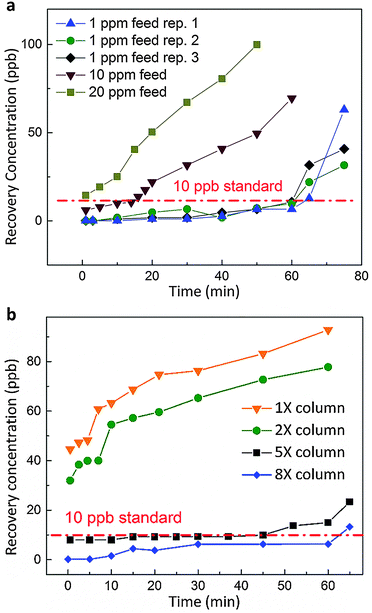
In the case of composite-1, the arsenic contaminated feed stream was introduced into the composite from the shell side to the lumen. In such a manner, the barrier layer at the lumen side could well prevent any active MOF crystals from escaping the composite; and no UiO-66 was detected for the liquid outflow (see the ESI†). When the wastewater stream was transported through the passages of micro-channels, it would contact with the UiO-66 adsorbents; owing to the adsorbents’ fast uptake kinetics, selective adsorption of arsenic from water occurred efficiently within this micro-space. With the optimized operating parameters (listed in Table S2, ESI†), composite-1 was capable of providing clean effluent recovery for 60 minutes, as shown in Fig. 4a. Water from this clean recovery meets the drinkable standards set by both WHO and US-EPA (less than 10 ppb),28 and can be used as potable water supply without any additional post-treatment. Also, the adsorption uptake with regard to the active adsorbent is calculated as ∼23.4 mg g−1 up to breakthrough. These results specified that the probability of feed stream leaking through the micro-channel walls was negligible, as the mass transfer resistance of the walls is orders-of-magnitude larger than that of the micro-channel passages. Furthermore, to obtain an idea of the capability of composite-1, we further increased the arsenic concentration of feed streams to 10 ppm and 20 ppm under the same operating conditions. A much shorter breakthrough time (∼15 min) was noticed for the 10 ppm case, while no clean recovery can be collected if the contaminated feed is as concentrated as 20 ppm.
On the other hand, a comparative study under identical experimental conditions was carried out using packed column beds (see the ESI†). With an equal amount of UiO-66 adsorbents packed into the column (same as the amount loaded in composite-1), the adsorption efficiency was found to be unsatisfactory as shown in Fig. 4b, while the cleanest recovery contained 40 ppb of arsenic. Even if we doubled the amount of UiO-66 in the column media, none of the clean recovery could be collected. On further increasing the quantity of active adsorbents in the column, the column setup started to provide clean recovery; and when 8 times the amount of UiO-66 adsorbent was employed, it provided a similar performance to that of composite-1.
The inferior performance of the packed column beds is associated with the inherent drawbacks like inefficient packing and non-ideal flow.4 Owing to the fact that the packing of adsorbents inside a column is rather random, contaminated streams tend to bypass the adsorbents and directly join the effluent. This phenomenon becomes even more serious when limited amount of adsorbents are used.29 In contrast, composite-1 offers an alternative concept of introducing efficient adsorption within micro-channels. The micro-channels with the conical shape not only ensure a better distribution and more effective control of adsorbent materials, but also form a transport network such that the mass transfer resistance is greatly reduced. Hence, in comparison with the packed column bed, a more ideal flow can be achieved in composite-1, as well as a more efficient contact between contaminants and active adsorbents. As a result, composite-1 provides a much more effective adsorptive separation process using a much smaller amount of active adsorbents, which would lead to considerable cost saving.
Nevertheless, the feasibility of composite-1 in repeated use was restricted, as the arsenic adsorption by UiO-66 was found to be an irreversible sorption process (see the ESI†). Desorption of arsenic from the spent UiO-66 adsorbents was not pragmatic. A novel strategy for developing regenerable MOF adsorbents for arsenic adsorption is still under investigation. Future studies can incorporate these regenerable MOF adsorbents to form a more powerful composite. However, composite-1 in this study resolves a critical industrial problem: generally, for adsorbents to be used in the industry, they must be formed into specific shapes or pellets by combining with a quantity of binder material,30 while the activities, functionalities and effectiveness of the adsorbent become reduced at the end; the incorporation of the active adsorbent into the advanced α-alumina matrix provides a creative approach to use the adsorbent directly and more effectively. Besides, in practical water remediation applications, the barrier layer of α-alumina hollow fibre could further serve as a separation medium to reject suspended solids and micro-organisms.31 Moreover, it is feasible to assemble such functional composites as modules in different scales,23,32 ranging from a small portable water purification unit for household use to a large hybrid adsorption–filtration system in water decontamination plants.
To conclude, a MOF/α-alumina composite with a novel geometry was developed and effectively applied for water decontamination. The composite was formed by depositing UiO-66 adsorbents into the unique micro-channels of a α-alumina hollow fibre through a facile vacuum filtration method. When it was applied for arsenic contaminated water remediation, composite-1 produced the potable water recovery. To achieve a similar performance, the packed column bed required eight times the amount of active UiO-66 adsorbents. Therefore, as a proof of concept, composite-1 has exhibited a promising potential to be applied for industrial water decontamination. Looking forward, based on the specific adsorptive separation applications, various functional composites could be formed. A wide range of adsorbents can be selected and loaded into the α-alumina hollow fibre, of which the micro-channel sizes can be well controlled during fabrication.
This work was supported by the research funding provided by Engineering and Physical Sciences Research Council in the United Kingdom (Grant no. EPSRC, EP/J014974/1). C. Wang gratefully acknowledges the National University of Singapore Graduate School for Integrative Sciences and Engineering scholarship.
Notes and references
- I. Ali, Chem. Rev., 2012, 112, 5073 CrossRef CAS PubMed.
- Y. Yu, C. Wang, X. Guo and J. Paul Chen, J. Colloid Interface Sci., 2015, 441, 113 CrossRef CAS PubMed.
- S.-W. Nam, C. Jung, H. Li, M. Yu, J. R. V. Flora, L. K. Boateng, N. Her, K.-D. Zoh and Y. Yoon, Chemosphere, 2015, 136, 20 CrossRef CAS PubMed.
- A. Dąbrowski, Adv. Colloid Interface Sci., 2001, 93, 135 CrossRef.
- H. Furukawa, K. E. Cordova, M. O'Keeffe and O. M. Yaghi, Science, 2013, 341, 1230444 CrossRef PubMed.
- H. C. Zhou and S. Kitagawa, Chem. Soc. Rev., 2014, 43, 5415 RSC.
- Y.-S. Li, H. Bux, A. Feldhoff, G.-L. Li, W.-S. Yang and J. Caro, Adv. Mater., 2010, 22, 3322 CrossRef CAS PubMed.
- N. A. Khan, Z. Hasan and S. H. Jhung, J. Hazard. Mater., 2013, 244–245, 444 CrossRef CAS PubMed.
- Y.-Y. Fu, C.-X. Yang and X.-P. Yan, Chem. Commun., 2013, 49, 7162 RSC.
- H. Furukawa, F. Gandara, Y. B. Zhang, J. Jiang, W. L. Queen, M. R. Hudson and O. M. Yaghi, J. Am. Chem. Soc., 2014, 136, 4369 CrossRef CAS PubMed.
- J. H. Cavka, S. Jakobsen, U. Olsbye, N. Guillou, C. Lamberti, S. Bordiga and K. P. Lillerud, J. Am. Chem. Soc., 2008, 130, 13850 CrossRef PubMed.
- K. K. Yee, N. Reimer, J. Liu, S. Y. Cheng, S. M. Yiu, J. Weber, N. Stock and Z. Xu, J. Am. Chem. Soc., 2013, 135, 7795 CrossRef CAS PubMed.
- H. B. Shang, C. X. Yang and X. P. Yan, J. Chromatogr. A, 2014, 1357, 165 CrossRef CAS PubMed.
- Z. Hu and D. Zhao, Dalton Trans., 2015, 44, 19018 RSC.
- X. Liu, N. K. Demir, Z. Wu and K. Li, J. Am. Chem. Soc., 2015, 137, 6999 CrossRef CAS PubMed.
- C. Wang, X. Liu, J. P. Chen and K. Li, Sci. Rep., 2015, 5, 16613 CrossRef CAS PubMed.
- Y. Yu, L. Yu and J. P. Chen, Ind. Eng. Chem. Res., 2015, 54, 3000 CrossRef CAS.
- Y. Ma, Y.-M. Zheng and J. P. Chen, J. Colloid Interface Sci., 2011, 354, 785 CrossRef CAS PubMed.
- Z. Li, J.-S. Jean, W.-T. Jiang, P.-H. Chang, C.-J. Chen and L. Liao, J. Hazard. Mater., 2011, 187, 318 CrossRef CAS PubMed.
- D. Wisser, F. M. Wisser, S. Raschke, N. Klein, M. Leistner, J. Grothe, E. Brunner and S. Kaskel, Angew. Chem., Int. Ed., 2015, 54, 12588 CrossRef CAS PubMed.
- S. J. Tesh and T. B. Scott, Adv. Mater., 2014, 26, 6056 CrossRef CAS PubMed.
- J. He, T. S. Siah and J. Paul Chen, Water Res., 2014, 56, 88 CrossRef CAS PubMed.
- M. Lee, Z. Wu, R. Wang and K. Li, J. Membr. Sci., 2014, 461, 39 CrossRef CAS.
- M. Lee, B. Wang and K. Li, J. Membr. Sci., 2016, 503, 48 CrossRef CAS.
- M. Lee, B. Wang, Z. Wu and K. Li, J. Membr. Sci., 2015, 483, 1 CrossRef CAS.
- A. Schaate, P. Roy, A. Godt, J. Lippke, F. Waltz, M. Wiebcke and P. Behrens, Chem. – Eur. J., 2011, 17, 6643 CrossRef CAS PubMed.
- G. Lu, C. Cui, W. Zhang, Y. Liu and F. Huo, Chem. – Asian J., 2013, 8, 69 CrossRef CAS PubMed.
- D. Mohan and C. U. Pittman, Jr., J. Hazard. Mater., 2007, 142, 1 CrossRef CAS PubMed.
- S. Kundu, Water Res., 2004, 38, 3780 CrossRef CAS PubMed.
- C. A. Jeffs, M. W. Smith, C. A. Stone, C. G. Bezzu, K. J. Msayib, N. B. McKeown and S. P. Perera, Microporous Mesoporous Mater., 2013, 170, 105 CrossRef CAS.
- J. He, T. Matsuura and J. P. Chen, J. Membr. Sci., 2014, 452, 433 CrossRef CAS.
- K. Li, Ceramic membranes for separation and reaction, Wiley, 2007 Search PubMed.
Footnote |
| † Electronic supplementary information (ESI) available: Experimental and characterisation details. See DOI: 10.1039/c6cc02317g |
| This journal is © The Royal Society of Chemistry 2016 |


