
 Open Access Article
 This Open Access Article is licensed under a
 Creative Commons Attribution 3.0 Unported Licence
Acoustotaxis – in vitro stimulation in a wound healing assay employing surface acoustic waves
M. E. M.
Stamp†
ab,
M. S.
Brugger†
a,
A.
Wixforth
ab and
C.
Westerhausen
*ab
aChair for Experimental Physics I, University of Augsburg, Universitätsstraße 1, 86159 Augsburg, Germany. E-mail: christoph.westerhausen@gmail.com
bNanosystems Initiative Munich, Schellingstraße 4, 80799 Munich, Germany
First published on 3rd May 2016
Abstract
A novel, ultrasound based approach for the dynamic stimulation and promotion of tissue healing processes employing surface acoustic waves (SAW) on a chip is presented for the example of osteoblast-like SaOs-2 cells. In our investigations, we directly irradiate cells with SAW on a SiO2 covered piezoelectric LiNbO3 substrate. Observing the temporal evolution of cell growth and migration and comparing non-irradiated to irradiated areas on the chip, we find that the SAW–treated cells exhibit a significantly increased migration as compared to the control samples. Apart from quantifying our experimental findings on the cell migration stimulation, we also demonstrate the full bio compatibility and bio functionality of our SAW technique by using LDH assays. We safely exclude parasitic side effects such as a SAW related increased substrate temperature or nutrient flow by thoroughly monitoring the temperature and the flow field using infrared microscopy and micro particle image velocimetry. Our results show that the SAW induced dynamic mechanical and electrical stimulation obviously directly promotes the cell growth. We conclude that this stimulation method offers a powerful platform for future medical treatment, e.g. being implemented as a implantable biochip with wireless extra-corporal power supply to treat deeper tissue.
Introduction
In the medical sciences, we already find a variety of different applications to positively stimulate tissue healing. Of specific interest are techniques which focus on advanced wound treatment, for instance the healing process after an injury or surgery. First being proposed by Knoch and Klug1,2 in the 1960s, the use of therapeutic ultrasound (US) is quite common in health care. This treatment technique shows considerable impact on important processes such as regeneration of hard and soft connective tissue3,4 and provides a documented5 increase of healing rate of up to 40% for bone fractures. Other studies report on a positive influence due to the application of high power ultrasound with a spatial equally distributed intensity of IUS = 30 mW cm−2 (ref. 6) up to 500 mW cm−2.7 On the other hand, an even higher intensity of IUS = 1 W cm−2 obviously leads to the suppression of fracture healing.8 A possible explanation for the observation of the US induced phenomena of enhanced wound healing is an enhanced prostaglandin E2 production,9 a hormone stimulating bone resorption by osteoclasts.10 Further studies prove that US also speeds up the expression osteonectin, osteopontin and fibronectin, all three of them being proteins linked to the functionality and integrity of bone material.11,12 In spite of these obviously beneficial effects, however, US treatment is also subjected to restrictions, as it is linked to also thermal effects. Recent experiments, for example, show a temperature increase in the tissue of about 0.86 K min−1 at a power of 1 W cm−2 and a frequency of 1 MHz during the treatment.13 Therefore, the induced heat for therapeutic treatment can also be harmful and too long exposure times can even lead to necrosis.14 For this reason, US application is often limited to short pulses and low intensities of about 30 mW cm−2.15 These and some other reasons require medical assistance during US treatment sessions as specific knowledge on the correct application is crucial. This fact, but also the high costs of the employed devices often limits the treatments of single sessions or equivalently no longer term US exposure of the injured area and therefore no long term promotion for a fast recovery. It would thus be desirable to have a technique at hand which allows for long term US application without the need of special trained attention during the treatment.Employing Surface Acoustic Waves (SAW), we here propose a novel approach for tissue healing and recovery treatment which has the potential to eliminate some disadvantages of conventional ultrasound treatment methods as described above. SAW have been used since the early nineteennineties as mass products e.g. for filter applications in mobile phones. Roughly fifteen years ago, SAW were employed for e.g. microfluidic manipulation based on the effect of acoustic streaming.16 For an overview we recommend e.g. the review article “Acoustically Driven Programmable Microfluidics for Biological and Chemical Applications”.17 Moreover, SAW also found their biomedical application e.g. for cell manipulation,18 deadhesion under flow19 and on-demand patterning.20 However, so far there are no reports on a SAW-based cell stimulation approach yet. In our study, we apply a continuous SAW beam to a bio-inert substrate to achieve a mechanical stimulation of adherent cells. The SAW we use are so called Rayleigh waves, a distinct mode of SAW propagating mainly at the surface with its energy flow being confined to a layer having a thickness of approximately one wave length.21 To our knowledge, there are no reports on wound healing treatments or medical applications based on SAW technology in literature yet. Here we present this novel technology phenomenologically to the community.
Methods and materials
SAW-chip
The idea behind our ultrasonic promotion of cell migration and growth is to excite SAW directly on the substrate where the cells adhere and proliferate. Our SAW-chip thus consists of the anisotropic piezoelectric material LiNbO3 in Y-cut with the crystal axes rotated around the X-axis by 128° (128° Y-cut). An Interdigital Transducer (IDT), being oriented normal to the crystal X-axis is deposited on top of the substrate by standard lithography. It consists of two multi-finger electrodes (Au, d = 200 nm) with N = 42 finger pairs, as being described first by White and Voltmer22 nearly fifty years ago. The IDT aperture is W = 650 μm and the periodicity of the electrodes is a = 25 μm, which determines the excitation wavelength of the SAW λSAW = 25 μm. Based on λSAW and the substrate SAW velocity cLiNbO3;128°![[thin space (1/6-em)]](https://www.rsc.org/images/entities/char_2009.gif) rot;Y-cut = 3980 m s−1, the resonant frequency fSAW = 159 MHz is obtained for the IDT. To both ensure bio-compatibility and also to protect the metallic structure, the entire chip is covered with a 200 nm thick SiO2 layer, which was deposited by thermal evaporation. Due to the inverse piezoelectric effect, a radio frequency (rf) voltage of power PIN being applied to the IDT results in an oscillating and propagating surface deformation of the chip, the surface acoustic wave. The generated monochromatic Rayleigh SAW in our case consists of both longitudinal and transversal components23 which in principle may interact with the cells on top of the surface. To generate the SAW, we use a conventional rf generator (SML-01, Rhode & Schwarz GmbH, Munich, Germany) and a home built sample holder.
rot;Y-cut = 3980 m s−1, the resonant frequency fSAW = 159 MHz is obtained for the IDT. To both ensure bio-compatibility and also to protect the metallic structure, the entire chip is covered with a 200 nm thick SiO2 layer, which was deposited by thermal evaporation. Due to the inverse piezoelectric effect, a radio frequency (rf) voltage of power PIN being applied to the IDT results in an oscillating and propagating surface deformation of the chip, the surface acoustic wave. The generated monochromatic Rayleigh SAW in our case consists of both longitudinal and transversal components23 which in principle may interact with the cells on top of the surface. To generate the SAW, we use a conventional rf generator (SML-01, Rhode & Schwarz GmbH, Munich, Germany) and a home built sample holder.
Dosimetry
To assess the actual acoustic performance of the chip, we first measure its frequency response with a network analyzer (NWA) (Rhode & Schwarz GmbH & Co. KG., ZVR, Munich, Germany) before we start the experiment. The four pole reflection coefficient S11 for example is a measure for the logarithmic ratio of the amplitude b1 of the reflected rf signal and a1 of the incident rf signal at the IDT. SAW generation at a specific frequency thus results in an increased transmission and hence a decreased reflection. S11 being monitored as a function of the applied frequency can thus be used to determine the resonance frequency and at the same time the transconductance or impedance of the IDT.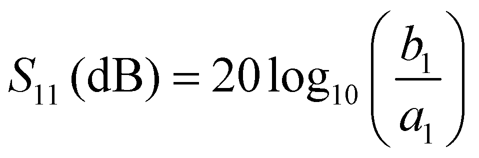
The applied rf power can be given in units of mW as well as dBm. Here it holds:

The IDT used in our experiments is bidirectional, i.e., it excite SAW in both directions at the same time. This fact has to be considered if one calculates the power carried by the SAW from the rf power applied to the transducer. Typically for unloaded chips for the minimal reflection it holds S11 < −20 dB at fSAW. Due to the IDTs bidirectionality, the low reflection values S11 and an insertion loss of the IDT of IL ≈ 3 dB, PSAW can be estimated as  . The acoustic path width is defined by the aperture width W of the IDT. In the experiments all components are matched to an impedance of Z = 50 Ω. As the thickness of the material (e.g. water) covering the SAW-chip is not negligible compared to the SAW wavelengths, the SAW is attenuated through energy absorption resulting in a so called “leaky SAW” with an out-of-plane- and in-plane-attenuation. The out-of-plane-attenuation, dominating the Rayleigh-waves, lead to a calculated SAW-intensity 1/e-decay length in X- and in ⊥X-direction of lCalcop⊥X = 11.5 × λSAW ⊥X = 287.5 μm and lCalcop X = 12.5 × λSAW X = 331 μm.24 Hence, the applied power density can be estimated to
 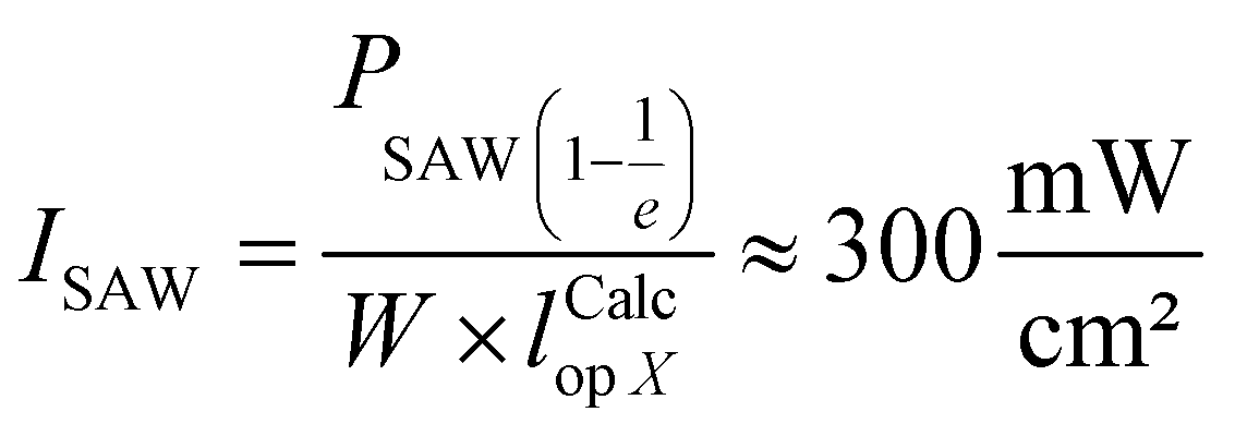 in the case of PSAW = 0 dBm.
Basic settings for the SAW-chip were chosen according to these considerations: (i) the wave length should be comparable to cell dimensions, (ii) by choosing power levels of PIN = 3 dBm − 6 dBm the order of the applied power density is comparable to the one of reported ultra sound treatments and (iii) the acting forces should be far below the threshold necessary for ballistic shift.
To obtain information about the wave amplitude experimentally, we carried out vibrometer measurements using an Ultra High Frequency Vibrometer UHF-120 (Polytec GmbH, Waldbronn, Deutschland) with a Nd:YAG-Laser with a wavelength of λ = 532 nm. The surface of the chip in front of the IDT was scanned during the operation of the loaded as well as the unloaded chip at fSAW = 159 MHz and power levels of PIN = 3 dBm and PIN = 6 dBm in air and in water.
Cells and cell culturing
In all experiments described here, we used the Saos-2 (“sarcoma osteogenic”) human osteosarcoma cell line as described elsewhere.25 The cells were cultured as an adhesive monolayer in Dulbecco's modified Eaglés medium (DMEM) supplemented with 10% fetal bovine serum (FPS Superior), 2% HEPES-buffer (1 M), 1% L-glutamine (200 mM), 1% MEM-Vitamin with 10 mM Na2HPO4 (Biochrom AG, Berlin, Germany) and 0.2% Primocin (InvivoGen, Toulouse, France) in NuncTM cell culture flasks (Thermo Scientific, Massachusetts, USA) in a saturated atmosphere with 5% CO2 at T = 37 °C. Cell passaging followed the standard trypsinization procedure using 1 ml Trypsin/EDTA solution and PBS (w/o Ca2+, w/o Mg2+) (Biochrom AG, Berlin, Germany). By centrifugation and discarding of the supernatant with subsequent resuspension in media we adjusted the cell density to 50000 cells per 70 μl.
Wound healing assay
To study cell migration we used a standard wound-healing assay. After the formation of a confluent cell monolayer, we removed the culture insert (Ibidi ® GmbH, Martinsried, Germany; width 500 μm ± 50 μm) and thus created an artificial ‘wound’. As the cells at the fringe are no longer contact-inhibited, they started moving into the available space resulting in a moving front at constant speed.26The experimental setup
The SAW-chip as described above was mounted and contacted on a sample holder providing the rf lines to the generator. On top of the SAW chip, a small (V = 1.2 ml) polydimethylsiloxane (PDMS) chamber housed the cells and the buffer (Sylgard 184 Silicone Elastomer, Dow corning, Germany; m/m ratio 10:1). To avoid leakage between chamber and SAW-chip the contact surfaces were coated with highly viscous silicon grease (Baysilone-Paste, GE Bayer Silicones, Leverkusen, Germany). We autoclaved the setup at T = 134 °C prior to each experiment and placed the sterile culture-insert parallel to the IDT aperture in a distance of d = 50 μm. In each culture insert chamber, we seeded 70 μl of the cell suspension containing 50000 cells before we filled the whole PDMS-chamber entirely with nutritive fluid and covered it with a glass plate to prevent contamination (see Fig. 1). Subsequently, we let the cells grew to confluence for 48 hours. Then, by removing the culture insert an artificial wound was created, the cell layers were rinsed with PBS and the PDMS-chamber refilled with fresh media. While being connected to the rf generator and positioned on the motorized microscope stage (Axiovert 200, Zeiss, Göttingen, Germany), the sample was incubated. We employed an Ibidi heating system chamber (HT 200, Ibidi, Martinsried, Germany) with a gas incubation system (the Brick, Live Image Services, Basel, Switzerland) in saturated atmosphere with 5% CO2 at T = 37 °C. To monitor the wound healing process, phase contrast microscope images of the ‘wound’ were taken every 5 min for 72 h using a 10× objective lens.
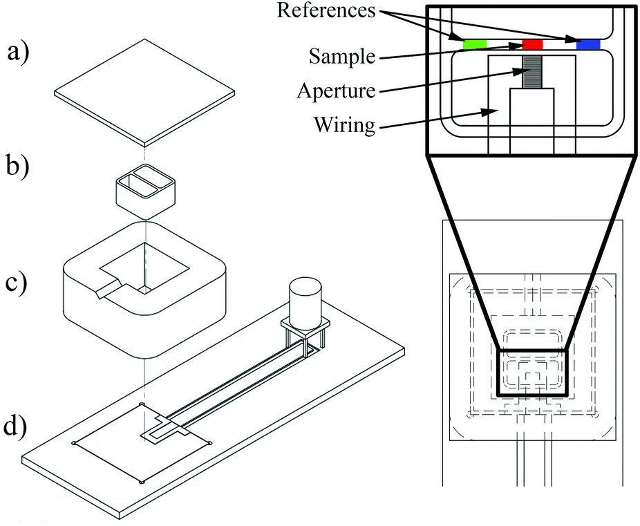 | ||
| Fig. 1 Technical drawing of the experimental setup. Left: Exploded-view describing all major constituents with (a) cover slip, (b) culture insert, (c) PDMS-chamber and (d) sample holder with SAW-Chip. Right: Top-view displaying the culture insert positioning relative to the IDT. The enlarged figure describes the treated area in the sound path “aperture” (red) and the internal references (green and blue). | ||
Cytotoxic analysis
To investigate cell damaging effects caused by the SAW-treatment, we made use of a lactate dehydrogenase (LDH) release assay (Cytotoxicity Detection KitPlus, Roche Diagnostics, Mannheim, Germany). After exposing the cells to a SAW as described above, the LDH activity of the sample's cell-free supernatant was determined by measuring the optical absorption a λ = 492 nm in a plate reader (Infinite ® 200 Pro series, Tecan Group Ltd, Männedorf, Switzerland).27Results and discussion
Effect of SAW treatment on cell migration
The micrographs in Fig. 2 show the wound healing process at different times after removing the culture insert. A visual comparison of the treated and untreated samples as well as the previously described cytotoxic analysis verify that no evident apoptosis is found. The LDH activity of the SAW-treated samples corresponds to the reference and conventionally cultivated cells, again indicating no detrimental effect on the cells. Both, treated and untreated cells show a relative LDH concentration of 10 ± 3% compared to the high control 24 h after start of the experiment.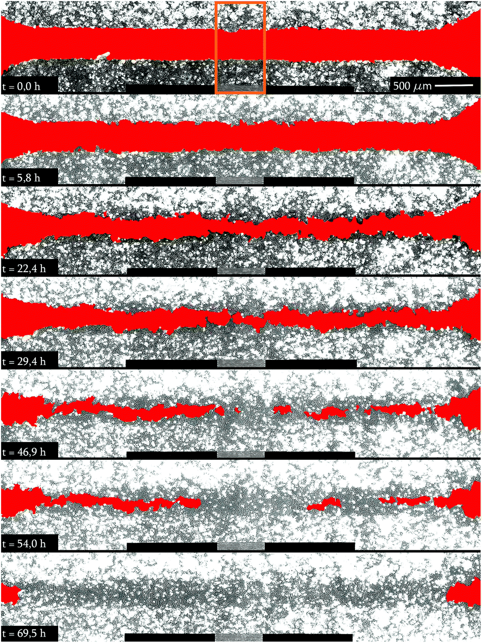 | ||
| Fig. 2 Graphical evaluation of a SAW-treated sample (batch # 3) over time. The position of the SAW path (aperture) is indicated by the rectangle in the upper panel. The contact areas (no SAW) are depicted as solid black lines at the bottom of the panels. The images at t = 46.9 h and t = 54.0 h clearly show an increased cell migration at the location of the aperture. At t = 69.5 h, the whole area is colonized apart from the very outer edges outside of the assay. | ||
As the width of the sound path is strictly determined by the IDT aperture, only adherent cells in this area are directly exposed to the SAW.28 This area is called aperture in the following. As the cells in the remaining area next to the contacts (see picture in Fig. 3) and outside the SAW path are not directly exposed to the SAW, they serve as a built-in, internal, natural reference to compare cell growth behaviour under truly identical conditions (i.e. viability, nutrient supply, temperature, cell density, etc.) on the same chip.
 | ||
| Fig. 3 Determined cell-free area as function of time. The cell free area F(t) is normalized to the initial value F(0). The insert displays a microscope image showing left and right areas as internal reference. The average total migration velocity at the aperture is 3.8 × 1.2 μm h−1, while the references only reaches values of 3.1 × 1.4 μm h−1. | ||
To evaluate the scientific content of the taken images, they were analyzed in terms of the cell-free area as a function of time. This time dependent shrinking area F(t) is normalized to the cell-free area F(0) at the beginning of the experiment. In Fig. 3, we depict the result for F(t)/F(0) and a typical wound healing experiment. As the cells spread at a constant speed, F(t) decreases linearly after a short dwell time after the start of the experiment. Depending on the position of the cell layer with respect of the position of the sound path, we observe different slopes of this linear dependence where the SAW exposed cells exhibit the steepest slope.
Fig. 4 displays the averaged value of these slopes, both for the SAW exposed (aperture) cells as well as for the on-chip references (left, right). We denote this average slope values “surface area migration rate Amig” for both, the internal reference as well as the aperture at different power levels (PIN = 3 dBm and 6 dBm). Clearly, Amig is higher for SAW treated cells as compared to the reference. We thus feel safe to claim significantly increased healing rate in the sound path of the SAW. For this, the ratios of Amig in the aperture region and in the internal reference region are shown in Fig. 5. Independent of the applied power in the experiment, we observe an average increase in the ratio Amig, Aperture/Amig, Reference of about 15.2% ± 1.7%. Here the 90%-confidence intervals of Amig, Aperture/Amig, Reference for the PIN = 3dBm and 6 dBm are [1.02;1.25] respectively [1.06;1.27]. In no single experiment the migration velocity of the reference was higher than the one of the treated sample.
 | ||
| Fig. 4 Comparison of the surface area migration rate Amig of aperture and internal reference at different power level PIN. Amig of the treated samples is always higher than the untreated samples. | ||
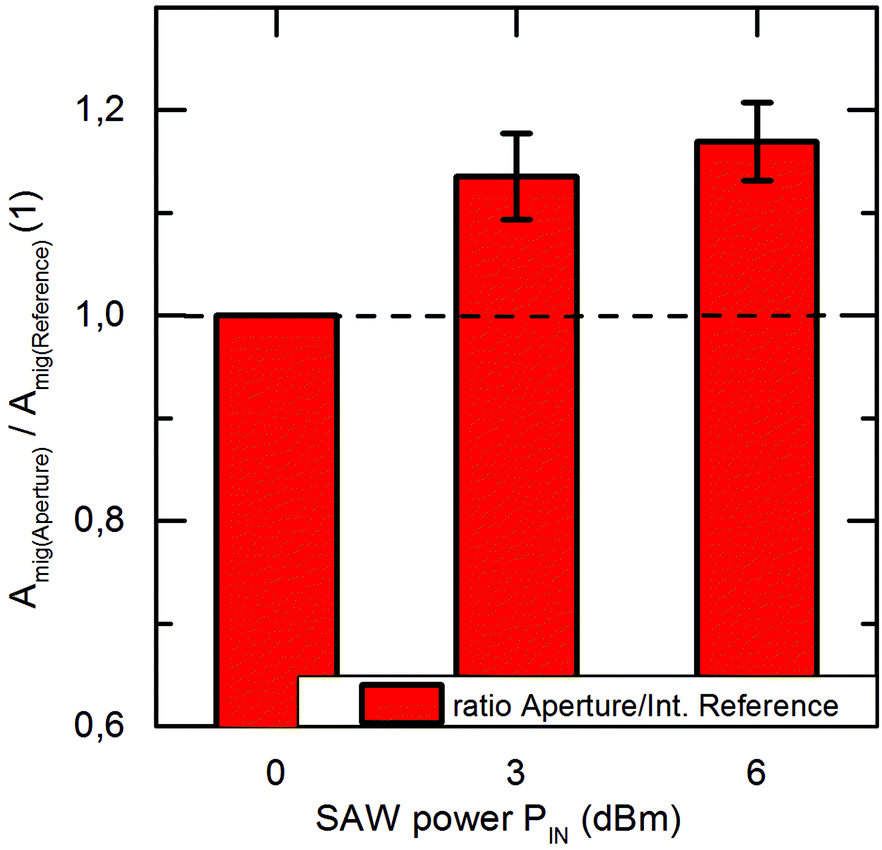 | ||
| Fig. 5 Ratio of the surface area rate of treated and untreated samples. The mean values of the series 1 and 2 at PIN = 3 dBm and series 3–6 at PIN = 6 dBm are plotted. Both power levels feature an averaged increase of their surface area rate of up to 15.2% ± 1.7%. | ||
To compare the migration speed of the two moving cell fronts in the aperture region independently, we separate the cell free aperture region into two identical sectors and analyzed Amig of each section (‘up’ and ‘down’) separately.
Surprisingly, we find that both cell fronts apparently migrate at the same speed, as shown in Fig. 6.
 | ||
| Fig. 6 Comparative analysis of migration velocities of the two migrating cell fronts in the aperture region. Depending on the initial conditions (cell cycle, cell activity and concentration) different absolute values have been obtained. The values are distributed around the angle bisector demonstrating the correlation between the surface area migration rate of both cell fronts. | ||
Here, we plot the migration speeds of each cell front against each other and find a clear 1:1 correspondence as being indicated by the 45° slope of the data points.
Taking a closer look at the trajectories of single cell migration (Fig. 7), we cannot detect a preferred direction of motion apart from the well-known migration into the cell free area. In particular, cells being located in the sound path do not escape the area neither are cells from outside migrating inwards.
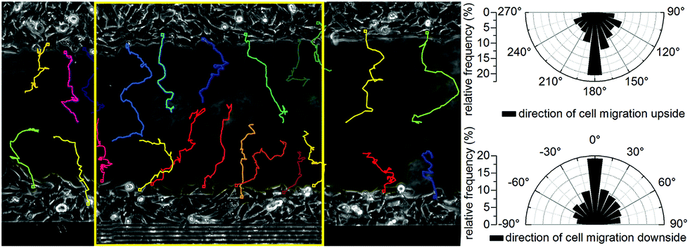 | ||
| Fig. 7 Left: Micrograph of the cell free area in front of and beside the IDT at the start of the experiment. Right: Relative frequency of the cell migration direction inside the sound path. The colored lines indicate the trajectories of the cells during the measurement. The rectangular field describes the sound path. The cells migrate directed into the cell free area, as shown in this microscope image and the polar diagrams. There is no noticeable tendency of a migration out of the sound path. | ||
Comparing the findings at the reference region (Fig. 8) with the data shown in Fig. 7 (aperture) indicates no significant difference. The migration direction seems thus to be dominated by the cell layers anisotropy alone and causes a preferred migration into the cell free area.
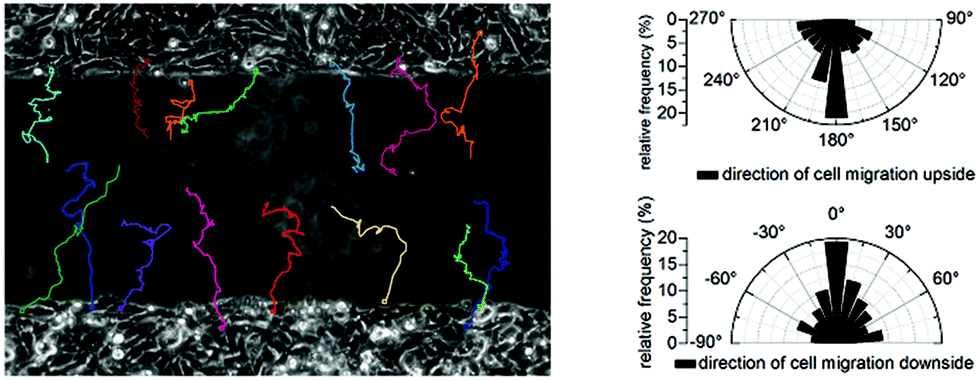 | ||
| Fig. 8 Left: Micrograph with trajectories of the cell free area in the right internal reference region at the start of the experiment. Right: Relative frequency of the cell migration direction. | ||
So far, we proof that cells, exposed to SAW show an increased wound healing effect in vitro of 15.2% ± 1.7%. With this method, the surface coverage rate of the cell front is monitored. Thus, there is no possibility to distinguish between increased proliferation and migration. However, in the following we further elucidate the mechanism of this stimulation. Therefore, we first exclude several side effects possibly induced by the SAW treatment.
Ballistic shift
It is well known that a SAW induces acoustic streaming, when coupling into a liquid at the interface.29 This microfluidic flow can cause a mechanical deflection or even movement of the adherent cells in the vicinity of the IDT. To characterize the flow profile and velocities in the medium, we used particle image velocimetry. As shown in Fig. 9, the flow profile 30 μm above the substrates surface is directed towards the IDT. As a jet of the liquid is streaming upwards under the Rayleigh angle, close to the surface liquid is drawn towards the IDT. With a maximum velocity of ν = 25 μm s−1 we reach a maximal dynamic pressure q ofwith the density of water ρ. As significant change in cell structure and elongation under flow conditions only occurs above 0.5–1 Pa,30 this effect can be neglected here.

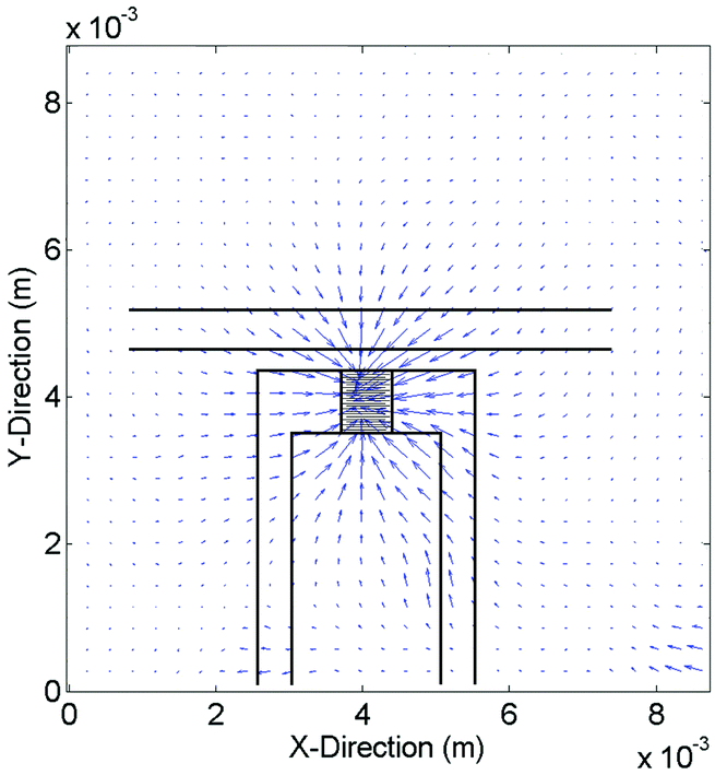 | ||
| Fig. 9 Velocity profile 30 μm above the substrate surface in media. Analyzed maximal speeds reaching up to ν = 25 μm s−1. | ||
Enhanced nutrient supply due to agitation
The nutrient concentration distribution in resting media is driven by diffusion. Caused by the acoustic streaming, the cell surrounding media is stirred. Therefore, the local nutrient supply can be increased. Although it is already shown that enhanced nutrient supply does not increase cell growth in vitro,31 we study wound healing with and without agitation in control experiments, using the IDT as a pump. Therefore, we placed the IDT parallel to the gap but at the outer edge of the cell layer (PIN = 6 dBm). In these experiments, we find that Amig is the same with and without nutrient agitation (data not shown). Hence, we exclude nutrient supply as a main cause for enhanced wound healing.Heat generation
The creation of a SAW is subject to various losses.32 To gain insight into a possible SAW related substrate heating, we measured the temperature rise of the used chip under unloaded and water loaded conditions at RT via infrared microscopy. In the range PIN = 100 mW the temperature increase, as being displayed in Fig. 10 is a linear function of power for loaded (ΔT/ΔP = 37 mK mW−1) as well as unloaded conditions (ΔT/ΔP = 80 mK mW−1). For the adherent cells in the vicinity of the IDT this results in a maximal temperature increase of ΔT ≤ 0.32 K (PIN = 6 dBm respectively 4 mW). As in vivo the afebrile temperature already varies around 1 K, we can exclude local heat as the main beneficial effect.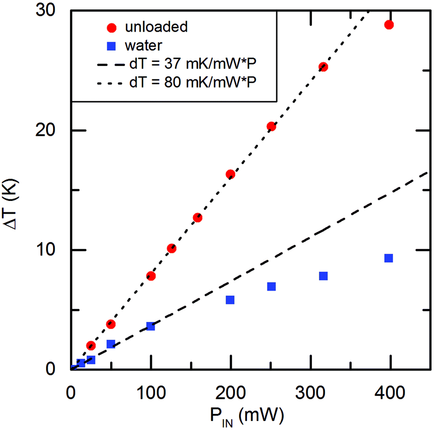 | ||
| Fig. 10 Surface temperature increase as function of applied power PIN under loaded and unloaded conditions. | ||
Mechanical stimulation
Propagating SAW consist of both a mechanical and an electrical component. The applied rf power PIN divides into these components. By employing vibrometer experiments, the SAW amplitude uz can be measured. We find that the maximal amplitude uz for a power level of PIN = 6 dBm is uz = 0.42 nm, as shown in Fig. 11. Whilst the SAW on the unloaded substrate propagates almost undamped along the surface, significant viscous attenuation occurs on the loaded sample as expected. The determined 1/e-decay length l = 243 μm under loaded conditions is in very good agreement with calculated values.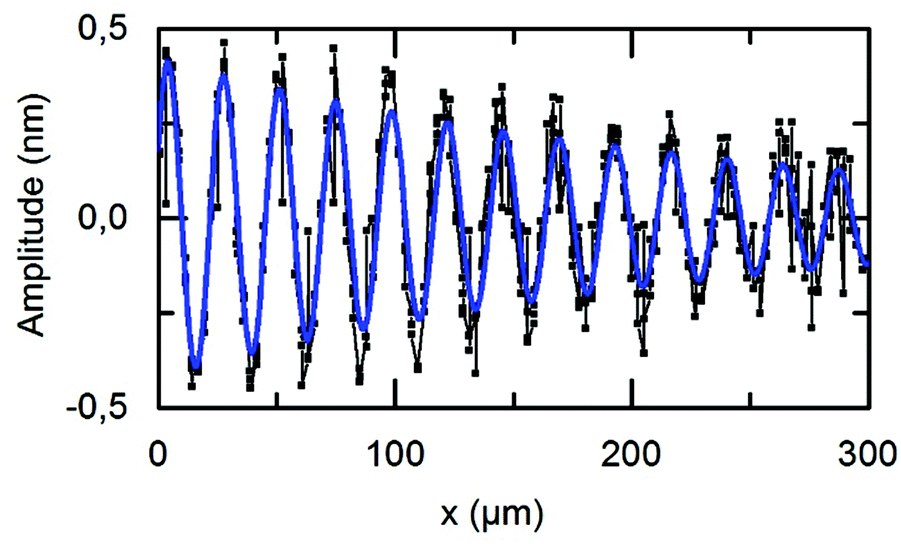 | ||
| Fig. 11 Amplitude of a water damped SAW at PIN = 6 dBm showing a 1/e-decay length l = 243 μm. | ||
In literature, the stimulation mechanism of US therapy is assumed to be a mechanical one. This leads to high calcium uptakes33 and calcium plays an important role, e.g. in cellular communication.34 Furthermore, it has been reported that the proliferation increases between 35%–52% and the synthesis of collagen and non-collagen proteins increases up to 112%. In addition, US was able to rise the production of angiogenese supporting cytokines (Interleukin IL-1β, IL-6, IL-8).35 Based on our results, we thus suspect that a SAW treatment, similar to US treatment interferes with the regular functions of the cell and the cell membrane due to its mechanical effect. The precise nature of this interaction requires separate extensive studies in the field of mechanotransduction, like investigation of the response of cell in terms of gene expression and adaption of the cytoskeleton. For other mechanic stimuli it has been shown that, depending on external forces actin-myosin stress fibres are formed, which can be later examined using fluorescence microscopy.36
Electrical stimulation
Apart from the mechanical stimulation, several clinical studies revealed that also electric fields can be responsible for cell stimulation, as well. Increased healing of fractures was for example achieved37,38 through the use of small, low frequency (10–90 Hz) electromagnetic fields. Also radio frequency fields (27 MHz) can benefit anti-inflammation and healing supporting reactions in tissue.39 Due to the rf signal applied to the IDT on our chip, an electric field in the order of several kV cm−1 is generated directly at the chip surface, where the cells adhere. In order to estimate the SAW surface potential from the amplitude uz, theoretical considerations are done. In the model described by Datta40 in 1986, the amplitude uz is inherently linked to the surface potential through uz = ϕ × cz where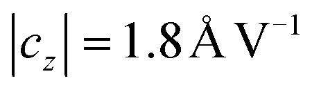 characterizes the relative displacement in z-direction. Combined with the data from Fig. 11 this results in a surface potential of ϕ = 2.3 V for PIN = 6 dBm. To further elucidate the role of the electric field, we presently develop several types of SAW-chips for wound healing assays involving conductive layers on the substrate to shield the E-field, as for electric field treated cell culture production of reactive oxide stress has been shown to increase cell migration.41 Hence, the exciting question remains, whether the mechanism of the here presented stimulation method is of pure mechanical nature or purely of electrical nature or a combination of both.
Conclusion and outlook
In this manuscript, we present a novel and unconventional method for positive tissue stimulation. We employ surface acoustic waves and apply them to Saos-2 cells in a wound healing assay. Adherent cells located in the sound path of the SAW indeed exhibit positive effects in their migration behavior. First studies revealed a successful implementation of acoustic vibrations to an artificial wound leading to a higher healing rate of up to 17% in vitro. We attribute the stimulation to a direct mechanical or electrical stimulation by the SAW.The next challenge is to identify the involved biochemical processes. Therefore, future studies will focus not only on cell ensembles but also on single cells, their response, in terms of cell activation, changes of the cytoskeleton, production of reactive oxide stress and biomarker expression. We envision to successfully control the migration velocity as well as its direction employing low intensity amplitude modulated SAW. This new method and its effect could be a form of ‘Acoustotaxis’. With our presented method of cell stimulation, we are also moving along the lines of a new approach for tissue engineering. The cost-efficient, easy to handle and local deployable technology opens a large range of possible applications, e.g. for fast recovery after injury or surgery. As a long term goal, we envision an implantable biochip with wireless extra-corporal power supply, making deeper tissue accessible via induction.42 Direct sputtering of piezoelectric materials such as ZnO as well as electrodes on arbitrary biocompatible flexible or rigid substrates for i.e. hip joint replacement43–45 could allow treatment of damaged tissue directly after surgery for fast recovery. As the rf technology employed is standard in mass products, like mobile phones the chip as well as the peripheral equipment can be easily miniaturized. Finally, a wide range of physiological add-ons becomes possible. If, e.g., therapeutic hyperthermia is desired, a local temperature increase at the substrate surface can be provoked by using specific loss mechanisms such as interaction of thermally induced elastic waves, scattering at crystal defects or impurities and cracks.32,46
Acknowledgements
The authors thank the “Deutsche Forschungsgemeinschaft (DFG)” for the financial support of this work by means of the “Erkenntnistransferprojekt Antibakterielle und abriebarme Beschichtung von Gleitflächen in orthopädischen Implantaten”. We thank Christian Huck (TDK-EPC) for IR-microscopy, Alexander T. Bauer for fruitful discussions and Sidonie Lieber for technical assistance. Furthermore, MEMS thanks the Bayerische Forschungsallianz for funding and Dr Julien Reboud and Dr Rab Wilson (University of Glasgow) for technical assistance with vibrometer measurements. CW likes to acknowledge funding by Nanosystems Initiative Munich (NIM) via their Seed Funding Program.Notes and references
- H. G. Knoch, Schriften der Med. Akad. Dresden, 1967, 6, 81–87 Search PubMed.
- W. Klug, W. G. Franke and H. G. Knoch, Eur. J. Nucl. Med., 1986, 11, 494–497 CrossRef CAS PubMed.
- T. K. Kristiansen, J. P. Ryaby, J. McCabe, J. J. Frey and L. R. Roe, J. Bone Jt. Surg., 1997, 79, 961–973 CAS.
- A. Binder, G. Hodge, A. M. Greenwood, B. L. Hazleman and D. P. Page Thomas, Br. Med. J., 1985, 290, 512–514 CrossRef CAS PubMed.
- J. D. Heckman, J. P. Ryaby, J. McCabe, J. J. Frey and R. F. Kilcoyne, J. Bone Jt. Surg., 1994, 76, 26–34 CAS.
- A. A. Pilla, M. A. Mont, P. R. Nasser, S. A. Khan, M. Figueiredo, J. J. Kaufman and R. S. Siffert, J. Orthop. Trauma, 1990, 4, 246–253 CrossRef CAS PubMed.
- M. Dyson and M. Brookes, Ultrasound Med. Biol., 1982, 61–66 Search PubMed.
- C.-L. Tsai, W. H. Chang and T.-K. Liu, Chin. J. Physiol., 1992, 35, 21–26 CAS.
- T. Kokubu, N. Matsui, H. Fujioka, M. Tsunoda and K. Mizuno, Biochem. Biophys. Res. Commun., 1999, 256, 284–287 CrossRef CAS PubMed.
- A. H. Tashjian, J. E. F. Voelkel, L. Levine and P. Goldhaber, J. Exp. Med., 1972, 136, 1329–1343 CrossRef CAS PubMed.
- T. Kreis and R. Vale, Guidebook to the extracellular matrix, anchor, and adhesion proteins, Oxford University Press, New York, 2nd edn, 1999 Search PubMed.
- J. Harle, V. Salih, F. Mayia, J. C. Knowles and I. Olsen, Ultrasound Med. Biol., 2001, 27, 579–586 CrossRef CAS PubMed.
- R. Williams, Physiotherapy, 1987, 73, 113–116 Search PubMed.
- N. B. Smith, J. M. Temkin, F. Shapiro and K. Hynynen, Ultrasound Med. Biol., 2001, 27, 1427–1433 CrossRef CAS PubMed.
- D. L. Miller, N. B. Smith, M. R. Bailey, G. J. Czarnota, K. Hynynen and I. R. S. Makin, J. Ultrasound Med., 2012, 31, 623–634 Search PubMed.
- A. Rathgeber, C. Strobl, H.-J. Kutschera and A. Wixforth, 2001, arXiv:physics/0104079.
- A. Wixforth, J. Assoc. Lab. Autom., 2006, 11, 399–405 CrossRef CAS.
- J. Shi, D. Ahmed, X. Mao, S.-C. S. Lin, A. Lawit and T. J. Huang, Lab Chip, 2009, 9, 2890–2895 RSC.
- A. Hartmann, M. Stamp, R. Kmeth, S. Buchegger, B. Stritzker, B. Saldamli, R. Burgkart, M. F. Schneider and A. Wixforth, Lab Chip, 2014, 14, 542–546 RSC.
- X. Ding, S.-C. S. Lin, B. Kiraly, H. Yue, S. Li, I.-K. Chiang, J. Shi, S. J. Benkovic and T. J. Huang, Proc. Natl. Acad. Sci. U. S. A., 2012, 109, 11105–11109 CrossRef CAS PubMed.
- L. Rayleigh and J. W. Strutt, Proc. London Math. Soc., 1885, 17, 4–11 CrossRef.
- R. M. White and F. W. Voltmer, Appl. Phys. Lett., 1965, 7, 314–316 CrossRef.
- D. Morgan, Surface Acoustic Wave Filters, Academic Press, London, 2nd edn, 2007 Search PubMed.
- K. Dransfeld and E. Salzmann, Phys. Acoust., 2012, 7, 219–272 Search PubMed.
- J. Fogh and G. Trempe, in Human tumor cells in vitro, Springer, 1975, pp. 115–159 Search PubMed.
- P. K. Maini, D. L. S. McElwain and D. Leavesley, Appl. Math. Lett., 2004, 17, 575–580 CrossRef.
- R. L. Science, Cytotoxicity Detection Kit (LDH), 2011, vol. 6 Search PubMed.
- T. Frommelt, Dissertation, University of Augsburg, Augsburg, 2007.
- A. Wixforth, Superlattices Microstruct., 2003, 33, 389–396 CrossRef CAS.
- C. F. Dewey, S. R. Bussolari, M. A. Gimbrone and P. F. Davies, J. Biomech. Eng., 1981, 103, 177–185 CrossRef PubMed.
- A. S. Goldstein, T. M. Juarez, C. D. Helmke, M. C. Gustin and A. G. Mikos, Biomaterials, 2001, 22, 1279–1288 CrossRef CAS PubMed.
- A. J. Slobodnik Jr., P. H. Carr and A. J. Budreau, J. Appl. Phys., 1970, 41, 4380–4387 CrossRef.
- A. J. Mortimer and M. Dyson, Ultrasound Med. Biol., 1988, 14, 499–506 CrossRef CAS PubMed.
- C. M. Weaver and R. P. Heaney, Calcium in Human Health, Humana Press, Totowa, New Jersey, 2006 Search PubMed.
- N. Doan, P. Reher, S. Meghji and M. Harris, J. Oral Maxillofac. Surg., 1999, 57, 409–419 CrossRef CAS PubMed.
- E. K. Paluch, C. M. Nelson, N. Biais, B. Fabry, J. Moeller, B. L. Pruitt, C. Wollnik, G. Kudryasheva, F. Rehfeldt and W. Federle, BMC Biol., 2015, 13, 47 CrossRef PubMed.
- R. A. Luben, C. D. Cain, M. C.-Y. Chen, D. M. Rosen and W. R. Adey, Proc. Natl. Acad. Sci. U. S. A., 1982, 79, 4180–4184 CrossRef CAS.
- C. A. Bassett, R. J. Pawluk and A. A. Pilla, Science, 1974, 184, 575–577 CAS.
- D. Foley-Nolan, K. Moore, M. Codd, C. Barry, P. O'Connor and R. J. Coughlan, Scand. J. Rehabil. Med., 1992, 24, 51–59 CAS.
- S. Datta, Surface acoustic wave devices, Prentice Hall, 1986 Search PubMed.
- K.-Y. Lo, S.-Y. Wu and Y.-S. Sun, Microfluid. Nanofluidics, 2016, 20, 15 CrossRef.
- A. Polh, IEEE Trans. Ultrason. Ferroelectr. Freq. Control, 2000, 47, 317–332 CrossRef CAS PubMed.
- B. T. Khuri-Yakub, G. S. Kino and P. Galle, J. Appl. Phys., 1975, 46, 3266–3272 CrossRef CAS.
- N. W. Emanetoglu, C. Gorla, Y. Liu, S. Liang and Y. Lu, Mater. Sci. Semicond. Process., 1999, 2, 247–252 CrossRef CAS.
- C. K. Lau, S. K. Tiku and K. M. Lakin, J. Electrochem. Soc., 1980, 127, 1843–1847 CrossRef CAS.
- S. Jyomura, J. Appl. Phys., 1981, 52, 4472–4478 CrossRef CAS.
Footnote |
| † Authors contributed equally. |
| This journal is © The Royal Society of Chemistry 2016 |