
 Open Access Article
 This Open Access Article is licensed under a Creative Commons Attribution-Non Commercial 3.0 Unported Licence
Glass fibre paper-based test strips for sensitive SERS sensing†
Axel
Bolz
a,
Ulrich
Panne
ab,
Knut
Rurack
a and
Merwe
Buurman
*a
aBAM Federal Institute for Materials Research and Testing, Richard-Willstätter-Straße 11, 12489 Berlin, Germany. E-mail: merwe.buurman@bam.de
bDepartment of Chemistry, Humboldt University Berlin, Brook-Taylor-Straße 2, 12489 Berlin, Germany
First published on 12th January 2016
Abstract
We present paper-based test strips for chemical sensing with surface enhanced Raman scattering as detection method. The test strips are prepared on glass fibre paper with silver nanoparticles and a spray method with an airbrush spray setup as a low cost fabrication approach. The properties of the test strips are investigated with three classical Raman analytes rhodamine 6G, 4-aminothiophenol and adenine and optimized for a good reproducibility of the intensity measurements. All test analytes can be identified at low concentrations. For adenine, a concentration series from 10−4 M to 10−8 M is measured and the calibration data can be fitted and evaluated with a Langmuir isotherm model. The optimized test strips are applied for the identification of two antibiotics enoxacin and enrofloxacin.
Introduction
Surface enhanced Raman scattering (SERS) as an extension of the classical Raman spectroscopy is currently one of the most popular label-free spectroscopic techniques exploited for applications in (bio)analytical chemistry in which rapid and non-destructive measurements are required.1,2 The advantage of SERS compared to normal Raman spectroscopy is the enhancement of the Raman signal of the sample molecules, which allows the measurement of Raman spectra of analytes in concentration ranges as low as the single molecule level.3–5 After the first observation of the SERS effect by Fleischmann et al.,6 different theories were developed for its explanation.7,8 Currently, it is generally accepted that the enhancement of the Raman signal is a combination of an electromagnetic and a chemical effect.2,9 A large variety of nanomaterials can be used as SERS substrates, e.g., nanoparticles10 or hybrid materials11,12 in solution, polymers with embedded nanoparticles,13 or solid substrates prepared for instance by lithography.14 However, most SERS substrates are not applicable in a wide range of commercial applications as they do not have the desired properties or are too expensive.15 Therefore, the investigation of paper-based SERS substrates has started already as early as in 1984.16 Paper-based SERS substrates are cheap, easy to handle and simple to prepare. In the last ten years, the focus lay on cellulose paper prepared with different nanoparticles and by different deposition methods.17–29In this contribution, we report on a glass fibre paper-based SERS substrate on which nanoparticles (NPs) were deposited with a new spray setup. These test strips were investigated in terms of preparation procedures. The most frequently used method for the deposition of NPs on paper is printing of NP solutions.17,18,22,23,30,31 For the coating of large paper areas, spraying of the NP solutions can also be used.25 In this article, we use a spray setup utilizing an airbrush to obtain a reproducible NP coating on paper. Besides conventional cellulose, we turned our attention to glass fibre paper which has so far only scarcely been used as substrate16,30,32,33 yet has been reported to show improved performance in SERS applications compared with cellulose paper.16 The airbrush-based deposition method was tested with strips made from glass fibre and cellulose papers on two Raman setups and the best performing combination was finally employed for the determination of the two antibiotics enoxacin and enrofloxacin in liquid samples. Analysis of these fluoroquinolone antibiotics is relevant for water and food monitoring.34 Enrofloxacin is a drug used in livestock farming and is listed with a maximum residue level of 0.1 ppm in meat by various health/food organizations.34–37 Enoxacin is a broad-spectrum antibiotic for humans.38 To assess the dynamic range of the method, a concentration series of adenine in the range of 10−4 M to 10−8 M was measured. The received data from the concentration series can be fitted by a Langmuir isotherm18,31,39–41 which was used for data evaluation.
Experimental
Materials
Silver nitrate (99.8%, AppliChem), sodium borohydride (≥96%, AppliChem), trisodium citrate (≥98%, Sigma-Aldrich), hydrogen tetrachloroaurate(III) trihydrate (≥99%, Sigma-Aldrich), sodium chloride (≥99%, Th. Geyer), adenine (≥98%, Carl Roth), 4-aminothiophenol (96%, Acros Organics) and rhodamine 6G (98%, Acros Organics) were used as received. Enoxacin and enrofloxacin of highest available purity were a gift from a collaborator. The cellulose filter paper was obtained from Munktell (Grade 390) and the glass fibre filter paper from Ahlstrom (Grade 8964). In all applications, deionized water (Millipore: Milli-Q® 2 grade; 18.2 MΩ cm−1) was used as solvent.Synthesis of nanoparticles (NPs)
Silver nanoparticles (AgNP-I) were synthesized by reduction of silver nitrate with sodium borohydride.42 330 mL of a mixture of silver nitrate (c = 1.1 × 10⁻⁴ M) and trisodium citrate (c = 2.05 × 10⁻³ M) was prepared before 9 mL of sodium borohydride solution (c = 5 × 10⁻³ M) were added rapidly at room temperature under stirring. The colour of the solution immediately changed from colourless to yellow.A second batch of silver nanoparticles (AgNP-II) was prepared by reduction of silver nitrate with sodium citrate.10 300 mL silver nitrate solution (c = 1 × 10⁻³ M) were heated up to boiling under stirring prior to addition of 6 mL of sodium citrate solution (c = 3.9 × 10⁻² M). The solution was then kept for one hour under reflux and stirring and concentrated to 220 mL. The final NP suspension was cooled to room temperature and has a brownish grey colour.
Gold nanoparticles (AuNP) were produced according to a method established by Lee and Meisel.10 Into 300 mL of boiling water, 9 mL hydrogen tetrachloroaurate(III) solution (c = 2.56 × 10⁻² M) and 12 mL sodium citrate solution (c = 3.9 × 10⁻² M) were subsequently added. The solution was stirred for one hour under reflux and turned into a dark red NP solution, which was cooled down to room temperature.
Characterization of NPs and test strips
UV/VIS measurements were realized with a V-650 UV-VIS Spectrophotometer from JASCO. The NP solutions were measured in transmission mode and the papers were measured in reflection mode with an integrating sphere and the uncoated paper as reference. The sizes and the size distributions of the NPs were determined from TEM measurements. The TEM images were obtained with a TECNAI G220 S-TWIN, FEI with accelerating voltage of 200 kV, LaB6-cathode and the images recorded in bright field mode. SEM images were captured with a XL30ESM, FEI in the low vacuum mode (33.3 Pa) and with EDX detector, EDAX. Information on the characterization of the NPs can be found in the ESI (Fig. S1 and S2†).Preparation of test strips
The coating of the papers with nanoparticles was achieved by two different deposition methods. First, test strips were prepared by dropping NP solution with an Eppendorf pipette directly onto the paper and letting it dry. The used NP solution was 15-fold concentrated by centrifugation. Three drops (34 μL each) of the concentrated NP solution were dropped on paper strips of 1 cm2 size (volume of synthesized NP solution per area = 1.53 mL cm−2).Second, a spray method was used for depositing the prepared nanoparticle solutions onto the strips. An airbrush (Double Action Airbrush-Pistol AB 200 cone-Ø 0.2 mm) was used for spraying with a nitrogen gas flow (99.999%, Linde) at a pressure of 250 kPa and a deposition rate of 3.6 × 10⁻⁴ mL s−1 of the NP solution. Fig. 1 shows the scheme of the spray setup. The airbrush is fixed perpendicular to the paper and in the middle of two linear stages (x and y direction). The linear stages are operated with a drift rate of 3 × 10⁻⁴ m s−1 in y direction and with three or five circles per y line and ten lines per paper strip in x direction (volume of synthesized NP solution per area = 1.50 mL cm−2). A LabVIEW program controls the linear stages.
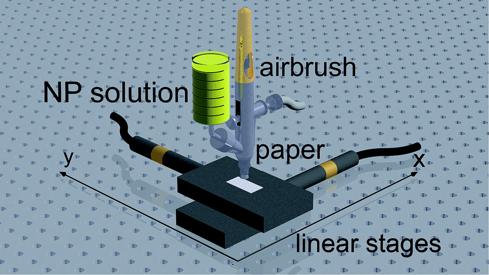 | ||
| Fig. 1 Scheme of the spray setup. | ||
The papers prepared with the two coating methods were dried after NP deposition at room temperature and cut into 4 × 4 mm test strips for the SERS experiments.
SERS measurements
SERS measurements were performed in solution and on test strips. For the measurements in solution, a mixture of 89 vol% of the synthesized NP solution, 1 vol% sodium chloride solution (1 M) and 10 vol% analyte solution (10−5 M) was used. For the SERS measurements on paper strips, 5 μL of analyte solution of different concentrations were dropped onto the test strips and dried at room temperature.Raman measurements were performed with two different setups, a Raman microscope and a process Raman setup, respectively. The Raman microscope LabRAM HR800 (Horiba) was used with the excitation wavelength 632.8 nm (9.1 mW) with a 10× objective (spot size Ø = 10 μm, filter: 10% laser intensity, laser power on sample = 1.2 kW cm−2) or a 60× immersion objective (spot size Ø = 1.5 μm, filter: 10% laser intensity, laser power on sample = 51.5 kW cm−2) and a grating with 300 lines per cm. The test strips were measured with the 10× objective and the solutions with the 60× immersion objective. The detection time and the number of averaged spectra for the measurements were 1 s and 20 spectra for solutions and 4 s and 3 spectra for test strips.
The process Raman setup, RamanRxn1 from Kaiser Optical Systems was used with an excitation wavelength of 785 nm, laser intensity from 50 to 400 mW and the PhAT probe (spot size: 6000 μm). The measurements were performed with two laser intensities: 200 mW, laser power on sample of 0.7 W cm−2, and 300 mW, laser power on sample of 1.1 W cm−2. The detection time was 20 s with accumulation of three spectra.
Results and discussion
Selection of NPs for the test strips
For the preparation of the SERS test strips, first, the NPs for the coating of the paper and second, the type of paper were selected. Important properties are reproducibility of the signal, a strong enhancement of the signal, stability and morphology of the coating on the papers. The synthesized NP solutions were pre-aggregated with sodium chloride according to the literature for SERS measurements in solution.43,44 The spectra of rhodamine 6G (10−6 M) in the different NP solutions are shown in the ESI (Fig. S3†). The comparison of the three SERS spectra shows that the silver NP solutions yield higher absolute signals compared to the gold NP solution for the used experimental parameters. However, the SERS intensities show strong variations between several measurements of the solutions. The differences in the intensities of the spectra can be explained by the NP concentration, size, shape and material. The AgNP-I and AuNP are relatively monodisperse and the shapes of the nanoparticles are spheres (Fig. S2†). In contrast to this, the AgNP-II are more polydisperse with different shapes (Fig. S2†). The average size (diameter) calculated from the size distribution in the TEM images of the nanoparticles and the medium concentrations of the nanoparticle solutions are for AgNP-I 9 nm and 1015 NP L−1, for AgNP-II 47 nm and 1014 NP L−1 and for the AuNP 26 nm and 5 × 10¹⁴ NP L−1. For rhodamine 6G silver is a better nanoparticle material45 and the larger nanoparticles give stronger SERS signals.42,46,47 In terms of signal intensity AgNP-II is the best nanoparticle solution but the polydispersity leads to problems regarding the reproducibility of the preparation and SERS enhancement factors of the test strips.Test strip preparation and characterization
For the preparation of the test strips, the behaviour of the NPs on the paper and the paper material is very important. In this work, conventional and commercially available cellulose and glass fibre paper were tested as substrate material for the test strips. The papers were coated with the different nanoparticle solutions and subsequently characterized by extinction spectra and SEM images.The coating of the paper with NPs was obtained by two different methods: dropping and spraying. The dropping method is very simple and fast, but leads to an inhomogeneous coating of the papers (Fig. 2A). The papers prepared by dropping of the NP solution show the coffee-ring effect,13,48 which makes it difficult to obtain test strips with a well-defined concentration of NPs per area unit. This leads to a low reproducibility of the coating and strong changes in the SERS signal. For a more reproducible coating, the spray method as described in the Experimental section was used and indeed the resulting strips show a much higher homogeneity (Fig. 2B). The concentration of the NPs per area unit can be controlled by the number of spray cycles. The current number of five cycles is a compromise for acceptable preparation time of test strips and a strong enough SERS signal. The intensity of the SERS signal increases with increasing concentration of NPs per area.21,31,49 The employed spray setup is easy and cheap to build as it is mainly based on a commercially available airbrush pistol. Furthermore, a large area of paper can be reproducibly coated with NPs and the NP solution can be varied. This gives more flexibility for coating of the paper compared to printing which would be the alternative deposition method. The differences in NP coating of paper by spraying and printing will be further investigated in future work.
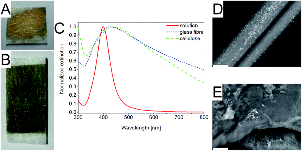 | ||
| Fig. 2 Glass fibre paper coated with AgNP-I by dropping (A) and spraying (B), extinction spectra of AgNP-I in solution, on glass fibre paper and on cellulose paper coated with the spray method (C) and SEM images of AgNP-I on glass fibre (D) and cellulose paper (E) prepared with the spray method. The scale bar in the SEM images is 5 μm. | ||
The extinction maximum of the plasmon band of the NP is shifted to higher wavelengths on the paper compared to solution and the extinction in the range from the extinction maximum to 800 nm is increased (Fig. 2C, S4 and S5†). In the SEM images of the papers (Fig. 2D and E) it is visible that the NPs form aggregates on the paper. These agglomerates on paper have a stronger extinction in the wavelength range from 400 nm to 800 nm compared to the NPs in solution.49,50 The aggregation of the NPs on paper is influenced by the type of the NPs (metal and stabilizing ligand), the deposition method and the type of the paper (cellulose or glass fibre). The NP agglomerates created by the spray method on glass fibre paper are more homogeneously distributed than on cellulose paper (Fig. 2D and E). Furthermore, the distribution of the NP on the fibres is superior with the spray method to the dropping method (Fig. S5†).
Two setups were used for the Raman measurements. The Raman microscope has the advantages of a small laser spot size (high resolution), precise focusing and high laser power for sample irradiation. These features are especially advantageous for flat surfaces. The process Raman system has a very large laser and detection spot size of 6 mm in diameter on the sample, which enables measuring an average of the sample and circumvents problems arising from different heights of the sample surface. However, the irradiation power on the sample is much lower compared to the Raman microscope and with this the Raman intensity.
The Raman measurements on uncoated and little coated cellulose paper show a reduction of fluorescence and background signals of the cellulose paper by the laser irradiation on the sample. This effect is not observed for the glass fibre paper for which the spectrum of the pure and coated paper is stable over several minutes irradiation time (Fig. S6†). Furthermore, the handling of the glass fibre paper is more convenient in terms of coating and also the background signal in the Raman spectra is lower as well as there are less Raman signals compared to cellulose (Fig. S6†). Additionally, cellulose shows strong fluorescence for a shorter excitation laser wavelength (633 nm, spectra not shown). Therefore, glass fibre paper was selected as substrate for the SERS test strips and will be used for further optimization.
For further characterization of the test strips, SERS measurements with three classical SERS reporters, rhodamine 6G, 4-aminothiophenol and adenine, were performed. All three analytes yielded SERS spectra with acceptable intensities (Fig. S7†).
The spectra of adenine were evaluated in terms of relative standard deviation (RSD) of the measurements to select the best combination of coating method, NPs and Raman setup for the test strip applications. Further information on the RSD calculation can be found in the ESI.†
For the measurements with the process Raman setup, the RSD is much lower compared to measurements with the Raman microscope on the same sample (Fig. 3). The RSD of the measurements of test strips prepared by the dropping method is higher compared to preparation by the spray method, e.g., an RSD of 24% is found for dropping of AgNP-I yet only 11% for spraying. Not only the deposition methods and the Raman setups led to differences in the reproducibility of the measurements but also the used NP solutions did. The lowest RSD was observed for measurements with AgNP-I (RSD = 11%) and the highest for AgNP-II (RSD = 29%). The lowest concentration that could be detected on prepared test strips by spraying of AgNP-I was 10−9 M for rhodamine 6G with the Raman microscope.
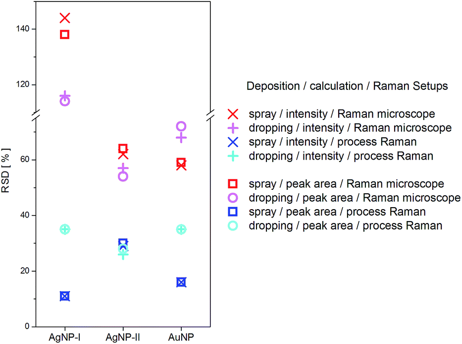 | ||
| Fig. 3 RSD of the Raman signal of adenine spectra at 735 cm−1 (10−4 M) measured with the Raman microscope (red and pink) and the process Raman (blue and cyan) on glass fibre paper. The red and blue symbols are from test strips prepared by the spray method and the pink and cyan symbols are from test strips prepared by the dropping method. Peak intensities (cross and plus) and peak areas (squares and circles) were evaluated, respectively. | ||
Taking all effects, especially the reproducibility of the SERS measurement, into account, glass fibre paper in combination with AgNP-I solution and coating by the spray method was selected in combination with the process Raman setup for a first prototype application.
Application of the test strips
In a prototype application of the developed test strips, we tested the two antibiotics enoxacin and enrofloxacin. SERS spectra of the antibiotics on test strips are shown in Fig. 4 and are in good agreement with the literature35–38i.e., both antibiotics can be identified rapidly and easily with the test strips. The lowest concentration of the antibiotics that can be detected with the current test strips and detection setup is 10−5 M for the most prominent signals (enoxacin = 1411 cm−1/enrofloxacin = 1388 cm−1). Because the focus of this work lay on the optimization of the reproducibility of the measurements, the sensitivity of the approach needs to be improved for the actual application. Current work is undertaken into this direction.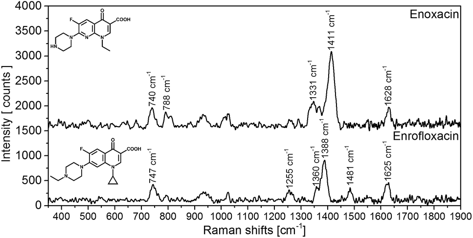 | ||
| Fig. 4 SERS spectra on test strips of enoxanin (10−4 M) and enrofloxacin (10−4 M). The spectra are background corrected. | ||
Dynamic range
To investigate the capability of the test strip SERS measurements for quantification of the analyte, a concentration series of adenine in a concentration range from 10−4 M to 10−8 M was measured employing AgNP-I on glass fibre test strips combined with the process Raman.The strongest Raman band of adenine at 735 cm−1 was used for assessment. For this purpose, the bands between 710 cm−1 to 770 cm−1 of the raw spectra were baseline-corrected and the averaged blank was subtracted. The entire data evaluation procedure is described in the ESI.†
It is evident from Fig. 5B that the data do not follow a linear correlation between SERS intensity and analyte concentration but instead can be fitted and interpreted with a non-linear Langmuir isotherm (eqn (1)) as explained below.18,31,39,41 A logarithmic plot of the concentration (Fig. 5C) further supports this observation and also hints at the fact that the data points at low concentration show a certain offset. After processing of the data and removing outliers as described in Table S1,† the linearized form of the Langmuir isotherm (eqn (2)) seems to describe the measured data rather well, see Fig. 5D.
 | (1) |
 | (2) |
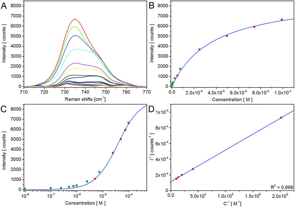 | ||
| Fig. 5 Concentration dependent intensity of the Raman band of the ring breathing mode of adenine at 735 cm−1 ± 1 cm−1 (A), classic plot of the intensity vs. concentration (B), logarithmic plot of the data (C) (green points mark outliers) and linear plot of the processed data (D) with the fitting curves of the Langmuir isotherm. | ||
Data interpretation according to the Langmuir isotherm model requires different assumptions. The Langmuir model assumes that all adsorption sites on the surfaces are equivalent, that every site can only be occupied by one molecule in a monolayer and that the adsorbed molecules do not interact with each other. Since the enhancement effect of SERS is known to critically depend on distance between the analyte molecule and the nanoparticle surface, this matches with the assumption that only the first monolayer of molecules adsorbed on the surface produces a significant SERS signal and therefore with the assumption of a monolayer on the surface of the Langmuir model. With the additional assumption that the measured intensity signal is an average over the distribution of the analytes on the NPs and agglomerates, we obtain a linear correlation between SERS intensity and the analyte concentration on the surface of the NPs or agglomerates in a reciprocal plot (Fig. 5D). With the description of the adsorption of the analytes on the surface with the Langmuir isotherm, the measured data for SERS intensity vs. analyte concentration can be fitted with the Langmuir isotherm.
The Langmuir fit is not only in good agreement for the SERS band of adenine at 735 cm−1 (Fig. 5B–D) but also for the bands at 1336 cm−1 and 1457 cm−1 as shown in the ESI (Fig. S8 and S9†). The limit of detection and dynamic range of the system can accordingly be derived from the linear plot (Fig. 5D). The limit of detection (=LOD) is 8 × 10⁻⁷ M and the dynamic range stretches up to at least 2 × 10⁻³ M. The parameter K (adsorption constant of the given test strips and analyte) and ISERS,max of the linear plot are specified in the ESI.†
However, not all SERS properties can be explained with the model, e.g. the model neglects “hot spots”. Furthermore, due to the necessity of a reproducible average signal the model is limited in the low concentration range. Nonetheless, the simple model can explain the measured data in the relevant concentration region for the application of SERS test strips.
Conclusions
In this paper, we have reported a new and simple approach for the coating of papers with metal nanoparticles by an airbrush to prepare test strips for SERS analysis. The coating method in combination with the glass fibre paper, AgNP-I and the process Raman setup yielded a promising reproducibility of the measurements with an RSD of 11%. The glass fibre paper strips are better suitable for the preparation and Raman measurements compared with cellulose paper. These optimized strips and measurement setup were used for the identification of analytes and for the calibration of adenine in the dynamic range of 2 × 10⁻³ M to 8 × 10⁻⁷ M in solution. The concentration series could be fitted well to a Langmuir isotherm, which in a first approximation reveals that increasing adsorption of analyte molecules onto the surface of the NPs determines the dynamic behaviour of the system at moderate to high concentrations. The approach presents a promising way to conceive versatile and simple SERS assays for various analytical applications.Acknowledgements
The authors thank Sören Selve from Zentraleinrichtung Elektronenmikroskopie (ZELMI) of the TU Berlin for the TEM measurements and Ines Feldmann from BAM for SEM measurements.References
- B. Sharma, R. R. Frontiera, A.-I. Henry, E. Ringe and R. P. Van Duyne, Mater. Today, 2012, 15, 16–25 CrossRef CAS.
- D. Cialla, A. März, R. Böhme, F. Theil, K. Weber, M. Schmitt and J. Popp, Anal. Bioanal. Chem., 2012, 403, 27–54 CrossRef CAS PubMed.
- S. Nie and S. R. Emory, Science, 1997, 275, 1102–1106 CrossRef CAS PubMed.
- J. Kneipp, H. Kneipp and K. Kneipp, Chem. Soc. Rev., 2008, 37, 1052–1060 RSC.
- M. Potara, M. Baia, C. Farcau and S. Astilean, Nanotechnology, 2012, 23, 055501 CrossRef PubMed.
- M. Fleischmann, P. J. Hendra and A. J. McQuillan, Chem. Phys. Lett., 1974, 26, 163–166 CrossRef CAS.
- D. L. Jeanmaire and R. P. Van Duyne, J. Electroanal. Chem., 1977, 84, 1–20 CrossRef CAS.
- M. G. Albrecht and J. A. Creighton, J. Am. Chem. Soc., 1977, 99, 5215–5217 CrossRef CAS.
- P. L. Stiles, J. A. Dieringer, N. C. Shah and R. P. Van Duyne, Annu. Rev. Anal. Chem., 2008, 1, 601–626 CrossRef CAS PubMed.
- P. C. Lee and D. Meisel, J. Phys. Chem., 1982, 86, 3391–3395 CrossRef CAS.
- V. Peksa, M. Jahn, L. Štolcová, V. Schulz, J. Proška, M. Procházka, K. Weber, D. Cialla-May and J. Popp, Anal. Chem., 2015, 87, 2840–2844 CrossRef CAS PubMed.
- X. Tang, R. Dong, L. Yang and J. Liu, J. Raman Spectrosc., 2015, 46, 470–475 CrossRef CAS.
- W. W. Lee, V. A. Silverson, C. P. McCoy, R. F. Donnelly and S. E. Bell, Anal. Chem., 2014, 86, 8106–8113 CrossRef CAS PubMed.
- J. C. Hulteen and R. P. Van Duyne, J. Vac. Sci. Technol., A, 1995, 13, 1553–1558 Search PubMed.
- M. Fan, G. F. S. Andrade and A. G. Brolo, Anal. Chim. Acta, 2011, 693, 7–25 CrossRef CAS PubMed.
- C. D. Tran, Anal. Chem., 1984, 56, 824–826 CrossRef CAS.
- W. W. Yu and I. M. White, Anal. Chem., 2010, 82, 9626–9630 CrossRef CAS PubMed.
- W. W. Yu and I. M. White, Analyst, 2013, 138, 1020–1025 RSC.
- C. H. Lee, M. E. Hankus, L. Tian, P. M. Pellegrino and S. Singamaneni, Anal. Chem., 2011, 83, 8953–8958 CrossRef CAS PubMed.
- M. L. Cheng, B. C. Tsai and J. Yang, Anal. Chim. Acta, 2011, 708, 89–96 CrossRef CAS PubMed.
- Y. H. Ngo, D. Li, G. P. Simon and G. Garnier, Langmuir, 2012, 28, 8782–8790 CrossRef CAS PubMed.
- P. M. Fierro-Mercado and S. P. Hernández-Rivera, Int. J. Spectrosc., 2012, 2012, 7 Search PubMed.
- J. Wang, L. Yang, B. Liu, H. Jiang, R. Liu, J. Yang, G. Han, Q. Mei and Z. Zhang, Anal. Chem., 2014, 86, 3338–3345 CrossRef CAS PubMed.
- W. Zhang, B. Li, L. Chen, Y. Wang, D. Gao, X. Ma and A. Wu, Anal. Methods, 2014, 6, 2066–2071 RSC.
- B. Li, W. Zhang, L. Chen and B. Lin, Electrophoresis, 2013, 34, 2162–2168 CrossRef CAS PubMed.
- Y. Zhu, M. Li, D. Yu and L. Yang, Talanta, 2014, 128, 117–124 CrossRef CAS PubMed.
- B. Nie, Q. Zhou, J. He and F. Yang, J. Raman Spectrosc., 2015, 46, 211–216 CrossRef CAS.
- A. Berthod, J. J. Laserna and J. D. Winefordner, J. Pharm. Biomed. Anal., 1988, 6, 599–608 CrossRef CAS PubMed.
- R. Zhang, B. B. Xu, X. Q. Liu, Y. L. Zhang, Y. Xu, Q. D. Chen and H. B. Sun, Chem. Commun., 2012, 48, 5913–5915 RSC.
- L.-L. Qu, D.-W. Li, J.-Q. Xue, W.-L. Zhai, J. S. Fossey and Y.-T. Long, Lab Chip, 2012, 12, 876–881 RSC.
- E. P. Hoppmann, W. W. Yu and I. M. White, Methods, 2013, 63, 219–224 CrossRef CAS PubMed.
- M. Figueroa, K. Pourrezaei and S. Tyagi, AIP Conf. Proc., 2012, 1461, 47–53 CrossRef CAS.
- H.-X. Gu, D.-W. Li, L. Xue, Y.-F. Zhang and Y.-T. Long, Analyst, 2015, 140, 7934–7938 RSC.
- R. Sato-Berrú, R. Redón, A. Vázquez-Olmos and J. M. Saniger, J. Raman Spectrosc., 2009, 40, 376–380 CrossRef.
- L. He, M. Lin, H. Li and N.-J. Kim, J. Raman Spectrosc., 2010, 41, 739–744 CAS.
- Y. Zhang, Y. Huang, F. Zhai, R. Du, Y. Liu and K. Lai, Food Chem., 2012, 135, 845–850 CrossRef CAS PubMed.
- Y. Xu, Y. Du, Q. Li, X. Wang, Y. Pan, H. Zhang, T. Wu and H. Hu, Food Anal. Methods, 2014, 7, 1219–1228 CrossRef.
- U. Neugebauer, A. Szeghalmi, M. Schmitt, W. Kiefer, J. Popp and U. Holzgrabe, Spectrochim. Acta, Part A, 2005, 61, 1505–1517 CrossRef CAS PubMed.
- W. W. Yu and I. M. White, Analyst, 2013, 138, 3679–3686 RSC.
- S. Kasera, F. Biedermann, J. J. Baumberg, O. A. Scherman and S. Mahajan, Nano Lett., 2012, 12, 5924–5928 CrossRef CAS PubMed.
- I. Izquierdo-Lorenzo, S. Sanchez-Cortes and J. V. Garcia-Ramos, Langmuir, 2010, 26, 14663–14670 CrossRef CAS PubMed.
- J. Zeng, X. Xia, M. Rycenga, P. Henneghan, Q. Li and Y. Xia, Angew. Chem., Int. Ed., 2011, 50, 244–249 CrossRef CAS PubMed.
- N. Leopold and B. Lendl, J. Phys. Chem. B, 2003, 107, 5723–5727 CrossRef CAS.
- C. L. Zhang, K. J. Wang, D. J. Han and Q. Pang, Spectrochim. Acta, Part A, 2014, 122, 387–391 CrossRef CAS PubMed.
- M. L. Coluccio, G. Das, F. Mecarini, F. Gentile, A. Pujia, L. Bava, R. Tallerico, P. Candeloro, C. Liberale, F. De Angelis and E. Di Fabrizio, Microelectron. Eng., 2009, 86, 1085–1088 CrossRef CAS.
- V. Joseph, A. Matschulat, J. Polte, S. Rolf, F. Emmerling and J. Kneipp, J. Raman Spectrosc., 2011, 42, 1736–1742 CrossRef CAS.
- Z. H. Zhu, T. Zhu and Z. F. Liu, Nanotechnology, 2004, 15, 357–364 CrossRef CAS.
- A. Nilghaz, L. Zhang and W. Shen, Chem. Eng. Sci., 2015, 129, 34–41 CrossRef CAS.
- P. Fierro-Mercado, B. Renteria-Beleño and S. P. Hernández-Rivera, Chem. Phys. Lett., 2012, 552, 108–113 CrossRef CAS.
- C. G. Blatchford, J. R. Campbell and J. A. Creighton, Surf. Sci., 1982, 120, 435–455 CrossRef CAS.
Footnote |
| † Electronic supplementary information (ESI) available: Extinction spectra of the NP solutions, size distributions of NPs, SERS spectra of rhodamine 6G in NP solutions, extinction spectra of NPs on paper, Raman spectra of papers, SERS spectra of three analytes, RSD calculation, data processing of the spectra of the concentration series, dynamic range determination, and Langmuir fit. See DOI: 10.1039/c5ay03096j |
| This journal is © The Royal Society of Chemistry 2016 |