 Open Access Article
Creative Commons Attribution 3.0 Unported Licence
Gas phase chemical vapor deposition chemistry of triethylboron probed by boron–carbon thin film deposition and quantum chemical calculations†
Mewlude
Imam
 *ab,
Konstantin
Gaul
c,
Andreas
Stegmüller
c,
Carina
Höglund
ab,
Jens
Jensen
a,
Lars
Hultman
a,
Jens
Birch
a,
Ralf
Tonner
*c and
Henrik
Pedersen
 *a
*a
aDepartment of Physics, Chemistry, and Biology (IFM), Linköping University, SE-58183 Linköping, Sweden. E-mail: yimma@ifm.liu.se; henrik.pedersen@liu.se
bEuropean Spallation Source ESS AB, P. O. Box 176, SE-22100, Lund, Sweden
cFachbereich Chemie and Material Sciences Center, Philipps-Universität Marburg, Hans-Meerwein-Straße 4, D-35032 Marburg, Germany. E-mail: tonner@chemie.uni-marburg.de
First published on 17th September 2015
Abstract
We present triethylboron (TEB) as a single-source precursor for chemical vapor deposition (CVD) of BxC thin films and study its gas phase chemistry under CVD conditions by quantum chemical calculations. A comprehensive thermochemical catalogue for the species of the gas phase chemistry of TEB is examined and found to be dominated by β-hydride eliminations of C2H4 to yield BH3. A complementary bimolecular reaction path based on H2 assisted C2H6 elimination to BH3 is also significant at lower temperatures in the presence of hydrogen. Furthermore, we find a temperature window of 600–1000 °C for the deposition of X-ray amorphous BxC films with 2.5 ≤ x ≤ 4.5 from TEB. Films grown at temperatures below 600 °C contain high amounts of H, while temperatures above 1000 °C result in C-rich films. The film density and hardness are determined to be in the range of 2.40–2.65 g cm−3 and 29–39 GPa, respectively, within the determined temperature window.
Introduction
Boron forms technically very interesting compounds including boron carbides (B4C). The rhombohedral phase of B4C is a very hard, light-weight material with high chemical and thermal stability as well as high wear resistance.1 Although it is nominally called B4C, the carbon concentration of the compound can vary from 9 to 20 at% and exist as a stable single phase in a large homogeneous region from B4C to B10.4C.2,3 Boron nitride (BN) is isoelectronic to carbon and can form compounds with either sp3-hybridized or sp2-hybridized bonds. The most studied sp3-hybridized phase is the cubic (c-BN), which is isoelectronic to diamond, but there is also a wurtzite phase (w-BN), which is isostructural to Lonsdaleite (hexagonal diamond). The interest for c-BN mainly stems from the phase similarities to diamond: c-BN is regarded as the hardest material after diamond and developed as hard coatings for cutting tools. The sp2-hybridized BN can crystallize into two different phases: hexagonal (h-BN) and rhombohedral (r-BN) are envisioned as promising materials for photonics and electronics.4 The hexagonal polytype is isostructural to graphite and can, like graphite, form a stable two-dimensional material. Single layers of h-BN are used in combination with graphene in the exploration of electronics based on two-dimensional materials.5 It is reported both theoretically and experimentally that h-BN has a direct band gap and is likely around 6 eV.4 Moreover, employing Mg as a p-type dopant for sp2-BN shows a lower activation energy of the Mg acceptor of ∼31 meV, this makes it more attractive for deep UV application than AlN.4 Except all the applications mentioned above, there is one emerging application for boron-based materials, both B4C6 and BN7 are promising neutron converting layers in new generation neutron detectors. The isotope 10B, with 20% natural abundance, has a high absorption cross-section for thermal neutrons, and reacts in either of the reactions (1) and (2), when a neutron is captured:| 94%: 10B + n → 7Li(0.84 MeV) + 4He(1.47 MeV) + γ(0.48 MeV) | (1) |
| 6%: 10B + n → 7Li(1.02 MeV) + 4He(1.78 MeV) | (2) |
Boron-based compounds are often used in the form of thin films with thicknesses from a single atomic layer to several micrometers. One of the routes to fabricate such films is chemical vapor deposition (CVD), which is a family of techniques where thin films are formed from chemical reactions between volatile molecules containing the atoms needed for the thin film. Volatile boron based molecules can be made by forming boron hydrides, typically diborane (B2H6), boron halides, typically boron trichloride (BCl3), and organoboranes, typically triethylboron (B(C2H5)3). The boron hydrides are attractive CVD precursors as they apart from boron contain only hydrogen. This leads to a low risk of the incorporation of unwanted atoms into the films since hydrogen is often used as a carrier gas in CVD. The boron hydrides, especially B2H6, are however very toxic and explosive and therefore problematic to handle. The boron halides have been successfully used for CVD of boron carbides but require rather high process temperatures of 1000–1300 °C.10 The boron halides, particularly BCl3, are not suited as precursors for BN as the HCl by-product will form solid NH4Cl together with the typical nitrogen precursor ammonia (NH3) which may damage the vacuum pump of the CVD system. The hydrogen-halide by-products as a result of employing boron halides are also very corrosive and can badly affect metallic substrates used for CVD of single layer BN11 or as a basis for neutron detectors.6 Organoboranes are therefore an attractive class of precursor molecules for CVD of boron-based materials. The most common organoborane is B(C2H5)3, hereafter referred to as TEB. TEB has a melting point of −92.8 °C and boils at 95 °C.12 The vapor pressure (P) in bar for TEB at a temperature (T) in Kelvin is calculated using log(P) = 2.91408 − (753.261/(T − 112.631)).13 It has successfully been used for CVD of both boron–carbon (BxC)14 and BN15 thin films. Also trimethylboron (B(CH3)3) and tributylboron (B(C4H9)3) have been reported for CVD of boron–carbon thin films.16 The organoboranes are particularly interesting for boron carbides as they can function as both boron and carbon precursors.
For any material, a high level of understanding of the chemistry of the precursor molecules is of great importance when improving and developing CVD processes. The CVD chemistry of organoboranes has not been fully studied. The TEB molecule has been suggested to undergo β-hydride elimination in the gas phase at temperatures above 300 °C,16 which was used as a basis for a speculation around the CVD chemistry of BN CVD at 1500 °C.15 A gas phase chemistry mechanism for TEB based on β-hydride elimination of C2H4 and H2 assisted elimination of C2H6 has been sketched to explain the film deposition of BxC films from TEB at 400–600 °C.14 However, these attempts to explain the CVD chemistry are only based on the experimental results from deposited BxC and BN films.
In this paper, we aim to establish a comprehensive gas phase CVD chemistry for TEB. We use the ability of TEB to act as a single-source precursor for BxC films, allowing us to study the film deposition from using only TEB diluted in H2 or Ar. Any gas phase interactions with other precursor molecules are thus avoided. In addition to the film deposition, possible gas phase reactions, both within the TEB molecule (unimolecular) and between the TEB molecule and the H2 carrier gas (bimolecular), are studied by quantum chemical calculations. A gas phase chemical mechanism for TEB under CVD conditions is then suggested based on the combined experimental and quantum chemical results. The results presented here may be useful in the further understanding and development of CVD of boron-based materials.
Methods
Film deposition
A hot-wall CVD reactor equipped with an inductively heated, SiC-coated graphite susceptor was used for the deposition of BxC films from TEB. Further details of this type of CVD reactor are described in ref. 17. As a carrier gas, palladium membrane-purified H2 or Ar (99.9997%) was used. The process pressure was controlled by a throttle valve and set to 50 mbar. The TEB from SAFC Hitch was of semiconductor grade purity and kept in a stainless steel bubbler immersed in a temperature-controlled water/glycol bath to ensure a constant, well-controlled temperature of 7 °C, which gives a TEB vapor pressure of 28.7 mbar. A small flow of the carrier gas, controlled by an electronic mass flow controller, was bubbled through the liquid TEB. The pressure in the bubbler was set by an electronic pressure controller. The TEB concentration in the gas mixture in the reactor was 0.06%, as determined by taking the ratio of TEB flow to the total gas flow in the chamber. Single-crystal, (100)-oriented Si wafers were used as substrates for the deposition. Prior to deposition, the substrates were ultrasonically cleaned with acetone and isopropanol, and dried with dry N2.Film characterization
The film thickness, used to calculate the deposition rate, was determined by cross-sectional scanning electron microscopy (SEM) on cleaved samples using a LEO 1550 Gemini SEM equipped with a field emission gun (FEG). Time-of-flight elastic recoil detection analysis (ToF-ERDA), a technique that provides relative amounts of all included elements, was used to determine elemental composition of films using 36 MeV iodine ions. The experimental details of the ToF-ERDA can be found elsewhere.18,19 Film crystallinity was studied by XRD in a Bragg–Brentano configuration within the 20–80° scanning range using Cu-Kα radiation. X-ray reflectivity (XRR) has been carried out on samples using a Philips X′Pert Pro MRD diffractometer equipped with a hybrid mirror monochromator and a 2-bounce Ge 220 triple-axis crystal analyzer. Film densities were determined by fitting the XRR data using X′pert reflectivity software. Film hardness was determined with 20 indents for each sample, with a load of 50 mN using a UMIS 2000 nanoindentation system.Quantum chemical calculations
The investigated molecular structures were optimized at the density functional theory (DFT) level using the GGA functional PBE20 including an atomic pairwise dispersion correction scheme (DFT-D3(BJ)).21,22 Subsequently, the structures were optimized with MP2 and single-point calculations at the CCSD(T) level were carried out based on optimized MP2 structures. These calculations were performed with the def2-TZVPP23 basis set and the RI (DFT and MP2)24 as well as the MARIJ (for DFT) approximation.25Calculations were performed using Turbomole 6.626 and Gaussian0927 quantum chemistry codes by a combination of optimization algorithms from Gaussian with energies and gradients from Turbomole. MP2 and CCSD(T) calculations were carried out using the Turbomole module ricc2. In the case of DFT calculations, a fine integration grid (m4) was used and SCF convergence criteria were set to 10−9 a.u.
Initial guesses for transition states (TSs) were generated by the semi-empirical method PM628 and the TS optimization algorithm as well as the quadratic-synchronous transit method of Gaussian09.29 In some cases, existing TS structures from similar reactions of triethylaluminium or triethylgallium (TEGa) were used.30 The TS structures were refined with the TS optimization algorithm using PBE-D3(BJ)/def2-TZVPP and MP2/def2-TZVPP methods as outlined above. Intrinsic reaction coordinate calculations (IRC) were performed using Gaussian09.31 The identification of minima (no imaginary frequencies) and TS (one imaginary frequency) and the derivation of thermodynamic properties were achieved by calculations of the Hessian and derivation of vibrational spectra using Turbomole (aoforce module). Thermodynamic corrections of free atoms were computed using the Sackur–Tetrode equation.32 All closed-shell molecules exhibit singlet ground states, while all radicals were calculated in the doublet state. The thermodynamic corrections were computed at T = 400–1200 °C and p = 0.05 atm (approx. 50 mbar). These settings represent typical CVD reactor conditions. Entropy corrections are sensitive to even small errors in the low-frequency vibrations of the molecule. Thus, absolute Gibbs energies at high temperatures have to be interpreted carefully. However, trends are less sensitive to this issue.
Based on Gibbs reaction energies (ΔG) and barriers (ΔG†) for the computed decomposition reactions, a kinetic Monte Carlo (KMC) simulation was performed to derive product distributions under different deposition conditions. Arrhenius-type reaction rates were considered within a temperature range of 600 to 1600 K (327–1327 °C) applying a constant pre-exponential factor (kBT/h, with kB being the Boltzmann and h the Planck constant) for all possible processes. Thermodynamic corrections for electronic energies were computed explicitly for selected temperatures (see above) and interpolated linearly. The system was modelled as a lattice-independent gas phase population with a relative concentration of the initial precursor TEB (0.5 mbar) of 1% with respect to the carrier gas (H2 or Ar, 50 mbar). The rate of each decomposition reaction was evaluated for each iteration and used to determine the individual probability of success, which is weighted against the total rate (sum of all possible process rates) for the system at the given state. Based on a random number check, one reaction was selected to take place against its probability and the system updated with the generated products of the process (and reactants annihilated). Each simulation was performed over 100![[thin space (1/6-em)]](https://www.rsc.org/images/entities/char_2009.gif) 000 iterations ensuring the system to reach equilibrium. Further details of the method will be reported elsewhere.
000 iterations ensuring the system to reach equilibrium. Further details of the method will be reported elsewhere.
Results and discussion
Deposited films
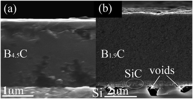
Initial results for films deposited at 400–600 °C were reported in ref. 14. For a more complete picture of TEB as a CVD precursor for BxC films, we present results for films deposited at 700–1200 °C and include the low temperature results to show a wide temperature range from 400 °C to 1200 °C.Films appear black and shiny when they are deposited at 700–1000 °C in a H2 atmosphere and above 1000 °C get less shiny and vary in color more blacker. Films deposited in an Ar atmosphere also look black and shiny at 700–900 °C, then tend to be more grayish and less shiny with increasing temperature. All deposited films adhere well to the Si(001) substrates regardless of the deposition atmosphere and are dense in typical cross-sectional SEM images, as shown in Fig. 1(a). For films deposited above 900 °C, voids are observed in the interface region in both atmospheres, which is likely the result of substrate and film solid state reaction, see Fig. 1(b), as it has been reported for Si(001) substrates used in CVD of SiC using silane and propane in H2.33
The B and C content of the deposited films, as determined by ToF-ERDA, are given in Fig. 2. For the films deposited at up to 1000 °C in a H2 atmosphere, B is the dominating element and increases slightly when the deposition temperature increases from 400 °C to 700 °C (71–82 at%), while temperatures are in the range of 700–1000 °C, the B content is more or less constant (77 ± 5 at%). At further high temperatures, i.e., 1100 °C and 1200 °C, B content drops drastically to 8 at%. The C content in the films increases throughout the whole temperature range. At lower temperatures (400–500 °C), C content is less than 10 at% and varies between 17 and 28 at% for temperatures between 600 and 1000 °C. At highest temperatures, where the B content drops to 8 at%, C content is as high as 92 at%. The C enrichment in the films grown at the highest temperatures explains why they look blacker than the B-rich ones.
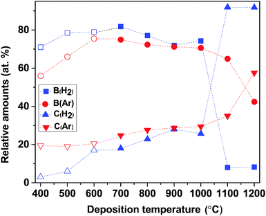 | ||
| Fig. 2 ToF-ERDA data showing the relative amounts of B and C of films deposited in H2 and Ar atmospheres, respectively, as a function of deposition temperature. Open symbols correspond to data points taken from our previous publication.14 | ||
For depositions in an Ar atmosphere, B is again seen to be the dominant element in the films and follows the same trend as the films deposited in H2: increases with increasing deposition temperature at 400–600 °C (56–76 at%), fairly stable at 600–1000 °C (71 ± 1 at%), and significantly decreases at temperatures above 1000 °C, see Fig. 2. The C content in the films deposited in an Ar atmosphere reveals three functions of the temperature range: in the range of 400–600 °C, it is constant at ∼20 at% and increases gradually from 25 to 35 at%; when the temperature increases from 600 to 1100 °C, at 1200 °C reaches its maximum of 58 at%. The lower C content in the films, compared to that obtained in H2, can explain why films deposited in Ar look greyish while those deposited in H2 became more blacker at temperatures above 1000 °C.
In Fig. 3, the B-to-C (B/C) ratios are plotted as a function of deposition temperature. It shows that at lower temperatures (400 and 500 °C), B/C ratios in H2 deviate from the B/C ratios in Ar. At higher temperature (600–1000 °C) the difference between the two atmospheres decreases with increasing temperature. As it is noted above, the abrupt drop in B content (and increase in C) above 1000 °C results in the lowest B/C ratio in H2 while in Ar, it slightly decreases with increasing temperature.
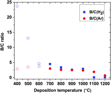 | ||
| Fig. 3 B/C ratios in H2 and Ar atmospheres as a function of deposition temperature. Open symbols correspond to data points taken from our previous publication.14 | ||
In Fig. 4, the H content in the films is plotted as a function of temperature. It can be seen that H is not affected by the deposition atmosphere, but solely by deposition temperature, which suggests that any H in the films originates from the TEB precursor rather than from the carrier gas. By increasing temperature from 400 °C to 600 °C, H content in the films drops from 24 to 4 at%. For temperatures above 600 °C, H levels are constantly below 1 at% showing that these temperatures enable depositions of nearly H-free films. This temperature dependent decrease in H content suggests that either an out diffusion of H from the films and/or a more favorable surface chemistry is activated only for deposition temperatures higher than 600 °C. Detailed elemental compositions in all films are given in ESI,† Table S1. For films deposited below 700 °C, oxygen (O) contamination in the films is as low as 0.5–1 at%14 while for films deposited at temperatures above 700 °C, the amount of O is below the detection limit. Other impurities, like N and Ar, are below the detection limit for ToF-ERDA of 0.05 at%.
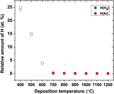 | ||
| Fig. 4 ToF-ERDA data showing the relative amount of H in H2 and Ar atmospheres, respectively, as a function of deposition temperature. Open symbols correspond to data points taken from our previous publication.14 | ||
The deposition rate varies with both the deposition atmosphere and temperature, as shown in Fig. 5. Generally, a higher deposition rate is obtained in Ar, which indicates that films are etched more in a H2 atmosphere than in Ar. In both atmospheres (within the temperature range giving B-rich films), the deposition rates increase with increasing temperature and maxima of 2 μm h−1 in H2 and 4.5 μm h−1 in Ar are obtained at 900 °C. The deposition rate increases again starting from 1000 °C in H2 and 1100 °C in Ar, respectively. These observed variations in the deposition rate and the B/C ratio with deposition temperature (Fig. 3) in combination with the elemental composition of the films described above imply that the deposition chemistry changes substantially with temperature, as discussed below. Estimations of activation energy for CVD of BxC films from TEB by the Arrhenius plot are thus not meaningful.
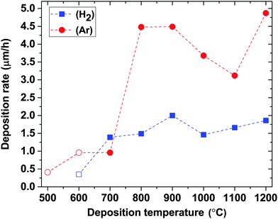 | ||
| Fig. 5 Deposition rates in H2 and Ar atmospheres as a function of deposition temperature. Open symbols correspond to data points taken from our previous publication.14 | ||
Regardless of the deposition atmosphere, all films deposited at 1000 °C or below are X-ray amorphous, as shown for films deposited at 700–1200 °C in Fig. 6 and as previously reported for films deposited at 400–600 °C.14 The peak that is seen at 26.3° for films deposited at 1100 °C and 1200 °C is more distinct for films deposited in H2 (Fig. 1(a)) than Ar (Fig. 1(b)) atmospheres where the peaks are much broader, and is assigned to the 002 peak of graphite.34 This matches well with the high C content in the films deposited at these temperatures as described above. The small peak with very low intensity initiating at around 60° is also found to be very close to the 103 peak of graphite. Besides the graphite peaks, one more peak is seen at 41.3°, which fits well with the 002 peak of 3C-SiC,35 in agreement with the observed interface reaction at high temperatures (>900 °C), see Fig. 1(b). The lack of the Si signal in the ERDA analysis is due to the limited depth sampling in our experiments not reaching the film/substrate interface region. According to their peak positions, the two broad bumps arising at 35° and 38° in an Ar atmosphere are assumed to be originated from peaks 002 and 112 of B50C1.8.
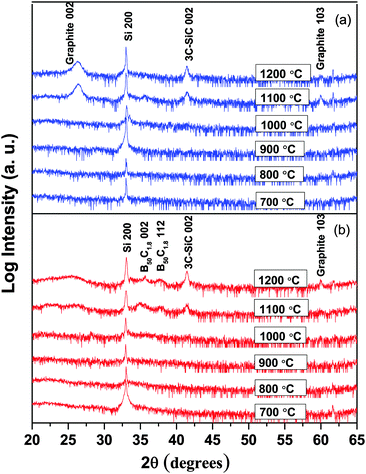 | ||
| Fig. 6 X-ray diffractograms of BxC films deposited at temperatures between 700 and 1200 °C in (a) H2 and (b) Ar atmospheres. | ||
The densities of selected films are listed in ESI,† Table S2. Films with B/C ratios of about 4.5, deposited at 600 °C and 700 °C in a H2 atmosphere, have gravimetric densities of 2.42 ± 0.05 g cm−3, which are close to the bulk density36 of B4C: 2.52 g cm−3 as well as the density of sputtered films:6 2.45 g cm−3. Relatively high film hardness, in the range of 37–39 GPa, is measured for the amorphous BxC films deposited at 800–900 °C. The hardness and the bending shape of samples (most clear for films deposited in Ar) indicate that films experienced internal compressive stresses. More details of the measured film hardness are given in ESI,† Fig. S1.
Computational investigation of TEB decomposition reactions
Quantum chemical computations at the DFT and wave function based MP2 and CCSD(T) levels are carried out to understand the elementary reactions of TEB occurring in the gas phase. To this end, a large catalogue of uni-molecular decomposition reactions for TEB has been set up and augmented by H2-assisted decomposition reactions to elucidate the role of the carrier gas (H2 or Ar) as found in the experimental part described above. As a starting point for the reaction catalogue, our previous work on the gas phase reactivity of TEGa is used.30 Five possible reaction types are studied in this work: (a) radical cleavages, (b) β-hydride eliminations, (c) alkane eliminations, (d) H2-eliminations, and (e) α-H-abstraction reactions. We summarize the major findings from this large set of reactions. The complete reaction catalogue and thermodynamic data for different temperatures as well as a test of the DFT methodology can be found in the ESI.†Most of the reactions investigated are endergonic under the given conditions. The electronic reaction energies of radical cleavages are in the range of 300–500 kJ mol−1 and the Gibbs energies for nearly all reactions are above 200 kJ mol−1 even at temperatures above 700 °C. The reaction energies of most alkane and H2 eliminations are in the same range, whereby the Gibbs reaction energies at high temperatures are slightly lower due to high entropic contributions. One α-H elimination reaction that results in ethane as a reaction product and one α-H abstraction of TEB (see ESI,† Fig. S2) are found to be thermodynamically accessible (ΔG < 0 kJ mol−1 for T > 500 °C). Most importantly, the β-hydride eliminations are thermodynamically accessible at temperatures T > 500 °C for the TEB precursor as well as the resulting intermediates (reactions (3)–(5) in Table 1). For these exergonic or slightly endergonic reactions, TS searches are also carried out. It is found that the reaction barriers for all uni-molecular reactions lie above 200 kJ mol−1 (T = 500 °C) except for the β-hydride eliminations shown in Table 1.
| Reaction | ΔE | ΔG | ΔE† | ΔG† |
|---|---|---|---|---|
| a All values in kJ mol−1 computed with PBE-D3/def2-TZVPP. Gibbs energies given for p = 0.05 atm and T = 500 °C. See ESI for further details. b No TS can be located for these reactions (see the text). Thermodynamic corrections are taken from TEGa (see the text for details).30 | ||||
| β-Hydride elimination | ||||
| (3) B(C2H5)3 → B(C2H5)2H + C2H4 | 156.5 | −5.4 | 156.9 | 169.6b |
| (4) B(C2H5)2H → B(C2H5)H2 + C2H4 | 160.9 | +12.3 | 160.9b | 187.9b |
| (5) B(C2H5)H2 → BH3 + C2H4 | 165.5 | +16.5 | 165.5b | 173.6b |
| H2-Assisted ethane elimination | ||||
| (6) B(C2H5)3 + H2 → B(C2H5)2H + C2H6 | −15.9 | −31.7 | 71.5 | 239.1 |
| (7) B(C2H5)2H + H2 → B(C2H5)H2 + C2H6 | −11.6 | −14.2 | 47.3 | 210.3 |
| (8) B(C2H5)H2 + H2 → BH3 + C2H6 | −7.1 | −10.0 | 18.3 | 163.9 |
The TSs of the β-hydride elimination reactions warrant a brief discussion. The potential energy surface for the first elimination reaction (3) exhibits one TS, which lies only 0.4 kJ mol−1 above the products. The TS structure in Fig. 7(a) underlines this with very long B–C (2.53 Å) and B–H (2.47 Å) bond distances and a C–C bond distance in C2H4 units, which is already matching the bond length in the product (1.34 Å). For reactions (4) and (5), no TS is found. Thus, we consider the reverse process – association of C2H4 with BHR2 (R = H, C2H5) to be a non-activated process. The reaction barrier for reactions (4) and (5) is thus equal to the electronic energy difference ΔE between reactants and products. To estimate the free energy contribution to the reaction barrier for reactions (3)–(5), we take the thermodynamic corrections from the respective reactions of TEGa.30
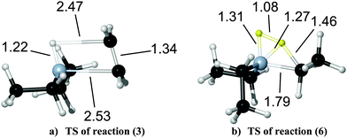 | ||
| Fig. 7 TS structures for reactions (3) and (6) at PBE-D3/def2-TZVPP with selected structural parameters in Å. See Table 1 for reaction numbering. | ||
Besides the uni-molecular reactions, three H2-assisted ethane eliminations have been studied (reactions (6)–(8) in Table 1). They exhibit negative reaction and exothermic Gibbs energies. Electronic barriers are small, while Gibbs energy barriers are significantly higher than the corresponding barriers for β-hydride eliminations. The TS structures are midway between reactants and products (Fig. 7(b) for reaction (6)). The H–H bond is strongly activated (d(H–H) = 1.08 Å versus 0.75 Å in H2), while the B–H-bond length is already rather short (1.31 Å versus 1.21 Å in the product) and the distance of the newly developing C–H-bond is still quite large (1.46 Å versus 1.09 Å in the product). The carbon–boron bond is stretched from 1.55 Å to 1.79 Å. The strong increase of the barrier at higher temperatures can be attributed to a loss of entropy from transferring two flexible reactant molecules to one species with fewer degrees of freedom at the TS.
The reaction energies and barriers evaluated at the MP2 level of approximation are generally in good agreement with the DFT values. Coupled cluster benchmark values at CCSD(T) support the validity of the methodology chosen as outlined previously for TEGa.30 Details can be found in the ESI.†
Gas phase CVD chemistry of TEB
Based on the experimental and computational results outlined above, we now discuss possible gas phase CVD chemistry for TEB. In our previous low temperature CVD study,14 we sketched a chemical reaction mechanism for CVD of BxC films from TEB based on β-hydride elimination of ethylene (C2H4).This reaction was previously reported to occur at 300 °C,16 and thus it was suggested that at temperatures higher than 300 °C, the other two ethyl groups could also be eliminated to form BH3.14 This is in line with the quantum chemical computations in the present study (reactions (3)–(5) in Table 1), which shows the lowest barriers and the most favorable thermodynamic values for this reaction type.
The product distribution under different reaction conditions can now be determined via a list-based KMC simulation based on the full set of reactions. In line with the arguments presented above, only the reactions in Table 1 provide sizeable contributions to the product distributions. Fig. 8 shows the KMC simulations for the reaction catalogue with (Fig. 8(a)) and without (Fig. 8(b)) considering reactions with H2. This simulates the growth in H2 and Ar atmospheres since in the latter case, reactions with H2 is not possible. Both simulations show a rapid decrease of the reactant TEB with increasing temperature, while the intermediates (B(C2H5)2H and B(C2H5)H2) and product (BH3) of the β-hydride elimination reaction are dominant in the gas phase. The importance of β-hydride elimination reactions for the decomposition of group 13 precursors was also found previously for TEGa30 and even for group 15 compounds.37,38 From Table 1, it is found that β-hydride eliminations exhibit moderately high electronic barriers, which increase only slightly with increasing temperature. The H2-assisted ethane eliminations on the other hand show small barriers with a strong increase at higher temperatures due to entropic effects. These reactions should thus only be important at lower temperatures. In Fig. 8(a), the concentration of C2H6 is an indicator for the H2-assisted reactions thus it is present when considering reactions (6)–(8) and absent in Fig. 8(b), which mimics the Ar atmosphere. Thus, the bimolecular reactions contribute to the reaction rate at low temperatures only in the presence of H2.
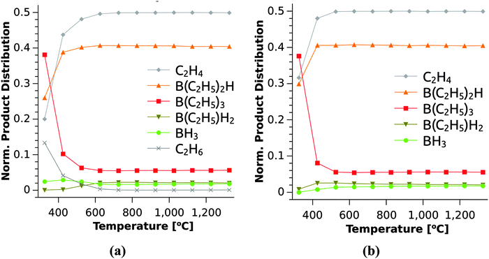 | ||
| Fig. 8 Product distribution derived from KMC simulation under CVD conditions for varying temperatures. Simulation of the full reaction catalogue (a) with (H2 atmosphere) and (b) without (Ar atmosphere) reactions (6)–(8). See Table 1 for reaction numbering. | ||
The origin of C in the deposited films is most likely the C2H4 formed by the β-hydride elimination at all temperatures in the simulation (Fig. 8), or C2H2, which is produced by H2 elimination from C2H4.39 The reactivity of these hydrocarbons is likely low at the lowest temperatures studied giving rise to rather low C contents in the films despite the B/C ratio of 1/6 in the TEB molecule. The gradual increase in C content when the deposition temperature is increased to 1000 °C can be explained by a higher reactivity for the hydrocarbons at higher temperatures.
The C2H6 molecules produced in H2-assisted C2H6 elimination will likely decompose to methyl radicals (˙CH3), by cleaving the C–C single bond,40,41 which would then form CH4 together with the H2 carrier gas. Being the hydrocarbon with the highest symmetry, CH4 is expected to be nonreactive at the lowest deposition temperatures. The formation of less reactive hydrocarbon species together with an increased BH3 formation further explains the significantly higher B/C ratio in films deposited at low temperature in a H2 atmosphere. For deposition at higher temperatures (600 °C < T < 1000 °C) in a H2 atmosphere, C2H4 is mainly formed through β-hydride elimination (Table 1), which is more reactive than CH4, and thus the films are deposited with higher C content, see Fig. 2.
The formation of C2H6 by reactions (6)–(8) is not available in an Ar atmosphere and the TEB molecule is forced to decompose only via β-hydride elimination. Thus, reactive C2H4 is the dominating C-carrying molecule in Ar regardless of deposition temperature (Fig. 8(b)) leading to a more stable B/C ratio with temperature up to 600 °C and increases slightly with the increasing degree of β-hydride elimination at further high temperatures.
Although, the β-hydride elimination is more accessible at higher temperatures, the B content in the films decreases from 700 °C and shows a significant decrease at T > 1000 °C. This is likely caused by the hydrocarbons being more reactive with higher temperatures, leading to more C being deposited. This effect is most clear in a H2 atmosphere, which could be due to the higher B etching on the surface in the presence of H2 carrier gas, which is not the case in an Ar atmosphere (see Fig. 2).
CVD of BN using TEB as a boron precursor is typically done in a H2 atmosphere at temperatures above 1000 °C and from our results it can be concluded that at this temperature at least one, likely more than one, of the ethyl groups on TEB is eliminated by β-hydride elimination. The boron species active for BN formation are thus BH3, B(C2H5)H2 and B(C2H5)2H. The problem one faces when using TEB for CVD of BN is the formation of the hydrocarbons as by-products. The incorporation of carbon into BN is unwanted and a significant risk at temperatures above 1000 °C is shown by our results. The CVD chemistry (both gas phase- and surface chemistry) of the nitrogen precursor, typically NH3, is crucial for the formation of a BN instead of a boron carbide or a boron carbonitride.
Conclusions
From our results we conclude that the gas phase CVD chemistry of TEB is dominated by β-hydride eliminations of C2H4 to finally yield BH3 (reactions (3)–(5)). C2H4 is at least partly expected to undergo H2 elimination to C2H2 and it is thus likely that BH3, C2H4 and C2H2 are the active species for the deposition of BxC. In a H2 atmosphere, a H2-assisted C2H6 elimination path to BH3 (reactions (6)–(8)) can be of importance at lower temperatures. The formed C2H6 is expected to decompose to methyl radicals, which subsequently forms methane with hydrogen. The low reactivity of CH4 at low temperatures leads to very B-rich films. We also find that CVD of BxC thin films using TEB as a single-source precursor produces X-ray amorphous films with 2.5 ≤ x ≤ 4.5 and low H content in a temperature range of 600–1000 °C in both H2 and Ar atmospheres. Depositions at lower temperatures result in high H incorporation while higher temperatures in C-rich films. The quantum chemical calculations produced a comprehensive reaction catalogue for the gas phase chemistry of TEB including thermochemical data under CVD conditions.Acknowledgements
Financial support from European Spallation Source ESS AB, the Knut and Alice Wallenberg Foundation, the German Science Foundation (Research Training Group 1782) and the Beilstein Foundation (Frankfurt/Germany) is gratefully acknowledged. The authors would like to acknowledge the Tandem Laboratory at Uppsala University for giving access to their ion beam facilities and Dr Lina Rogström is acknowledged for her help with nanoindentation measurements and useful discussions. We also thank the HRZ Marburg for computational resources.References
- J. C. Oliveira, M. N. Oliveira and O. Conde, Surf. Coat. Technol., 1996, 80, 100–104 CrossRef CAS.
- K.-W. Lee and S. J. Harris, Diamond Relat. Mater., 1998, 7, 1539–1543 CrossRef CAS.
- M. Bouchacourt and F. Thevenot, J. Less-Common Met., 1981, 82, 219–226 CrossRef CAS.
- M. Chubarov, H. Pedersen, H. Högberg, S. Filippov, J. A. A. Engelbrecht, J. O'Connel and A. Henry, Phys. B, 2014, 439, 29–34 CrossRef CAS PubMed.
- A. Geim and I. V. Grigorieva, Nature, 2013, 499, 419–425 CrossRef CAS PubMed.
- C. Höglund, J. Birch, K. Andersen, T. Bigault, J. C. Buffet, J. Correa, P. Van Esch, B. Guerard, R. Hall-Wilton, J. Jensen, A. Khaplanov, F. Piscitelli, C. Vettier, W. Vollenberg and L. Hultman, J. Appl. Phys., 2012, 111, 104908 CrossRef PubMed.
- J. Li, R. Dahal, S. Majety, J. Y. Lin and H. X. Jiang, Nucl. Instrum. Methods Phys. Res., Sect. A, 2011, 654, 417–420 CrossRef CAS PubMed.
- K. Andersen, T. Bigault, J. Birch, J. C. Buffet, J. Correa, R. Hall-Wilton, L. Hultman, C. Höglund, B. Guérard, J. Jensen, A. Khaplanov, O. Kirstein, F. Piscitelli, P. Van Esch and C. Vettier, Nucl. Instrum. Methods Phys. Res., Sect. A, 2013, 720, 116–121 CrossRef CAS PubMed.
- D. Kramer, Phys. Today, 2011, 64, 20–23 CrossRef PubMed.
- U. Jansson, J.-O. Carlsson, B. Stridh, S. Söderberg and M. Olsson, Thin Solid Films, 1989, 172, 81–93 CrossRef CAS.
- A. Pakdel, Y. Bando and D. Golberg, Chem. Soc. Rev., 2014, 43, 934–959 RSC.
- CRC Handbook of Chemistry and Physics, ed. W. M. Haynes, CRC Press, Boca Raton, FL, 95th edn, 2014, pp. 3–526 Search PubMed.
- National Institute of Standards and Technology (NIST) Webbook: http://webbook.nist.gov/cgi/cbook.cgi?ID=C97949&Mask=1A8F, accessed 2015–05–25.
- H. Pedersen, C. Höglund, J. Birch, J. Jensen and A. Henry, Chem. Vap. Deposition, 2012, 18, 221–224 CrossRef CAS PubMed.
- M. Chubarov, H. Pedersen, H. Högberg, J. Jensen and A. Henry, Cryst. Growth Des., 2012, 12, 3215–3220 CAS.
- J. S. Lewis, S. Vaidyaraman, W. J. Lackey, P. K. Agrawal, G. B. Freeman and E. K. Barefield, Mater. Lett., 1996, 27, 327–332 CrossRef CAS.
- A. Henry, J. Hassan, J. P. Bergman, C. Hallin and E. Janzén, Chem. Vap. Deposition, 2006, 12, 475–482 CrossRef CAS PubMed.
- J. Jensen, D. Martin, A. Surpi and T. Kubart, Nucl. Instrum. Methods Phys. Res., Sect. B, 2010, 268, 1893–1898 CrossRef CAS PubMed.
- H. J. Whitlow, G. Possnert and C. S. Petersson, Nucl. Instrum. Methods Phys. Res., Sect. B, 1987, 27, 448–457 CrossRef.
- J. Perdew, K. Burke and M. Ernzerhof, Phys. Rev. Lett., 1996, 77, 3865–3868 CrossRef CAS.
- S. Grimme, J. Antony, S. Ehrlich and H. Krieg, J. Chem. Phys., 2010, 132, 154104 CrossRef PubMed.
- S. Grimme, S. Ehrlich and L. Goerigk, J. Comput. Chem., 2011, 32, 1456–1465 CrossRef CAS PubMed.
- F. Weigend and R. Ahlrichs, Phys. Chem. Chem. Phys., 2005, 7, 3297–3305 RSC.
- R. Ahlrichs, Phys. Chem. Chem. Phys., 2004, 6, 5119–5121 RSC.
- M. Sierka, A. Hogekamp and R. Ahlrichs, J. Chem. Phys., 2003, 118, 9136–9148 CrossRef CAS PubMed.
- Turbomole, 6.6, 2014, a development of University of Karlsruhe and Forschungszentrum Karlsruhe GmbH, 1989–2007, Turbomole GmbH, since 2007; available from http://www.turbomole.com.
- M. J. Frisch, G. W. Trucks, H. B. Schlegel, G. E. Scuseria, M. A. Robb, J. R. Cheeseman, G. Scalmani, V. Barone, B. Mennucci, G. A. Petersson, H. Nakatsuji, M. Caricato, X. Li, H. P. Hratchian, A. F. Iz-maylov, J. Bloino, G. Zheng, J. L. Sonnenberg, M. Hada, M. Ehara, K. Toyota, R. Fukuda, J. Hasegawa, M. Ishida, T. Nakajima, Y. Honda, O. Kitao, H. Nakai, T. Vreven, J. A. Montgomery, Jr., J. E. Peralta, F. Ogliaro, M. Bearpark, J. J. Heyd, E. Brothers, K. N. Kudin, V. N. Staroverov, R. Kobayashi, J. Normand, K. Raghavachari, A. Rendell, J. C. Burant, S. S. Iyengar, J. Tomasi, M. Cossi, N. Rega, J. M. Millam, M. Klene, J. E. Knox, J. B. Cross, V. Bakken, C. Adamo, J. Jaramillo, R. Gomperts, R. E. Stratmann, O. Yazyev, A. J. Austin, R. Cammi, C. Pomelli, J. W. Ochterski, R. L. Martin, K. Morokuma, V. G. Zakrzewski, G. A. Voth, P. Salvador, J. J. Dannenberg, S. Dapprich, A. D. Daniels, Ö. Farkas, J. B. Foresman, J. V. Ortiz, J. Cioslowski and D. J. Fox, Gaussian09 (Revision C.01), Gaussian Inc., Wallingford, CT, 2009 Search PubMed.
- J. J. P. Stewart, J. Mol. Model., 2007, 13, 1173–1213 CrossRef CAS PubMed.
- C. Peng, P. Ayala, H. B. Schlegel and M. J. Frisch, J. Comput. Chem., 1996, 17, 49–56 CrossRef CAS.
- A. Stegmüller, P. Rosenow and R. Tonner, Phys. Chem. Chem. Phys., 2014, 16, 17018–17029 RSC.
- H. P. Hratchian and H. B. Schlegel, J. Chem. Theory Comput., 2005, 1, 61–69 CrossRef CAS.
- O. Sackur, Ann. Phys., 1911, 36, 958–980 CrossRef PubMed.
- L.-O. Björketun, L. Hultman, I. P. Ivanov, Q. Wahab and J.-E. Sundgren, J. Cryst. Growth, 1997, 182, 379–388 CrossRef.
- Joint Committee on Powder Diffraction Standards, JCPDS, Swarthmore, PA, PDF card no. 00-056-0159.
- Joint Committee on Powder Diffraction Standards, JCPDS, Swarthmore, PA, PDF card no. 00-029-1129.
- O. Knotek, E. Lugscheider and C. W. Siry, Surf. Coat. Technol., 1997, 91, 167–173 CrossRef CAS.
- A. Stegmüller and R. Tonner, Inorg. Chem., 2015, 54, 6363–6372 CrossRef PubMed.
- A. Stegmüller and R. Tonner, Chem. Vap. Deposition, 2015, 21, 161–165 CrossRef PubMed.
- C. D. Stinespring and J. C. Wormhoudt, J. Cryst. Growth, 1988, 87, 481–493 CrossRef CAS.
- G. M. Petrov and J. L. Giuliani, J. Appl. Phys., 2001, 90, 619–636 CrossRef CAS PubMed.
- W. Tsang and R. F. Hampson, J. Phys. Chem. Ref. Data, 1986, 15, 1087–1279 CrossRef CAS PubMed.
Footnote |
| † Electronic supplementary information (ESI) available: Tables with more details of the atomic content and measured densities and hardness of the films, and more details of the computations together with Cartesian coordinates of structures. See DOI: 10.1039/c5tc02293b |
| This journal is © The Royal Society of Chemistry 2015 |

