 Open Access Article
Solid solution magnetic FeNi nanostrand–polymer composites by connecting-coarsening assembly†
Stephan
Barcikowski
a,
Thomas
Baranowski
a,
Yigit
Durmus
a,
Ulf
Wiedwald
b and
Bilal
Gökce
*a
aInstitute of Technical Chemistry I, and Center for Nanointegration Duisburg-Essen (CENIDE), University of Duisburg-Essen, 45141 Essen, Germany. E-mail: bilal.goekce@uni-due.de
bFaculty of Physics, and Center for Nanointegration Duisburg-Essen (CENIDE), University of Duisburg-Essen, 47057 Duisburg, Germany
First published on 3rd September 2015
Abstract
An approach to assemble high aspect ratio nanostrands consisting of magnetic nanowires and their incorporation in a polymer with the aim of tailoring transparent FeNi nanostrand–PMMA-composites is presented. These nanostrands are controllable in length (<600 μm) and width (<12 μm) via process parameters and have an ultra-high aspect ratio (∼160). This rapid and universal method provides flexible and transparent magnetic materials with tunable transparency and magnetic attraction force by adjusting the density of nanoparticles in the composite. These composites can be used as a window coating for shielding radio frequency electromagnetic waves while being transparent in the optical range.
1. Introduction
Inorganic nanoparticle polymer composites possess remarkable and unique properties, precisely combining properties of their individual constituents thus opening innovative possibilities for scientific and industrial applications. Consequently the modification and improvement of materials by incorporating nanoparticles has been gaining extensive attention over the last years.1 Applications range from hardening, flammability resistance to antimicrobial surfaces, drug delivery applications, fuel cells, electronics and photovoltaics. The addition of nanoparticles to the polymer matrix leads to a change of the glass transition temperature, the crystallization rate and the degree of crystallinity, which affect the properties of the composite in an essential way. In addition, unique chemical, biological, optical, electronic and magnetic properties of nanoparticles are transferred to the polymer system. While many researchers focused on polymers embedded with isotropic nanomaterials,2 very recently nanomaterials with magnetic high aspect ratio have begun to receive attention because of their suitability for magnetic separation and manipulation, magnetic resonance imaging applications,3 and rare earth free permanent magnets.4 The aspect ratio is defined as the relative relationship between the major axis and the minor axis of an object. Beside nanotubes and nanorods, nanowires are the most prominent nanomaterials with an aspect ratio much larger than 1. Methods to assemble nanoparticles to nanowires in a polymer include zero-field self-assembly or magnetic-field-induced-assembly (MFIA).5 MFIA represents a unique and therefore widely exploited route due to the instantaneous and anisotropic nature of magnetic interactions.6 Hence it has been widely used to form nanowires which have been utilized in materials fabrication and the design of functional devices in many fields.7 Most common building blocks of these nanowires are iron oxides such as α-Fe2O3,8 γ-Fe2O3,9 and Fe3O4.10 A novel approach where MFIA is used in combination with laser ablation was reported by Liang et al. The authors performed magnetic field-assisted ns-laser ablation of bulk FeNi in ethanol to form one-dimensional FeNi-nanowires in the solvent.11–13Until now, the longest nanowires embedded in a polymer were formed by Fragouli et al. measuring 15 μm at a thickness of 200 nm.14 However, these composites were optically not transparent due to the relatively high filling factor of Fe2O3 nanoparticles of 1–5 wt% in poly(ethylmethacrylate-co-methylacrylate).
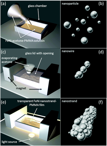
In this study, we demonstrate the fabrication of highly-transparent nanocomposites consisting of FeNi-wires (Fig. 1d) that are assembled into FeNi-nanostrands (Fig. 1f). Nanostrands such as Ni-nanostrands can be used in shape memory polymers to improve the electrical and thermal conductivity of the composite as shown by Lu et al.15,16 However, there is limited literature on the size-control of nanostrands. Here, we show the synthesis of FeNi-nanostrands that are controllable in length and thickness; 5–400 nm particles forming strands up to 600 μm in length are demonstrated and embedded in a polymer to obtain a composite with a transparency of >75%. The limited strand-length in previous literature is overcome by using picosecond-laser-generated nanoparticles, which have a bimodal volume distribution17 (Fig. S1, ESI†), achieving aspect ratios of 50–160.
2. Results and discussion
In the following sections, the experimental approach to produce transparent ultrahigh aspect ratio solid FeNi nanostrand–polymer composites is described. The results demonstrate control over the nanostrand length and width. Further the magnetic properties of the nanoparticles and FeNi–PMMA composites are characterized.2.1. Preparation of FeNi–PMMA-composites
The nanocomposites are prepared by solvent drying from casted solutions of FeNi nanoparticle–poly(methylmethacrylate) (PMMA) in acetone, under a magnetic field (Fig. 1). For our given geometry the magnetic field is 150 mT along the composite as measured by a Hall probe teslameter.First the solution containing disordered nanoparticles (Fig. 1b) is poured into a custom-made glass chamber, which is subsequently closed with a lid. In order to obtain a good transparency the solvent needs to be evaporated in a controlled way, this is achieved by an opening on top of the closed chamber. In contrary to the literature14 where 1–5 wt% are required, nanoparticle concentrations as low as 0.025 wt% suffice to form reproducible nanowires (Fig. 1d) within the polymer. Here, we demonstrate formation and control of the longest nanostrands (Fig. 1f) with nanoparticle concentrations of 0.025 wt%, 0.100 wt% and 0.400 wt% with respect to the final polymer composite. This low filling factor results in transparent polymers, which transmit 75–97% of the visible light. The required amount of dissolved PMMA in acetone depends on the strength of the applied magnetic field and is chosen to be 1 wt% in our experiments. The amount of PMMA has to be increased when the strength of the magnetic field is increased. The casted solution is dried in a magnetic field of 150 mT. After a certain amount of time the magnet is removed which determines the length of the nanostrand. Pure PMMA is a relatively flexible polymer with a flexural modulus of 1880 MPa,18 upon inspection the produced composite retains its flexibility even if the nanoparticle filling factor is increased up to 1 wt% as shown in Fig. S5c, ESI.†
The employed nanoparticles are peculiar in that they are nanoalloys with a Fe/Ni atomic ratio of 1![[thin space (1/6-em)]](https://www.rsc.org/images/entities/char_2009.gif) :
:![[thin space (1/6-em)]](https://www.rsc.org/images/entities/char_2009.gif) 1 (Fig. S2, ESI†) and that they have a bimodal volume distribution with peaks at 60 nm and 190 nm (Fig. S1, ESI†). In comparison with conventional magnetic materials, such as iron oxides or Ni, the nanoparticles of binary 3d transition metal alloys are found to have considerably larger saturation magnetization.19,20
1 (Fig. S2, ESI†) and that they have a bimodal volume distribution with peaks at 60 nm and 190 nm (Fig. S1, ESI†). In comparison with conventional magnetic materials, such as iron oxides or Ni, the nanoparticles of binary 3d transition metal alloys are found to have considerably larger saturation magnetization.19,20
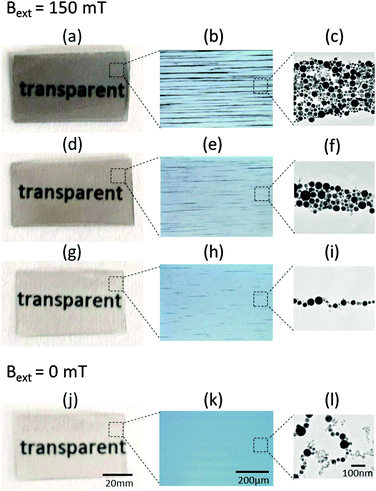
The broad and bimodal volume distribution of picosecond-laser-generated nanoparticles leads to an unprecedented control over the formation of nanostrands within polymers. Fig. 2 shows the results for fabricated composites with 3 different filling factors.
It is evident that very long and thick nanostrands embedded in a polymer can be assembled with a bimodal nanoparticle size distribution. Fig. 2b shows 600 μm long nanostrands embedded in a polymer matrix while Fig. 2c displays how different sizes of surfactant-free nanoparticles assemble in an applied magnetic field of 150 mT forming a 600 nm thick strand. The transparency of the composites is measured by UV-VIS extinction spectroscopy and found to be 91%, 84% and 75% at a wavelength of 660 nm for filling factors of 0.025 wt%, 0.100 wt% and 0.400 wt%, respectively. The transparency does not change when the magnetic field (hence the length of the nanostrands) is decreased from 150 mT to 30 mT at a constant filling factor (data not shown). These results demonstrate that very long nanostrands can be homogenously dispersed and well aligned into a polymer without losing its transparency which is solely determined by the filling factor. Fig. 2j–l show the control experiment for the 0.025 wt% specimen in the absence of an external magnetic field. While magnetic particles clearly show dipolar interaction no preferential orientation is observed. In order to test the transferability of our method we performed control experiments with a different polymer solution (FeNi in Polycarbonate/THF) as well as experiments with different nanoparticles (AuFe in PMMA/acetone, Fig. S6, ESI†). Both systems lead to the formation of transparent composites containing ∼100 μm-nanostrands confirming that this method is not limited to the nanoparticle–polymer-combination described here.
2.2. Control of nanostrand length and width
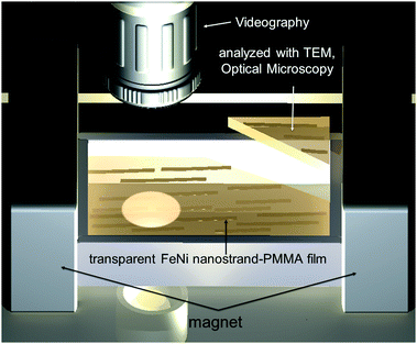
Control of the nanostrand length and width is achieved by varying the application time of the magnetic field during the solvent evaporation. Moreover the polymer concentration plays a crucial role for the dimensions of the formed strands. The time evolution is measured by videography, optical and TEM microscopy as shown in Fig. 3.Due to the resolution limits of an optical microscope the first 20 seconds of strand formation cannot be recorded by videography; hence TEM is used to image the initial stages of the strand formation.
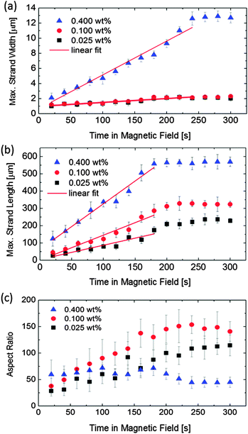
Fig. 4b shows the evolution of the maximum strand length with time. The strand length is increasing with higher concentration of nanoparticles in the polymer. While strands with a length of 230 μm can be achieved with a filling factor of 0.025 wt% after 300 s in the magnetic field, 570 μm long strands are obtained with a 16 fold increase of the nanoparticle concentration. Interestingly, saturation of the maximum strand length is reached after 180 seconds independent of the filling factor. Until the saturation point is reached we observe a linear increase of the maximum strand length with time. The intercepts of the linear regressions agree well with the chain length during self-assembly without the presence of a magnetic field of the nanoparticles at the given concentration (compare with Fig. S4, ESI†).
Fig. 4a quantifies the control over the maximum strand width. Apparently, the maximum strand length reaches a limit after application of the magnetic field for 200–250 seconds. Similar to the maximum strand length the saturation is preceded by a linear increase. Here all intercepts of the linear regressions for different filling factors coincide at a value of approx. 400 nm which is in turn the particle size of the largest nanoparticles within the solution as measured by dynamic light scattering (Fig. S1, ESI†).
The highest aspect ratio, a ratio of approx. 160, is obtained for the strand assembled with 0.1 wt% nanoparticle content (Fig. 4c, red curve). This is to the best of our knowledge the highest aspect ratio achieved for a strand consisting of nanoparticles. With a higher filling factor (e.g. 0.4 wt%) the aspect ratio cannot be further increased, it is not even changing during the time the magnetic field is applied. Since the literature describes composites with filling factors over 1 wt%, this observation might explain why such high aspect ratios have not been observed until now.
The formation mechanism of the strands is analog to the mechanism described by Fang et al.21 The authors describe two basic mechanisms, namely connection and coarsening, that take place during the curing of an Fe3O4 magnetic fluid and a polymer acrylic resin. We observe the same mechanisms as shown in Fig. 5 (also available as a Video in the ESI†).
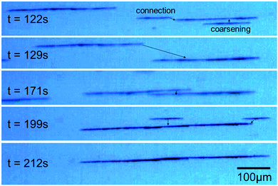 | ||
| Fig. 5 Assembly of a ∼600 μm long strand by connection and coarsening mechanism as captured by videography (video is available in the ESI†). Images at times in the magnetic field t = 122 s, 129 s, 171 s, 199 s and 212 s are shown for a nanoparticle filling factor of 0.4 wt%. Arrows indicate the docking positions of initially separated strands forming a single strand with time. | ||
The nanostrand formation is considered as the result of the competition of the magnetic attraction, the surface energy and the entropic contribution of small nanowires.22
When the external magnetic field is absent, particle aggregation as a result of Brownian motion and dipolar interaction between the particles leads to the formation of ∼1 μm long wire structures (Fig. 2l and Fig. S4, ESI†). These wires are then oriented along the external magnetic field and eventually used to form strands. Due to the lower potential energy of a particle located near the end of a wire, particles tend to connect at the end of the wires, which explains the scalability of the strand length observed in Fig. 4b. Also, the identical curves in Fig. 4a for the maximum width of the strand within a composite with 0.100 wt% and 0.025 wt% FeNi nanoparticles can be explained. When a higher nanoparticle concentration is present, the potential energy barrier of long wires can be overcome, thus coarsening preferably takes place. Apparently, this is the case for a filling factor between 0.1 wt% and 0.4 wt%.
Nanostrands assembled with nanoparticles of a broad monomodal volume distribution (Fig. S7, ESI†) indicate that a bimodality favors the assembly of longer strands. With a bimodal volume distribution as used for our strand-assembly even longer strands (>1 mm) are possible with higher nanoparticle concentrations within the polymer matrix as shown in the ESI† (Fig. S5d) for a filling factor of 1 wt%. However in this case the transparency of the composite for visible light is dramatically decreased (Fig. S5a, ESI†).
2.3. Characterization of FeNi nanoalloys and nanocomposites
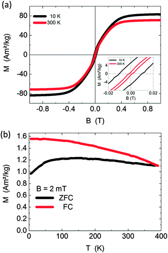
The building blocks (i.e. FeNi nanoalloys) of the nanostrands are investigated in more detail in order to understand their influence on the formation mechanism. XRD measurements (Fig. S3, ESI†) of the laser-generated nanoalloys reveal that the main phases consist of the hexagonal structure of FeNi and the cubic structure of FeNi3similar to what has been reported in the literature for laser-generated nanoparticles.13 Magnetic hysteresis loops of the nanoalloys are measured at ambient temperature (300 K) and low temperature (10 K) as shown in Fig. 6(a).The hysteresis loops indicate ferromagnetic properties for FeNi nanoparticles. The saturation magnetizations of the sample are measured to be 72 A m2 kg−1 and 83 A m2 kg−1 at 300 K and 10 K, respectively. The enlarged plots show a very small coercivity (2 mT and 10 mT) and low remanent magnetization (0.7 and 5 A m2 kg−1).
Zero-field cooled (ZFC) and field cooled (FC) magnetization curves measured in an applied field of 2 mT for FeNi nanoparticles are displayed in Fig. 6(b). The broad ZFC maximum with a plateau between 100 K and 200 K reflects the broad size distribution of nanoparticles (Fig. S1, ESI†). While smaller nanoparticles get superparamagnetic well below ambient temperature, the larger nanoparticles remain ferromagnetic up the highest temperature T = 390 K as indicated by the gradual decrease of both, ZFC and FC curves. At higher temperatures, however, the applied field of 2 mT may overcome the coercive field of the larger particles as suggested by the hysteresis loop at T = 300 K. As shown before, the magnetostatic interaction energy is several orders of magnitude larger than the thermal energy for the present particle sizes at ambient temperature.14 Thus, the larger particles produce a significant stray field and capture the smaller particles along their magnetization axis forming chaotic arrangements as shown in Fig. 2l. A homogeneous external field introduces a preferred orientation of the nanostrands.
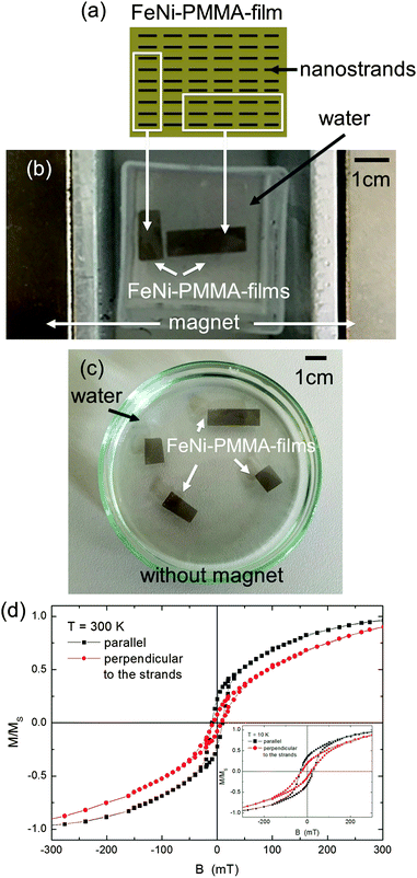
Fig. 7 demonstrates the effect of an external magnetic field on the produced composites. Two pieces from a FeNi–PMMA-film that contain nanostrands aligned horizontally are cut as indicated by the white squares in Fig. 7a. Fig. 7b shows the oriented response of these two differently-cut pieces to a magnetic field. Independent on the shape of the composite, both pieces align with the nanostrand long axis parallel the external magnetic field. In-plane magnetic hysteresis loops measured parallel and perpendicular further support the anisotropy introduced into the samples. Fig. 7d presents the experimental data for the 0.1 wt% sample. The hysteresis loops show enhanced coercive fields of 10 mT (7 mT) at T = 300 K and 29 mT (22 mT) at T = 10 K for parallel (perpendicular) orientation as compared to the powder sample (Fig. 6). This is due to the orientation of anisotropy axes by the formation of the nanostrands. The sample reaches its saturation magnetization at 500 mT that is similar to the powder sample. Most important is the different magnetization behavior for parallel and perpendicular geometries proving that the nanostrands are easier to magnetize in parallel geometry due to their larger dipolar coupling.
3. Experimental
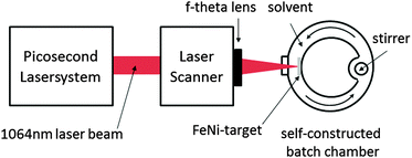
3.1. Synthesis of FeNi-nanoalloys by ultrashort laser ablation in liquids
Fe–Ni-nanoalloys are produced by ultrashort laser ablation in liquids (Fig. 8).23,24A Nd:YAG laser (Ekspla, Atlantic) with a pulse duration of 10 ps, a repetition rate of 100 kHz, a pulse energy of 156 μJ and a laser wavelength centered at 1064 nm is used. The laser beam is directed in a laser scanner and focused with an f-theta lens (focal length of 100.1 mm) on the FeNi-target (50–50%, Sekels) which is placed in acetone (99.5%) in a self-constructed stirred batch chamber. The liquid layer over the target measures 6 mm. The obtained FeNi–acetone-colloid is used for further processing as shown in Fig. 1a.
3.2. Characterization
The morphology and microstructure of the samples were characterized by videography (Altra 20), TEM (Philips, CM12), SEM-EDS (ESEM Quanta 400 FEG) and optical microscopy (Olympus, CX40). Magnetometry was conducted in a Quantum Design PPMS DynaCool and a MPMS system.4. Conclusions
In conclusion, we have demonstrated the preparation of transparent and magnetically anisotropic FeNi nanostrand–PMMA-composites that contain nanostrands with aspect ratios as high as 160. Following the connection-coarsening-mechanism we were able to time-resolve the formation dynamics of these strands. FeNi-nanostrands as long as 600 μm were formed using magnetic-field-induced-assembly and exploiting the bimodal volume distribution of picosecond-laser-generated nanoparticles in solidifying polymer solution. These magnetic alloy nanostrands were homogenously embedded into a PMMA-polymer-matrix without any matrix coupling additives and led to a transparent composite. The dimensions of the nanostrands were controllable by the application time of the magnetic field and the nanoparticle concentration. Additionally the transferability of our method to other nanoparticle–polymer systems was shown. As a potential application the anisotropic composite might be used as a window coating for shielding radio frequency electromagnetic waves while being transparent in the optical range.Acknowledgements
We acknowledge Michael Farle for helpful discussions, Dongshi Zhang for the TEM images.References
- S. Srivastava, J. L. Schaefer, Z. Yang, Z. Tu and L. A. Archer, Adv. Mater., 2014, 26, 201 CrossRef CAS PubMed.
- A. C. Balazs, T. Emrick and T. P. Russell, Science, 2006, 314, 5802 CrossRef PubMed.
- R. M. Fratila, S. Rivera-Fernández and J. M. de la Fuente, Nanoscale, 2015, 7, 8233 RSC.
- S. Liébana-Viñas, U. Wiedwald, A. Elsukova, J. Perl, B. Zingsem, A. S. Semisalova, V. Salgueirino, M. Spasova and M. Farle, Chem. Mater., 2015, 27, 4015 CrossRef.
- L. He, M. Wang, J. Ge and Y. Yin, Acc. Chem. Res., 2012, 45, 1431 CrossRef CAS PubMed.
- M. Wang, L. He and Y. Yin, Mater. Today, 2013, 16, 110 CrossRef CAS PubMed.
- Y. Hu, L. He and Y. Yin, Angew. Chem., Int. Ed., 2011, 50, 3747 CrossRef CAS PubMed.
- L. Meng, W. Chen, C. Chen, H. Zhou, Q. Peng and Y. Li, Cryst. Growth Des., 2010, 10, 479 CAS.
- S. Palchoudhury, Y. Xu, J. Goodwin and Y. Bao, J. Appl. Phys., 2011, 109, 07E314 CrossRef PubMed.
- H. Wang, Q. Chen, L. Sun, H. Qi, X. Yang, S. Zhou and J. Xiong, Langmuir, 2009, 25, 7135 CrossRef CAS PubMed.
- Y. Liang, P. Liu, J. Xiao, H. Li, C. Wang and G. W. Yang, Sci. Rep., 2013, 3, 3051 Search PubMed.
- Y. Liang, P. Liu, J. Xiao, H. B. Li, C. X. Wang and G. W. Yang, Laser Phys. Lett., 2014, 11, 056001 CrossRef.
- Y. Liang, P. Liu and G. W. Yang, Cryst. Growth Des., 2014, 14, 5847 CAS.
- D. Fragouli, R. Buonsanti, G. Bertoni, C. Sangregorio, C. Innocenti, A. Falqui, D. Gatteschi, P. D. Cozzoli, A. Athanassiou and R. Cingolani, ACS Nano, 2010, 4, 1873 CrossRef CAS PubMed.
- H. Lu, F. Liang and J. Gou, Soft Matter, 2011, 7, 7416 RSC.
- H. Lu, et.al., Smart Mater. Struct., 2011, 20, 035017 CrossRef.
- C. Rehbock, J. Jakobi, L. Gamrad, S. Meer, D. Tiedemann, U. Taylor, W. Kues, D. Rath and S. Barcikowski, Beilstein J. Nanotechnol., 2014, 5, 1523 CrossRef PubMed.
- M. Avella, M. E. Errico and E. Martuscelli, Nano Lett., 2001, 1, 213 CrossRef CAS.
- Y. Xie and J. A. Blackman, Phys. Rev. B: Condens. Matter Mater. Phys., 2002, 66, 085410 CrossRef.
- G. Mpourmpakis, G. E. Froudakis, A. N. Andriotis and M. Menon, Phys. Rev. B: Condens. Matter Mater. Phys., 2005, 72, 104417 CrossRef.
- W. Fang, Z. He, X. Xu, Z. Mao and H. Shen, Europhys. Lett., 2007, 77, 68004 CrossRef.
- F. M. Ytreberg and S. R. McKay, Phys. Rev. E: Stat. Phys., Plasmas, Fluids, Relat. Interdiscip. Top., 2000, 61, 4107 CrossRef CAS.
- B. Gökce, D. van't Zand, A. Menéndez-Manjón and S. Barcikowski, Chem. Phys. Lett., 2015, 626, 96 CrossRef PubMed.
- J. Jakobi, S. Petersen, A. Menendez-Manjon, P. Wagener and S. Barcikowski, Langmuir, 2010, 26, 6892 CrossRef CAS PubMed.
Footnote |
| † Electronic supplementary information (ESI) available: Particle size distribution of laser-generated nanoparticles as measured by dynamic light scattering, EDS measurement of nanoalloys, video showing the formation mechanism of nanowires. See DOI: 10.1039/c5tc02160j |
| This journal is © The Royal Society of Chemistry 2015 |

