 Open Access Article
A flexible high-sensitivity piezoresistive sensor comprising a Au nanoribbon-coated polymer sponge†
Xiuxiu
Yin
a,
T. P.
Vinod
a and
Raz
Jelinek
*ab
aDepartment of Chemistry, Ben Gurion University of the Negev, Beer Sheva 84105, Israel. E-mail: razj@bgu.ac.il
bIlse Katz institute for Nanotechnology, Ben Gurion University of the Negev, Beer Sheva 84105, Israel
First published on 20th July 2015
Abstract
Development of pressure sensors which display high sensitivity, and are flexible, inexpensive, and easy to manufacture has drawn significant interest due to their diverse applications such as tactile skin sensors (e.g. “electronic skin”), pulse detectors, speech recognition elements, and others. While varied technologies and molecular constructs have been demonstrated for pressure sensing, considerable conceptual and technical challenges still hamper broad implementation of many such systems. A novel flexible piezoresistive sensor comprising a conductive Au-coated elastomeric polymer sponge is presented. The piezoresistive sponge is prepared through a simple chemical route in which Au nanoribbons are spontaneously grown upon an amine-functionalized polyurethane framework. The Au nanoribbon layer coats the internal surfaces within the polymer pore network, resulting in electrical current modulation upon pressure application/release through changes in the overall contact areas between the conductive surfaces. The Au-polyurethane piezoresistive sensor exhibits excellent functionalities, including enhanced sensitivity, low detection threshold, high fidelity, and physical stability. Application of the sensor is demonstrated for high resolution monitoring of wrist arterial pulses.
Introduction
Sensitive, easy to manufacture, and inexpensive pressure sensors have considerable scientific, technological, and commercial impact as they are used in many practical applications and devices, such as tactile skin sensors (e.g. “electronic skin”), speech recognition elements, and others.1–8 Varied molecular systems and technologies have been developed for pressure sensing including field effect transistor devices,9–12 capacitance-based sensing,13–15 piezoelectric sensing,16–23 and piezoresistive sensing.24–27 Nevertheless, considerable technical challenges still exist. Specifically, in many instances, sensing devices exhibit complex design and/or elaborate, expensive manufacturing routes, limiting the practical and commercial potential.Elastomeric polymers coupled with conductive elements have been recently shown to constitute useful platforms for chemically-based pressure sensors.28–30 Such assemblies rely on the intrinsic flexibility of the polymer frameworks to produce piezoresistive sensors in which the compression/release of the matrix modulates the electrical resistance.31–33 Porous polymers or “sponges” have been particularly attractive in that regard since such materials provide readily utilized and inexpensive host matrices for embedding the conductive layers.34,35 Pressure sensors based on elastomeric polymer sponges encapsulating carbon nanotubes,36 graphene,37 or metals38–40 have been reported. However, despite the promise of such “bottom-up” strategies, pressure sensors constructed through such schemes have displayed in many cases relatively low sensitivity, and their production generally comprise of multistep and complex chemical processes.
We present a novel, sensitive piezoresistive sensor comprising a conductive Au-coated elastomeric polymer sponge. The piezoresistive sponge was prepared through a simple two-step chemical route based on the self-assembly of Au nanoribbon thin films onto an amine-functionalized polyurethane (PU) framework. The Au–PU piezoresistive sensor exhibited excellent pressure sensing parameters, including low detection threshold, signal reproducibility, and physical stability. We demonstrate the application of the sensor for monitoring and waveform analysis of wrist arterial pulses.
Experimental section
Materials
HAuCl4·3H2O, KSCN, branched polyethylenimine (b-PEI) with average Mw ∼ 25![[thin space (1/6-em)]](https://www.rsc.org/images/entities/char_2009.gif) 000 by LS average Mn ∼ 10
000 by LS average Mn ∼ 10![[thin space (1/6-em)]](https://www.rsc.org/images/entities/char_2009.gif) 000 by GPC, N-hydroxysuccinimide (NHS), 2-(N-morpholino)ethane sulfonic acid (MES) and conductive silver paint were purchased from Sigma-Aldrich. H2SO4 was purchased from Bio Lab (Israel). 1-(3-Dimethylaminopropyl)-3-ethylcarbodiimide (EDC) 98% and chromium trioxide were purchased from Alfa Aesar (USA). All above listed reagents were used as received. Water used in the experiments was doubly purified using a Barnstead D7382 water purification system (Barnstead Thermolyne, Dubuque, IA), at 18.3 mΩ cm resistivity.
000 by GPC, N-hydroxysuccinimide (NHS), 2-(N-morpholino)ethane sulfonic acid (MES) and conductive silver paint were purchased from Sigma-Aldrich. H2SO4 was purchased from Bio Lab (Israel). 1-(3-Dimethylaminopropyl)-3-ethylcarbodiimide (EDC) 98% and chromium trioxide were purchased from Alfa Aesar (USA). All above listed reagents were used as received. Water used in the experiments was doubly purified using a Barnstead D7382 water purification system (Barnstead Thermolyne, Dubuque, IA), at 18.3 mΩ cm resistivity.
Synthesis of the KAu(SCN)4 complex
1 mL of an aqueous solution of HAuCl4·3H2O (24 mg mL−1) was added to 1 mL of a solution of KSCN in water (60 mg mL−1). The precipitate formed was separated by centrifugation at 4000g for 10 min. The supernatant was decanted, and the residue was dried at room temperature.Amine modification and fiber fracture of the PU sponges
A commercially available PU sponge (average pore size 0.1–0.3 mm; porosity of around 93%) was cut into cuboids and cleaned in deionized water (DIW), ethanol and acetone successively. In order to perform surface amine modification and fiber fracture of the PU sponges, the following steps were performed: carboxylation of PU sponges and fiber fracture of the PU sponges were achieved at the same time by immersion of PU sponges in a solution containing CrO3 (100 g L−1) and H2SO4 (98 wt%) (100 g L−1) for 90 seconds. Subsequently, the sponges were washed with water (10 times). Amine grafting was thereafter carried out using the following experimental procedure: the PU sponges were immersed in a solution of 2 g b-PEI in 20 mL of 0.1 M MES buffer, pH = 6, containing 105 mM EDC and 100 mg of NHS for 24 h at 23 °C under shaking. Afterwards the PU sponges were washed with water with continuous shaking 5 times.Growth of Au films on amine-modified PU sponges
An aqueous solution of Au(SCN)4 (3 mg mL−1) was prepared in doubly distilled water. The amine-modified PU sponges were immersed in the solution and kept at 4 °C for 1 day. After the gold growth had reached completion, the sponges were taken out of the growth solution and washed thoroughly with water to remove non-reacted materials and subsequently dried at room temperature. In order to enhance the conductivity of the Au/PU sponges, the Au/PU sponges were inserted to a plasma cleaner, PDC – 32G, Harrick plasma, and were exposed to plasma for 3 min at high RF (radio frequencies) and a power of 18 W.Fabrication of the pressure sensing device and an arterial pulse sensor
Two pieces of copper sheets connected with copper wires were placed onto the top and bottom surfaces of the as-prepared Au/PU sponge. The size of the pressure sensor was 2 cm × 2 cm × 1 cm. The copper electrodes and the as-prepared Au/PU sponge were connected with conductive silver paste. Pressure was applied or released by adding or reducing different weights onto the device. For fabrication of a pulse sensor device, a piece of Au/Pu sponge (1 cm × 1 cm × 0.5 cm) was sandwiched between 2 copper electrodes which are connected with copper wires, then it is fixed onto the radial artery of the test person by adhesive tape.Instruments and characterization
Scanning electron microscopy (SEM) was conducted using a JEOL (Tokyo, Japan) model JSM-7400F scanning electron microscope equipped with EDS (Thermo Scientific). Powder X-ray diffraction (XRD) measurements were carried out on a Panalytical Empyrean powder diffractometer equipped with a parabolic mirror on the incident beam providing quasi-monochromatic Cu Kα radiation (λ = 1.54059 Å) and an X'Celerator linear detector. X-ray photoelectron spectroscopy (XPS) analysis was conducted using a Thermo Fisher ESCALAB 250 instrument with a basic pressure of 2 × 10⁻⁹ mbar. The samples were irradiated in two different areas using monochromatic Al Kα, 1486.6 eV X-rays, using a beam size of 500 μm. Electrical measurements were performed on a Keithley 2400 sourcemeter.Results and discussion
Fabrication of the Au nanoribbon-coated polymer pressure sensor
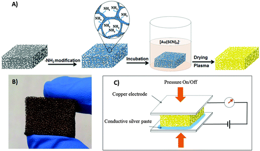
Fig. 1A depicts a scheme of the two-step assembly process for construction of the Au/PU piezoresistive sensor (detailed protocols are provided in the Experimental section). The starting material was a PU sponge – an inexpensive, highly deformable and flexible porous polymer which was previously employed as a platform for piezoresistive pressure sensors.41 The PU matrix was functionalized with amine (NH2) moieties by reaction with polyethileneimide (PEI; many other routes for amine functionalization of polymer networks are also available42). ζ-Potential measurements confirm coating of the PU sponge with amine moieties following functionalization (see Fig. S1 in ESI†).The amine-functionalized PU substrate was then immersed in an aqueous solution of gold thiocyanate, which produced a Au-coated PU sponge after drying and brief air-plasma treatment43 (Fig. 1B). A spontaneous reaction between water-soluble Au(SCN)4− and amine-displaying surfaces has been recently demonstrated as a versatile and effective technology for creation of conductive Au nanostructured films.44–46 This simple chemical process is based on the electrostatic attraction between the Au(SCN)4− complex and surface-displayed amine residues, and subsequent reduction of the Au3+ ions by the thiocyanate ligands, which ultimately produce conductive “gold nanoribbon” networks.44 Notably, this synthesis route employs readily-available and inexpensive reagents, and does not require co-addition of reducing agents or nanostructure templates. As depicted in Fig. 1C, the resultant Au/PU sponge comprised the core of the piezoresistive sensor, as its electrical resistance is modulated through compression/release of electrodes placed at either side (Fig. 1C).
Characterization of the Au/PU system
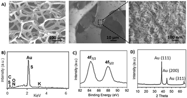
Table S1 (ESI†) provides the mechanical properties of the PU matrix before and after gold deposition. The details outlined in Table S1 (ESI†) indicate that after chemical oxidation, the rigid PU sponge became softer because of fiber fracture (i.e. decrease of Young's modulus). However, the deposition of gold coating did not significantly alter the mechanical properties of the sponge. The Au-coated PU sponge was characterized by several analytical techniques (Fig. 2). Fig. 2A depicts scanning electron microscopy (SEM) images of the material. The SEM image shows the fractured porous framework of the PU matrix; fracturing of the polymer scaffold was apparent following carboxylation (acid treatment) required for amine functionalization. While fracturing of the PU framework is not essential for achieving piezoresistive properties, it is believed to contribute to the flexibility and high sensitivity response to pressure changes.41 Indeed, we have found that fracturing improved the sensing properties of the Au/PU matrix. Similar enhanced pressure sensitivity was recently reported, accomplished through hydrothermal/mechanical PU fracturing. It should be noted, however, that the 90 second acid treatment reported here is simpler and significantly less time-consuming than the reported process.41The magnified area shown in the SEM image in Fig. 2A (right image) shows a dense coating of Au nanoribbons; the corresponding Energy-dispersive X-ray spectrum in Fig. 2B further confirms that gold deposition occurred within the porous framework of the PU sponge. The presence of metallic crystalline gold was verified by X-ray photoelectron spectroscopy (XPS, Fig. 2C) and X-ray diffraction (XRD, Fig. 2D) experiments. Specifically, the XPS spectrum in Fig. 2C indicates that the nanoribbon coating comprised of Au0, giving rise to peaks at 84.4 eV and 88.1 eV.
The XRD pattern in Fig. 2D corroborates the XPS result and further underscores the crystalline organization of the gold nanoribbons. Indeed, the XRD pattern in Fig. 2D reveals the distinctive reflections corresponding to crystal planes of metallic Au. Together, the spectroscopy data in Fig. 2 confirm the occurrence of crystallization/reduction of gold, resulting in deposition of crystalline metallic Au0 through a spontaneous reaction between the amine-functionalized PU sponge surface and Au(SCN)4−. Importantly, no reducing agents were co-added to the reaction mixture – in contrast to the significant majority of experimental schemes reported for controlled synthesis of Au nanostructures.47 This distinction reflects the contribution of the thiocyanate ligands as the electron-donating entities in the Au(SCN)4− system.4
The role of plasma treatment in the fabrication process of the new piezoresistive sensor is twofold. First, plasma treatment was designed to remove the organic residues (–SCN, –CN) in the gold film. The oxygen species created in the plasma (O2+, O2−, O3, O, O+, O−, ionized ozone, metastable excited oxygen) and free electrons react with organic contaminants to form H2O, CO, CO2, and lower molecular weight hydrocarbons. These compounds have relatively high vapour pressures and are evacuated from the chamber during processing. Second, the electrons produced in the plasma gas react with the deposited gold cations, reducing them to crystalline gold species. Powder X-ray diffraction and X-ray photoelectron spectroscopy data (Fig. S2, ESI†) confirm that plasma treatment effectively reduced the Au cations.
Pressure-dependent electrical properties of the Au/PU sponge of the Au/PU system
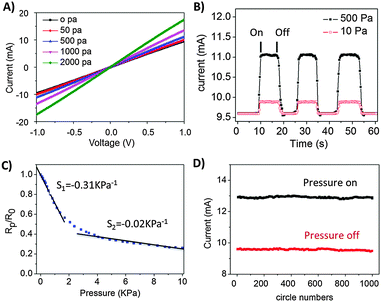
Fig. 3 highlights the piezoresistive properties of the newly assembled Au/PU sponges. Fig. 3A depicts the current–voltage (I–V) curves recorded upon placing the sponge between two flat copper electrodes and applying different pressures (according to the experimental scheme in Fig. 1C). The linear I–V curves and milliampere current range shown in Fig. 3A attest to the excellent conductivity attained in the Au/PU sponge system. The calculated conductivity of the Au/PU sponge was about 0.24 S m−1 (no applied pressure). Furthermore, Fig. 3A shows that the slopes of the I–V curves were dependent upon the pressures applied, reflecting the relationship between the sponge resistance and pressure exerted between the two planar electrodes. The pressure-dependent electrical conductivity shown in Fig. 3A is explained by the increased contact areas among the Au nanoribbon films attained upon compressing the sponge (e.g. contracting the internal pores), thereby enhancing electron transport and reducing the overall resistance of the Au/PU sponge.36,41 The opposite process (reduced internal contact area) occurs when less pressure is applied.The electrical current values of the Au/PU piezoresistive sponge recorded upon application of different pressures are outlined in Fig. 3B. Importantly, Fig. 3B demonstrates that the output signals generated upon on/off pressure applications are sharp, uniform, and reversible. Furthermore, the pressure threshold obtained (e.g. sensor sensitivity) is lower than 10 Pa, a sensitivity threshold that is on par or better than many reported pressure sensors (which, by comparison, are mostly more difficult to fabricate).36,48 To quantitatively assess the pressure sensitivity of the new Au/PU system we plotted Rp/R0 [in which Rp is the resistance at applied pressure p, and R0 is the resistance without applied pressure] vs. the applied pressure p (Fig. 3C). The two linear fits in Fig. 3C and calculated slopes (S1 and S2 indicated on the plot) reflect the distinct pressure regimes usually observed in chemically-assembled pressure sensors.28,41 Specifically, a steeper slope is apparent upon initial pressure applied – in which even slight changes in pressure significantly affect the contact area between the Au-coated polymer fibers and consequently alter the corresponding resistance. In the high pressure regime (above ∼2 kPa, Fig. 3C), modulation of the internal contact area within the sponge is less pronounced upon changing the pressure, giving rise to a lower slope.
The pressure sensitivities obtained in the Au/PU system and highlighted in Fig. 3C are similar or better than previously reported pressure sensors and attest to the excellent response parameters of the Au/PU system.36,48Fig. 3D underscores the stability of the Au/PU sponge as a pressure sensor. The graph in Fig. 3D shows the current values recorded upon application of a 1000 on/off pressure cycles; no significant drift is observed in the recorded current. The response time of the new piezoresistive sensor was lower than 10 ms (Fig. S4, ESI†), further supporting practical sensing applications.
Arterial pulse sensing by the Au/PU sponge
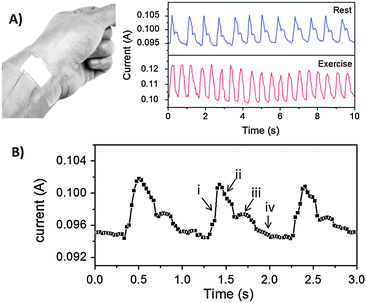
Fig. 4 presents an example of a practical use of the Au/PU sponge as a physiological sensing platform (other pressure sensing applications are presented in Fig. S3 in ESI†). Specifically, the graphs in Fig. 4 depict the current variations induced by blood pulses recorded upon placing the sponge upon the wrist artery (as shown in the photograph in the inset, Fig. 4A). The high fidelity and sensitive pulse measurements by the piezoresistive Au/PU sensor are apparent in the variation of current with time depicted in Fig. 4A. Furthermore, the pressure sensor clearly distinguishes between pulse profiles recorded at rest and following physical activity (Fig. 4A, right panel). The rapid response of the Au/PU sensor to pressure modulation enables high resolution monitoring of the arterial pulses and illuminate even small variations in blood pressures. (As shown in Fig. S4 in ESI,† the response time of this Au/PU sensor is less than 10 ms.) Specifically, Fig. 4B depicts high temporal resolution current plots of several pulses recorded at rest. Importantly, Fig. 4B demonstrates that the piezoresistive Au/PU sensor is capable of distinguishing fine features of the arterial line waveform, including the steep systolic uptake and gradual decline, the dicrotic notch, and diastolic runoff (indicated, respectively, by the Roman numerals in Fig. 4B).49Conclusions
In conclusion, we developed a new sensitive pressure sensor based on a simple, easy to produce construct comprising an amine-functionalized polyurethane sponge coated with a thin layer of Au nanoribbons. The Au/PU sponge exhibits excellent pressure sensing parameters, including stability and reproducibility, high sensitivity, and low response threshold. We demonstrate application of the new pressure sensor for monitoring arterial pulses. In particular, the fast response time and sensitivity made possible high resolution analysis of the pulse waveform features. The straightforward fabrication route using readily available and inexpensive chemical components, favourable physical properties and operation parameters of the Au/PU sponge system underscore the potential implementation of the new piezoresistive platform in varied pressure sensing applications.Acknowledgements
We are grateful to the Israel Science Foundation for financial support. We thank Dr Natalya Froumin and Dr Dimitry Mogiliansky for help with the XPS and XRD measurements, respectively.Notes and references
- V. Maheshwari and R. Saraf, Angew. Chem., Int. Ed., 2008, 47, 7808 CrossRef CAS PubMed.
- D.-H. Kim, N. Lu, R. Ma, Y.-S. Kim, R.-H. Kim, S. Wang, J. Wu, S. M. Won, H. Tao, A. Islam, K. J. Yu, T.-i. Kim, R. Chowdhury, M. Ying, L. Xu, M. Li, H.-J. Chung, H. Keum, M. McCormick, P. Liu, Y.-W. Zhang, F. G. Omenetto, Y. Huang, T. Coleman and J. A. Rogers, Science, 2011, 333, 838 CrossRef CAS PubMed.
- A. N. Sokolov, B. C. Tee, C. J. Bettinger, J. B.-H. Tok and Z. Bao, Acc. Chem. Res., 2011, 45, 361 CrossRef PubMed.
- M. L. Hammock, A. Chortos, B. C. K. Tee, J. B. H. Tok and Z. Bao, Adv. Mater., 2013, 25, 5997 CrossRef CAS PubMed.
- Z. L. Wang, ACS Nano, 2013, 7, 9533 CrossRef CAS PubMed.
- D. J. Cohen, D. Mitra, K. Peterson and M. M. Maharbiz, Nano Lett., 2012, 12, 1821 CrossRef CAS PubMed.
- J. J. Boland, Nat. Mater., 2010, 9, 790 CrossRef CAS PubMed.
- J. Livage, Nat. Mater., 2003, 2, 297 CrossRef CAS PubMed.
- K. Takei, T. Takahashi, J. C. Ho, H. Ko, A. G. Gillies, P. W. Leu, R. S. Fearing and A. Javey, Nat. Mater., 2010, 9, 821 CrossRef CAS PubMed.
- M. Madsen, K. Takei, R. Kapadia, H. Fang, H. Ko, T. Takahashi, A. C. Ford, M. H. Lee and A. Javey, Adv. Mater., 2011, 23, 3115 CrossRef CAS PubMed.
- N. T. Tien, S. Jeon, D. I. Kim, T. Q. Trung, M. Jang, B. U. Hwang, K. E. Byun, J. Bae, E. Lee and J. B. H. Tok, Adv. Mater., 2014, 26, 796 CrossRef PubMed.
- T. Someya, T. Sekitani, S. Iba, Y. Kato, H. Kawaguchi and T. Sakurai, Proc. Natl. Acad. Sci. U. S. A., 2004, 101, 9966 CrossRef CAS PubMed.
- D. J. Lipomi, M. Vosgueritchian, B. C. Tee, S. L. Hellstrom, J. A. Lee, C. H. Fox and Z. Bao, Nat. Nanotechnol., 2011, 6, 788 CrossRef CAS PubMed.
- G. Schwartz, B. C.-K. Tee, J. Mei, A. L. Appleton, D. H. Kim, H. Wang and Z. Bao, Nat. Commun., 2013, 4, 1859 CrossRef PubMed.
- J. Kim, T. N. Ng and W. S. Kim, Appl. Phys. Lett., 2012, 101, 103308 CrossRef PubMed.
- J. Zhou, P. Fei, Y. Gao, Y. Gu, J. Liu, G. Bao and Z. L. Wang, Nano Lett., 2008, 8, 2725 CrossRef CAS PubMed.
- S. Hung, B. Chou, C. Chang, C. Lo, K. Chen, Y.-L. Wang, S. Pearton, A. Dabiran, P. Chow and G. Chi, Appl. Phys. Lett., 2009, 94, 043903 CrossRef PubMed.
- Y. Hu, J. Zhou, P. H. Yeh, Z. Li, T. Y. Wei and Z. L. Wang, Adv. Mater., 2010, 22, 3327 CrossRef CAS PubMed.
- X. Wen, W. Wu, Y. Ding and Z. L. Wang, Adv. Mater., 2013, 25, 3371 CrossRef CAS PubMed.
- Z. L. Wang, Adv. Mater., 2012, 24, 280 CrossRef CAS PubMed.
- Z. L. Wang and W. Wu, Angew. Chem., Int. Ed., 2012, 51, 11700 CrossRef CAS PubMed.
- C. Pan, L. Dong, G. Zhu, S. Niu, R. Yu, Q. Yang, Y. Liu and Z. L. Wang, Nat. Photonics, 2013, 7, 752 CrossRef CAS PubMed.
- W. Wu, X. Wen and Z. L. Wang, Science, 2013, 340, 952 CrossRef CAS PubMed.
- L. Chen, G. Chen and L. Lu, Adv. Funct. Mater., 2007, 17, 898 CrossRef CAS PubMed.
- K. Lee, S. S. Lee, J. A. Lee, K.-C. Lee and S. Ji, Appl. Phys. Lett., 2010, 96, 013511 CrossRef PubMed.
- Y. Wang, R. Yang, Z. Shi, L. Zhang, D. Shi, E. Wang and G. Zhang, ACS Nano, 2011, 5, 3645 CrossRef CAS PubMed.
- M. K. Abyaneh and S. K. Kulkarni, J. Phys. D: Appl. Phys., 2008, 41, 135405 CrossRef.
- Q. Shao, Z. Niu, M. Hirtz, L. Jiang, Y. Liu, Z. Wang and X. Chen, Small, 2014, 10, 1466 CrossRef CAS PubMed.
- T. Sekitani, Y. Noguchi, K. Hata, T. Fukushima, T. Aida and T. Someya, Science, 2008, 321, 1468 CrossRef CAS PubMed.
- M. Park, J. Im, M. Shin, Y. Min, J. Park, H. Cho, S. Park, M.-B. Shim, S. Jeon and D.-Y. Chung, Nat. Nanotechnol., 2012, 7, 803 CrossRef CAS PubMed.
- L. Chen, S. Jin and T. Tiefel, Appl. Phys. Lett., 1993, 62, 2440 CrossRef CAS PubMed.
- B. Zhu, Z. Niu, H. Wang, W. R. Leow, H. Wang, Y. Li, L. Zheng, J. Wei, F. Huo and X. Chen, Small, 2014, 10, 3625 CrossRef CAS PubMed.
- B. Su, S. Gong, Z. Ma, L. W. Yap and W. Cheng, Small, 2014, 11, 1886 CrossRef PubMed.
- W. Chen, R. Rakhi, L. Hu, X. Xie, Y. Cui and H. Alshareef, Nano Lett., 2011, 11, 5165 CrossRef CAS PubMed.
- X. Xie, G. Yu, N. Liu, Z. Bao, C. S. Criddle and Y. Cui, Energy Environ. Sci., 2012, 5, 6862 CAS.
- J.-W. Han, B. Kim, J. Li and M. Meyyappan, Appl. Phys. Lett., 2013, 102, 051903 CrossRef PubMed.
- H. Hu, Z. Zhao, W. Wan, Y. Gogotsi and J. Qiu, ACS Appl. Mater. Interfaces, 2014, 6, 3242 CAS.
- S. Gong, W. Schwalb, Y. Wang, Y. Chen, Y. Tang, J. Si, B. Shirinzadeh and W. Cheng, Nat. Commun., 2014, 5, 3132 Search PubMed.
- S. Stassi, V. Cauda, G. Canavese, D. Manfredi and C. F. Pirri, Eur. J. Inorg. Chem., 2012, 2669 CrossRef CAS PubMed.
- S. Stassi, V. Cauda, G. Canavese and C. F. Pirri, Sensors, 2014, 14, 5296 CrossRef CAS PubMed.
- H. B. Yao, J. Ge, C. F. Wang, X. Wang, W. Hu, Z. J. Zheng, Y. Ni and S. H. Yu, Adv. Mater., 2013, 25, 6692 CrossRef CAS PubMed.
- N. Zammatteo, C. Girardeaux, D. Delforge, J.-J. Pireaux and J. Remacle, Anal. Biochem., 1996, 236, 85 CrossRef CAS PubMed.
- S. W. Lee, D. Liang, X. P. A. Gao and R. M. Sankaran, Adv. Funct. Mater., 2011, 21, 2155 CrossRef CAS PubMed.
- A. Morag, N. Froumin, D. Mogiliansky, V. Ezersky, E. Beilis, S. Richter and R. Jelinek, Adv. Funct. Mater., 2013, 23, 5663 CrossRef CAS PubMed.
- T. P. Vinod and R. Jelinek, ACS Appl. Mater. Interfaces, 2014, 6, 3341 CAS.
- A. Trachtenberg, T. P. Vinod and R. Jelinek, Polymer, 2014, 55, 5095 CrossRef CAS PubMed.
- A. Morag, L. Philosof-Mazor, R. Volinsky, E. Mentovich, S. Richter and R. Jelinek, Adv. Mater., 2011, 23, 4327 CrossRef CAS PubMed.
- H. B. Yao, G. Huang, C. H. Cui, X. H. Wang and S. H. Yu, Adv. Mater., 2011, 23, 3643 CrossRef CAS PubMed.
- B. H. McGhee and E. J. Bridges, Crit. Care Nurse, 2002, 22, 60 Search PubMed.
Footnote |
| † Electronic supplementary information (ESI) available. See DOI: 10.1039/c5tc01604e |
| This journal is © The Royal Society of Chemistry 2015 |


