
 Open Access Article
 This Open Access Article is licensed under a Creative Commons Attribution-Non Commercial 3.0 Unported Licence
Near infrared-emitting tris-bidentate Os(II) phosphors: control of excited state characteristics and fabrication of OLEDs†
Jia-Ling
Liao
a,
Yun
Chi
*a,
Chia-Chi
Yeh
b,
Hao-Che
Kao
b,
Chih-Hao
Chang
*b,
Mark A.
Fox
 c,
Paul J.
Low
*d and
Gene-Hsiang
Lee
e
c,
Paul J.
Low
*d and
Gene-Hsiang
Lee
e
aDepartment of Chemistry and Low Carbon Energy Research Center, National Tsing Hua University, Hsinchu 30013, Taiwan. E-mail: ychi@mx.nthu.edu.tw
bDepartment of Photonics Engineering, Yuan Ze University, Chungli 32003, Taiwan. E-mail: chc@saturn.yzu.edu.tw
cDepartment of Chemistry, Durham University, South Rd, Durham, DH1 3LE, UK
dSchool of Chemistry and Biochemistry, University of Western Australia, 35 Stirling Highway, Crawley, 6009, Western Australia, Australia. E-mail: paul.low@uwa.edu.au
eInstrumentation Center, National Taiwan University, Taipei 10617, Taiwan
First published on 14th April 2015
Abstract
A series of four Os(II) complexes bearing (i) chromophoric diimine ligands (N^N), such as 2,2′-bipyridine (bpy) and substituted 1,10-phenanthrolines, (ii) dianionic bipz chelate ligands derived from 5,5′-di(trifluoromethyl)-2H,2′H-3,3′-bipyrazole (bipzH2), and (iii) bis(phospholano)benzene (pp2b) as the third ancillary ligand completing the coordination sphere were synthesized. X-ray diffraction studies confirm the heteroleptic tris-bidentate coordination mode. These Os(II) complexes [Os(N^N)(bipz)(pp2b)], N^N = bpy (3), phenanthroline (4), 3,4,7,8-tetramethyl-1,10-phenanthroline (5) and 4,7-diphenyl-1,10-phenanthroline (6), display near infrared (NIR) emission between 717 nm and 779 nm in the solid state at RT. On the basis of hybrid-DFT and TD-DFT calculations, the emissions are assigned to metal-to-ligand charge transfer transitions (3MLCT) admixed with small ligand-to-ligand charge transfer (3LLCT) contributions. Successful fabrication of organic light emitting diodes (OLEDs) using Os(II) complex 5 as the dopant and either tris(8-hydroxyquinoline) aluminum (Alq3) or 3,3′,5,5′-tetra[(m-pyridyl)-phen-3-yl]-biphenyl (BP4mPy) as the host is reported. These OLEDs were measured with emission maxima at 690 nm and extending into the NIR, with peak power efficiencies of up to 0.13 lm W−1 and external quantum efficiencies of up to 2.27%.
Introduction
Phosphorescent metal complexes have been extensively investigated during the past two decades due to the profound interest in basic photophysics1–9 and applications in organic light emitting diodes (OLEDs) suited for the fabrication of flat panel displays10–13 and luminaires.14–19 As a consequence of the need for these applications, many studies have focused on achieving bright visible emission, with colors spanning from blue and green to red. Another class of compounds being of great interest is near infrared (NIR) emitting materials; i.e. those with emission peak maximum exceeding 700 nm.20–22 NIR-emitting materials can find application in biological imaging, sensing and optical tele-communication platforms. Among the various systems explored to date, Pt(II) complexes constitute a class of molecules that have shown the most efficient NIR emission,23–27 either through the use of chelating ligands with extended peripheral π-conjugation or by engineering strong π–π stacking interactions among molecules in the solid state for excimer formation. For example, electroluminescence with peak maximum at 772 nm and an external quantum efficiency (EQE) of 5.0% was documented for Pt(II) tetraphenyltetrabenzoporphyrin,28 while the maximum EQE was further improved to 9.2% through the introduction of the 3,5-di-tert-butylphenyl substituted tetrabenzoporphyrin to control intermolecular interactions and suppress triplet–triplet annihilation.29However, promising results in the area of NIR-emitting materials are not restricted to Pt(II) complexes, and both Ru(II) complexes with π-bonded (η4-) orthoquinone ligands,30 Ir(III) complexes bearing cyclometalated heteroaromatics,31–34 or with azabenz-annulated perylene bisimide35 stand as illustrative examples of other metal-containing NIR-emitting materials. Parallel to this endeavor, we have developed Os(II) phosphors bearing isoquinolinyl azolate chelate ligands, which lower the emission energy gaps and bring emission into the NIR region.36,37 The two Os(II) complexes [Os(bpy)(dttz)(CO)2] (1a) and [Os(bpy)(dttz)(PPhMe2)2] (2) bearing both the neutral 2,2′-bipyridine (bpy) and dianionic 3,3′-bi-1,2,4-triazolate (dttz2−) chelating ligands also serve to demonstrate important molecular design features (Chart 1). In complex 2 due to the increase in electron density at the Os(II) metal centre brought about by the phosphine co-ligands, we can take advantage of the combined metal-to-ligand charge transfer (MLCT) and the ligand-to-ligand charge transfer (LLCT) transitions to achieve NIR-emitting characteristics.38
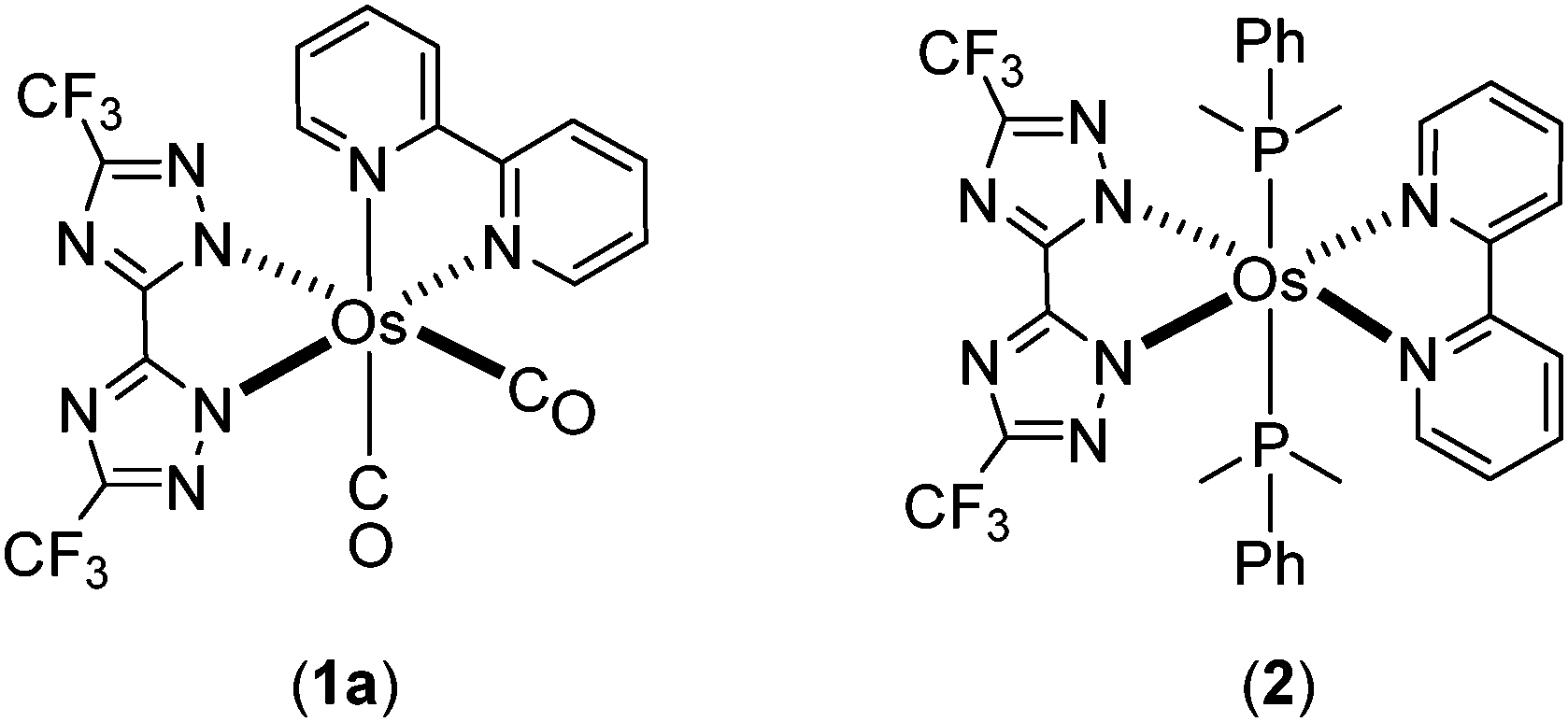 | ||
| Chart 1 Reported Os(II) complexes 1a and 2. | ||
To further explore the methodology to tune emission into the NIR region, we have designed heteroleptic tris-chelating Os(II) complexes containing (i) bpy or 1,10-phenanthroline as the chelate with lower lying π*-orbitals, (ii) 5,5′-di(trifluoromethyl)-3,3′-bipyrazolate (bipz2−) as a dianionic and strongly electron donating chelate, and (iii) 1,2-bis(phospholano)benzene (pp2b) as the third bidentate chelate to impose the formation of all cis-coordination geometry. The photophysical and structural characterization of the resulting NIR-emitting Os(II) complexes and the device performance of the NIR-emitting OLEDs formed from these compounds are described here.
Results and discussion
Syntheses and characterization
It has been reported that the cluster complex Os3(CO)12 reacts with functional pyrazoles (or triazoles) to form isolable intermediate derivatives via CO elimination.39–43 Subsequent sequential addition of Me3NO and phosphines at elevated temperature led to the formation of mononuclear Os(II) complexes with diverse structures and distinctive photophysical properties. Such synthetic procedures were employed to prepare the aforementioned complexes cis-[Os(bpy)(dttz)(CO)2] (1a) and phosphine substituted trans-[Os(bpy)(dttz)(PMe2Ph)2] (2).38Here, this synthetic procedure was extended through reactions of Os3(CO)12 with the distinctive dipyrazole pro-ligand 5,5′-di(trifluoromethyl)-2H,2′H-3,3′-bipyrazole (bipzH2) and a range of diimine chelates (N^N = bpy, phenanthroline (phen), 3,4,7,8-tetramethyl-1,10-phenanthroline (Me4phen), and 4,7-diphenyl-1,10-phenanthroline (Ph2phen)) to give cis-[Os(bipz)(N^N)(CO)2] (isolated by way of example for N^N = bpy, 1b). Further reaction with anhydrous Me3NO and 1,2-bis(phospholano)benzene (pp2b) gave the tris-heteroleptic complexes [Os(bipz)(N^N)(pp2b)] (3–6) (Chart 2).
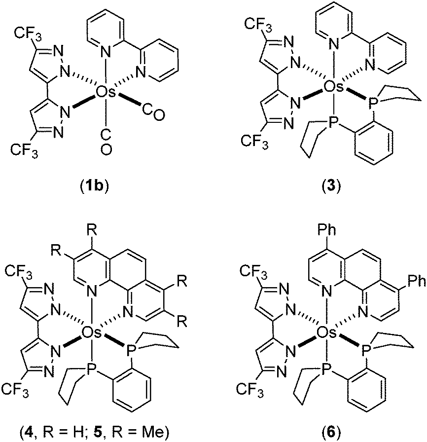 | ||
| Chart 2 Os(II) complexes 1b and 3–6 investigated in this study. | ||
However, the synthetic yields for 3–6 (21–35%) are notably lower than that obtained for the trans-complex 2 (∼50%). Varying the cis-diphosphine, such as to 1,2-diphenylphosphinobenzene, failed to afford any isolable product, which is in contrast to previous reactions,44 showing the delicate balance of structural and electronic effects imposed by the phosphines.
All of the new Os(II) metal complexes, i.e.1b and 3–6, were purified by silica gel column chromatography and recrystallization, and then fully characterized by mass spectrometry, IR and NMR spectroscopies and elemental analyses. Multinuclear NMR spectra clearly established the heteroleptic nature of the complexes; for example, complex 3 showed two distinctive 1H NMR singlet signals at δ 6.54 and 6.39 and two 19F NMR signals at δ −59.62 and −59.65 assigned to the bipz chelate, characteristic multiplets from the bpy ligand, and two well separated 31P NMR signals at δ 39.88 and 33.80 due to the coordinated pp2b ligand. Therefore, these data clearly confirmed the presence of the three distinct chelating ligands coordinated to the Os(II) atom. Moreover, the IR ν(CO) bands of the dicarbonyl complex 1b were found at 1978 and 2040 cm−1, which are located at lower wavenumbers than those of 1a (i.e. 1994 and 2058 cm−1) which contains the bis(triazolate) ligand, dttz.38 This observation is in agreement with the greater electron donating character of bipz, and the increased back π-bonding which serves to reduce the CO stretching frequencies.
The structures of 1b and 3 were determined by single crystal X-ray diffraction, for which a perspective view of each molecule, selected bond distances and angles are shown in Fig. 1 and 2. Both Os(II) complexes adopt a distorted octahedral geometry at the metal centre, with the bpy and bipz chelates being located cis to each other, leaving two remaining cis-coordination sites that are occupied by two CO ligands (1c) or the pp2b chelate (3). In complex 1b, the trans-influence of the CO ligands increases the trans-Os–N distances (i.e. Os–N(2) = 2.102(4) and Os–N(6) = 2.121(4) Å) versus those at the cis-dispositions, cf. Os–N(3) = 2.057(4) and Os–N(5) = 2.080(4) Å.39 For the pp2b complex 3, since both the trans-Os–N distances, i.e. Os–N(3) = 2.113(6) and Os–N(6) = 2.123(5) Å, are comparable to the trans-Os–N distances observed in 1c, the trans-influence of the pp2b chelate should be at the same magnitude as that imposed by dual CO ligands, despite the large distinction in their intrinsic characters, i.e. σ-donor vs. π-acceptor.45 Moreover, the bipz chelate in 3 adopts a subtly bent conformation, which is in contrast to the near-planar arrangement of this ligand in 1b. Since pp2b is more sterically bulky than the CO ligands, the associated crystal-packing effect, in part, likely influences this conformational distortion in the crystal lattice.46
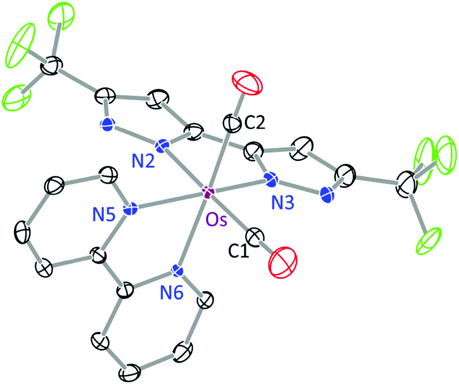 | ||
| Fig. 1 ORTEP diagram of 1b with thermal ellipsoids shown at the 30% probability level; selected bond distances: Os–N(2) = 2.102(4), Os–N(3) = 2.057(4), Os–N(5) = 2.080(4), Os–N(6) = 2.121(4), Os–C(1) = 1.892(6) and Os–C(2) = 1.895(6) Å; bond angles: ∠C(1)–Os–C(2) = 87.8(2), N(5)–Os–N(6) = 77.94(16) and N(2)–Os–N(3) = 76.85(17)°. | ||
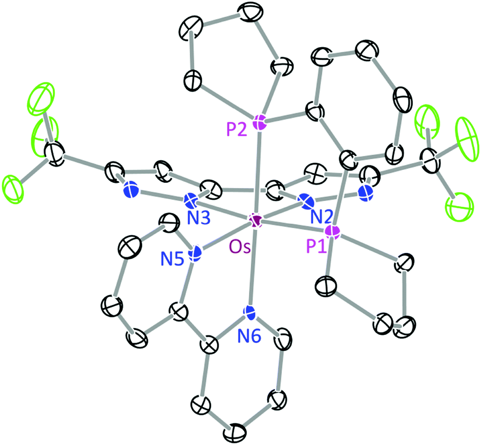 | ||
| Fig. 2 ORTEP diagram of 3 with thermal ellipsoids shown at the 30% probability level; selected bond distances: Os–N(2) = 2.088(5), Os–N(3) = 2.113(6), Os–N(5) = 2.072(6), Os–N(6) = 2.123(5), Os–P(1) = 2.2650(17) and Os–P(2) = 2.2618(17) Å; bond angles: ∠P(1)–Os–P(2) = 85.36(6), N(5)–Os–N(6) = 77.1(2) and N(2)–Os–N(3) = 76.2(2)°. | ||
Photophysical data
Complex 1b is non-emissive in both solution and solid states, so the discussion of photophysical properties is focused only on the phosphine substituted Os(II) complexes 3–6. For these complexes, UV-Vis absorption spectra were recorded in CH2Cl2 and the numerical data are presented in Table 1. As shown in Fig. 3, the absorption spectra exhibit strong absorption bands below 320 nm (ε > 3 × 10⁴ M−1cm−1) assigned to 1π–π* transitions localized on the diimine ligands. The next lower energy absorption in the region 400–500 nm (ε = 4–10 × 103 M−1cm−1) is attributed to the spin-allowed 1MLCT transitions from the Os(II) metal ion to the diimine. The intensities of these 1MLCT bands show strong correlation with the nature of the diimine ligands; i.e. complexes 3 and 6 give the weakest and greatest intensity transitions which may be due in part to the degree of π-conjugation in the diimine acceptor. Moreover, there is a very broad absorption envelope that extends beyond 600 nm (ε = 1.2–2.1 × 10³ M−1 cm−1), which can be assigned to the heavy-metal atom enhanced 3MLCT absorption, probably mixed with a contribution from the ligand-to-ligand charge transfer (3LLCT) transitions from the occupied orbital of bipz to the empty π*-orbital of the diimine chelate.| Abs. λmax (nm) [ε (103 M−1 cm−1)]a | PL λmaxb (nm) | Φ (%) | τ obs (ns) | k r (105 s−1) | k nr (107 s−1) | |
|---|---|---|---|---|---|---|
| a UV-Vis spectra were recorded in 10−5 M of CH2Cl2 solution. b Photoluminescence spectra and quantum yields were measured as neat powder. | ||||||
| 3 | 295 [27.9], 338 [5.4], 471 [4.1], 610 [1.2] | 772 | 0.5 | 26.4 | 1.89 | 3.76 |
| 4 | 268 [43.0], 406 [6.1], 586 [1.2] | 739 | 3.1 | 197 | 1.52 | 0.49 |
| 5 | 273 [57.4], 442 [6.9], 545 [1.7] | 717 | 8.8 | 431 | 2.04 | 0.21 |
| 6 | 279 [64.2], 476 [10.3], 599 [2.1] | 779 | 4.5 | 115 | 3.91 | 0.83 |
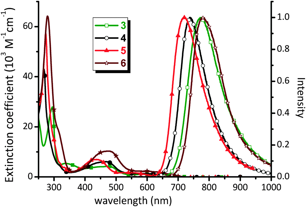 | ||
| Fig. 3 UV-Vis absorption spectra in CH2Cl2 and solid state emission spectra at RT of Os(II) complexes 3–6. | ||
The Os(II) complexes 3–6 failed to show any notable emission in solution at RT, but were significantly emissive in the solid state, a result of the rigid media as well as the forfeit of solvent collisions.47,48 The solid state emission spectra and associated peak maxima (Fig. 3) are sensitive to the nature of the diimine N^N chelate, supporting the assignment of the 3MLCT transition. For example, replacing the bpy chelate in 3 with the phen chelate in 4 leads to a blue shift of emission from 772 nm to 739 nm, which is due to the more destabilized π*-orbital of phen versus bpy.49–52 In a similar fashion, upon introduction of four methyl substituents (5) or two phenyl groups (6) into the phenanthroline ligand, the corresponding emission maxima are blue shifted relative to the parent complex 4 to 717 nm and red shifted to 779 nm, respectively. These variations are attributed to the electron donating and extended π-conjugation of the methyl and phenyl substituents respectively.
Complexes 3–6 showed emission quantum yields Φ = 0.5–8.8%, and relatively short luminescence lifetimes at RT (τobs = 26.4–431 ns) for phosphorescence processes. The radiative (kr) and nonradiative decay (knr) rates were calculated from the Φ and τ data. The low Φ value of 3 is principally caused by the less rigid molecular framework of the bpy ligand, which then increases knrversus other Os(II) complexes with more structurally rigid phenanthroline-based chelates.53 Within the series of phenanthroline complexes 4–6, complex 5 showed higher Φ and longer τobs values versus those of parent 4, which is best explained by the energy gap law,54,55i.e. knr values tend to increase as the emission energy decreases. In the case of complex 6 with the extended Ph2phen chelate, the Φ value of 4.5% is higher than 3.1% of 4, whilst τobs (115 ns) is comparable to that of parent complex 4 (197 ns). The derived kr and knr values for 6 are calculated to be 3.91 × 10⁵ and 0.83 × 10⁷ s−1, respectively. This could be due to the fact that, upon photoexcitation, the peripheral Ph substituents would become coplanar with the phenanthroline backbone, resulting in more extended electron delocalization in the excited state.56,57 Therefore, the better electron delocalization produces a smaller variation in the C–C bond lengths upon formation of the excited state as compared to the ground state and, ultimately, giving the larger radiative quantum yield relative to other molecules in this class.58
Electrochemistry
The electrochemical properties of 3–6 were examined using cyclic voltammetry (Table 2). The obtained data support the delineation that oxidation is localized on the Os(II) metal center, and that reduction occurs mainly on the diimine ligand.59 In the present system, all Os(II) complexes 3–6 showed a reversible oxidation potential in the narrow range of 0.00–0.07 V (vs. the ferrocenium/ferrocene couple at 0.0 V), whilst the reduction potential was recorded between −2.04 and −2.30 V (cf.Table 2 and Fig. S1 of the ESI†). The trends in reduction potentials followed the trends anticipated on the basis of the electron donating or withdrawing characteristics of the diimine ligands. Thus, changing from bpy to phen (i.e. from 3 to 4) and addition of four methyl groups to phen (i.e. from 4 to 5) result in the destabilization of the empty π*-orbital of the diimine chelate, and a consequent shift in the reduction potential to more negative values. For 5, the small decrease in oxidation potential versus4 is also coupled with the increase in electron density at the metal center exerted by four methyl groups on phen. The possibility to create a more extended π* system in the Ph2phen complex 6 gives the least negative reduction potential when compared with the parent compound 4.| Ox. E1/2a (V) [ΔEp (mV)] | Red. E1/2b (V) [ΔEp (mV)] | HOMOc (eV) | LUMOc (eV) | ||
|---|---|---|---|---|---|
| a Measured in 0.1 M TBAPF6/CH2Cl2vs. FcH+/FcH with the Pt working electrode. b Measured in 0.1 M TBAPF6/THF vs. FcH+/FcH with the Au working electrode. c B3LYP/LANL2DZ:6-31G** data. | |||||
| 3 | 0.07 [89] | −2.14 [124] | 3′ | −5.00 | −2.16 |
| 4 | 0.07 [99] | −2.22 [83] | 4′ | −5.00 | −2.13 |
| 5 | 0.00 [88] | −2.30 [73] | 5′ | −5.03 | −1.91 |
| 6 | 0.07 [72] | −2.04 [73] | 6′ | −4.98 | −2.18 |
DFT calculations
In order to gain in-depth insight into the above experimentally observed properties, we turned to calculations based on density functional theory (DFT) and time-dependent density functional theory (TD-DFT) (B3LYP/LANL2DZ basis set for Os, 6-31G** and all other atoms, as well as a conductor-like polarization continuum CPCM solvent model in CH2Cl2). The model structures are denoted 3′, 4′, 5′ and 6′ to distinguish them from the physical data of the as-synthesized complexes. The results from the geometry optimisation are summarised in Table 3, together with the crystallographically determined data from 3 for comparison. In the case of 3 and 3′, the majority of differences in bond lengths are within 0.03 Å, whilst the greatest difference is around 0.06 Å, associated with the Os–P(2) bond.| 3 | 3′ | 4′ | 5′ | 6′ | |
|---|---|---|---|---|---|
| Os–N(2) (in Å) | 2.088(5) | 2.1101 | 2.1077 | 2.0898 | 2.1098 |
| Os–N(3) | 2.113(6) | 2.1346 | 2.1349 | 2.1041 | 2.1353 |
| Os–N(5) | 2.072(6) | 2.1094 | 2.1207 | 2.0909 | 2.1192 |
| Os–N(6) | 2.123(5) | 2.1276 | 2.1387 | 2.1149 | 2.1308 |
| Os–P(1) | 2.2650(17) | 2.3334 | 2.3312 | 2.3068 | 2.3337 |
| Os–P(2) | 2.2618(17) | 2.3204 | 2.3174 | 2.3013 | 2.3185 |
| P(1)–Os–P(2) (in °) | 85.36(6) | 84.48 | 84.63 | 85.38 | 84.49 |
| N(2)–Os–N(3) | 76.2(2) | 75.95 | 76.05 | 75.92 | 75.94 |
| N(5)–Os–N(6) | 77.1(2) | 76.92 | 77.71 | 77.96 | 77.26 |
Plots of the HOMO and the LUMO of 3′, 4′, 5′ and 6′ are given in Fig. 4 and the ESI.† In each case, the HOMO is of mixed Os(d)–bipz(π) characteristics, (Os/bipz: 49/44 (3′); 48/45 (4′); 57/32 (5′); 49/44 (6′)) whilst the LUMO is strongly localized on the diimine ligand. The HOMO energies vary little across the series (Table 2) whilst the LUMO energies naturally follow the electronic characteristics of the diamine, giving good correlation with the redox potentials.
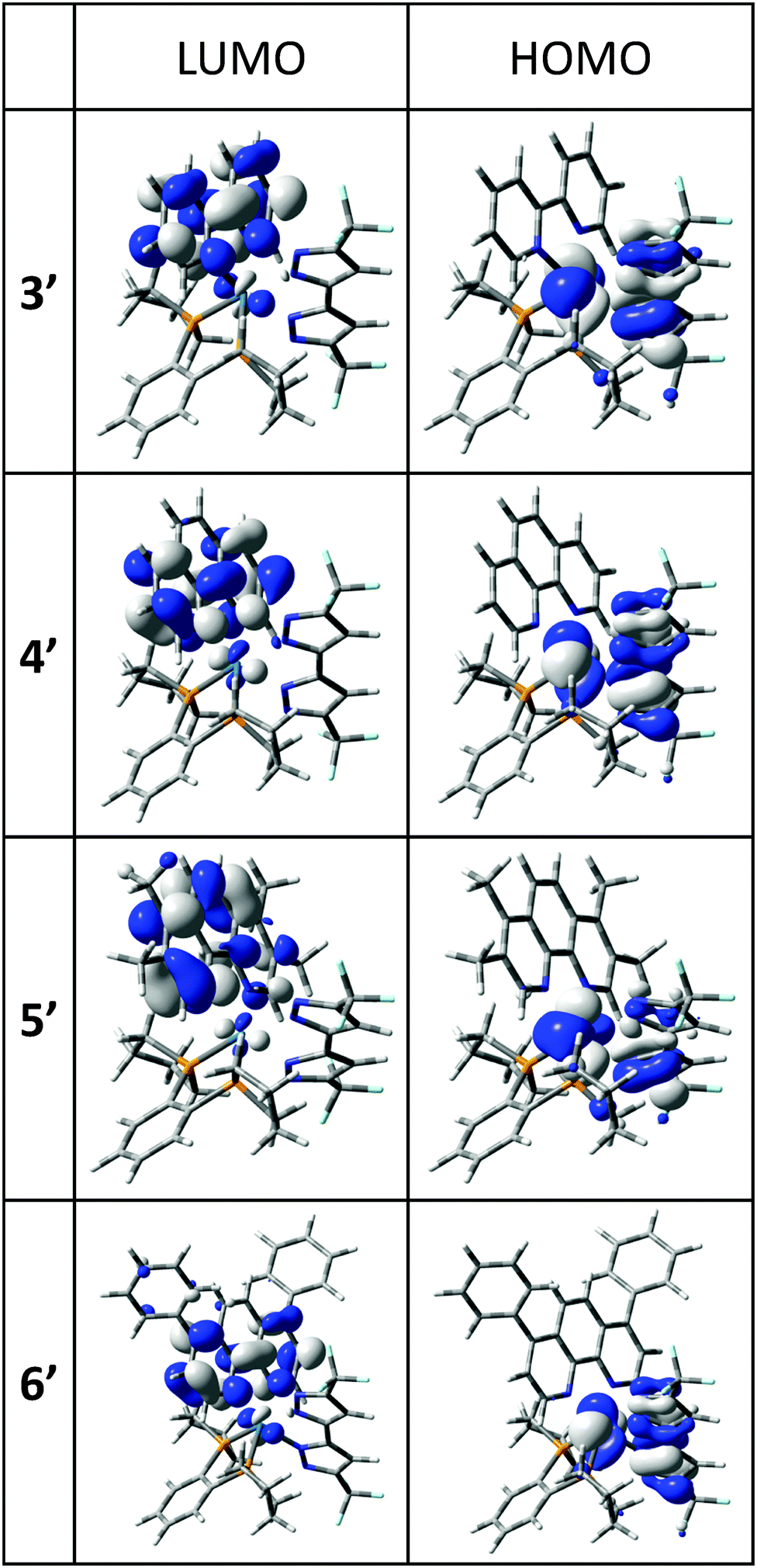 | ||
| Fig. 4 Frontier molecular orbitals in the lowest-energy optical transitions for Os(II) complexes 3′–6′; all contours are plotted at ±0.04 (e bohr−3)1/2. | ||
To provide a more detailed interpretation of the photophysical properties of 3–6, time-dependent density functional theory (TD-DFT) calculations were also carried out. The results are summarized in Table 4, which lists the energy and orbital analyses of the lowest energy singlet and triplet transitions, together with the relevant data from the absorption and emission spectra. The agreement between the calculated S0 → S1 transition energies is remarkably good, and although the S0 → T1 transition is strictly forbidden and the calculations do not allow for spin–orbit coupling, the calculated transition energies (albeit with zero oscillator strength) follow the trend in emission maxima (Table 4). The S0 → T1 transition energies may also account in part for the low energy tails observed in the absorption spectra (Fig. 3). The simulated absorption spectra of the Os(II) complexes 3–6 are given in the ESI.†
| Calc. λmax | Calc. λmax | Obs. λmax (abs) | Obs. λmax (em) | |
|---|---|---|---|---|
| S0 → S1 | S0 → T1 | |||
| 3′ | 607 | 644 | 610 | 772 |
| HOMO → LUMO (95%) | HOMO → LUMO (76%) | |||
| 4′ | 598 | 633 | 586 | 739 |
| HOMO → LUMO (95%) | HOMO → LUMO (70%) | |||
| 5′ | 533 | 596 | 545 | 717 |
| HOMO → LUMO (58%) | HOMO-1 → LUMO (52%) | |||
| HOMO → LUMO+1 (33%) | HOMO-2 → LUMO (26%) | |||
| 6′ | 608 | 651 | 599 | 779 |
| HOMO → LUMO (93%) | HOMO → LUMO (63%) |
The S0 → S1 and S0 → T1 transitions are assigned to HOMO → LUMO charge transfer processes of mixed MLCT/LLCT characteristics for each of 3′, 4′ and 6′. In the case of 5 which bears the Me4-phen ligand, the S0 → S1 transition also has appreciable HOMO → LUMO+1 characteristics (also MLCT/LLCT between the Os/bipz donor and the diimine) whilst the S0 → T1 transition is of mixed HOMO−1 → LUMO/HOMO−2 → LUMO characteristics (again, largely MLCT/LLCT in nature).
OLED device fabrication
For OLED device fabrication, complex 5 was selected as the dopant due to both the higher volatility and quantum yield compared with the other members of the series. In this study, tris(8-hydroxyquinoline)aluminum (Alq3) and 3,3′,5,5′-tetra[(m-pyridyl)-phen-3-yl]-biphenyl (BP4mPy) were used both as the host and the electron transport layer (ETL). The electron mobilities of Alq3 and BP4mPy are found to be 10−5 and 10−4 cm2 V−1 s−1, respectively.60–63 Moreover, 4,4′-bis[N-(1-naphthyl)-N-phenyl-amino] biphenyl (NPB) which possesses an adequate hole transport mobility (∼10−4 cm2 V−1 s−1) and a triplet energy gap (ET = 2.29 eV) was selected as the hole transport layer (HTL) in tuning the carrier balance.64–66 The devices A1 and B1 consist of the architecture: ITO/NPB (40 nm)/Host (Alq3 or BP4mPy) doped with x wt% 5 (30 nm)/ETL (Alq3 or BP4mPy) (40 nm)/LiF (0.5 nm)/Al (150 nm). In general, the concentrations of all RGB dopants in phosphorescent OLEDs range from 6 to 10 wt%. However, NIR OLEDs usually require higher concentrations to achieve the desired red-shifted EL spectrum; therefore, 8 wt% and 16 wt% concentrations were used here. The EL spectrum from the device with 16 wt% of dopant was slightly red-shifted compared to the EL spectrum from the device with 8 wt% of dopant. However, the device adopting 8 wt% doping concentration achieved a much higher efficiency value. Consequently, the doping concentration of 8 wt% was used in this study. Furthermore, based on our experiences, the device efficiency can be improved by using a second dopant with an intermediate energy level to provide a favorable stepwise energy transfer. The Os(II) complex [Os(fptz)2(PPh2Me)2] (7) was selected for this purpose as it exhibited a considerable spectral overlap with that of 5, as well as the optimal energy levels.40,67–69 This isoenergetic relationship allows efficient energy transfer from 7 to 5, and the emission remained unaltered due to the low concentration of 7.38,64 Therefore, the doped devices A2 and B2 were represented by the architecture: ITO/ NPB (40 nm)/Host (Alq3 or BP4mPy) doped with 8 wt% 5 and 0.1 wt% 7 (30 nm)/ETL (Alq3 or BP4mPy) (40 nm)/LiF (0.5 nm)/Al (150 nm). The materials employed in OLEDs along with complex 5 and an estimated energy-level diagram for the devices are depicted in Fig. 5.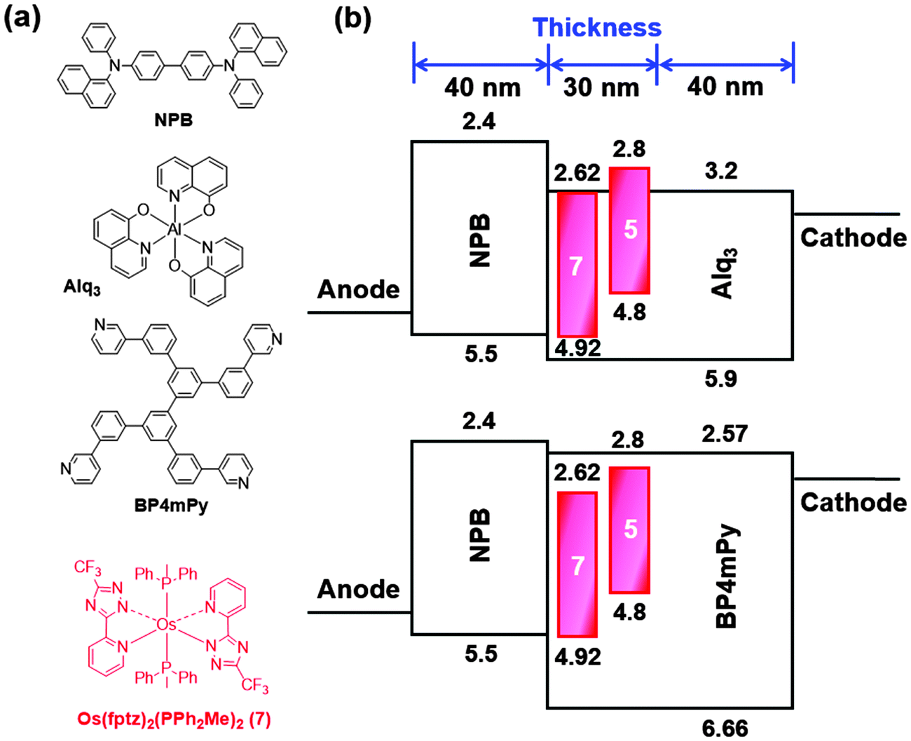 | ||
| Fig. 5 (a) Compounds used in OLEDs along with complex 5; (b) architecture of NIR OLEDs with the tested hosts, dopants and electron transport layers. | ||
The characteristics of the resulting devices are shown in Fig. 6, while the numerical data are listed in Table 5. As can be seen, all devices show nearly identical spectral profiles, for which the EL peak maxima (690 nm) show a broadened full width at half maximum (FWHM) of approx. 130 nm (or 2680 cm−1) and are also slightly blue-shifted with respect to photoluminescence (PL) recorded as neat powder (717 nm). It appears to us that the blue-shifting in EL spectra may be due to the effect of media, for which the co-deposition in host material may somewhat destabilize the 3MLCT excited states. Furthermore, the lack of Alq3 or BP4mPy emission implies that complete energy transfers take place from the hosts to the NIR dopant 5. Hence, the carrier recombination zone was confined within the emitting layer and the exciton diffusion to the adjacent carrier transport layers is avoided in the devices.
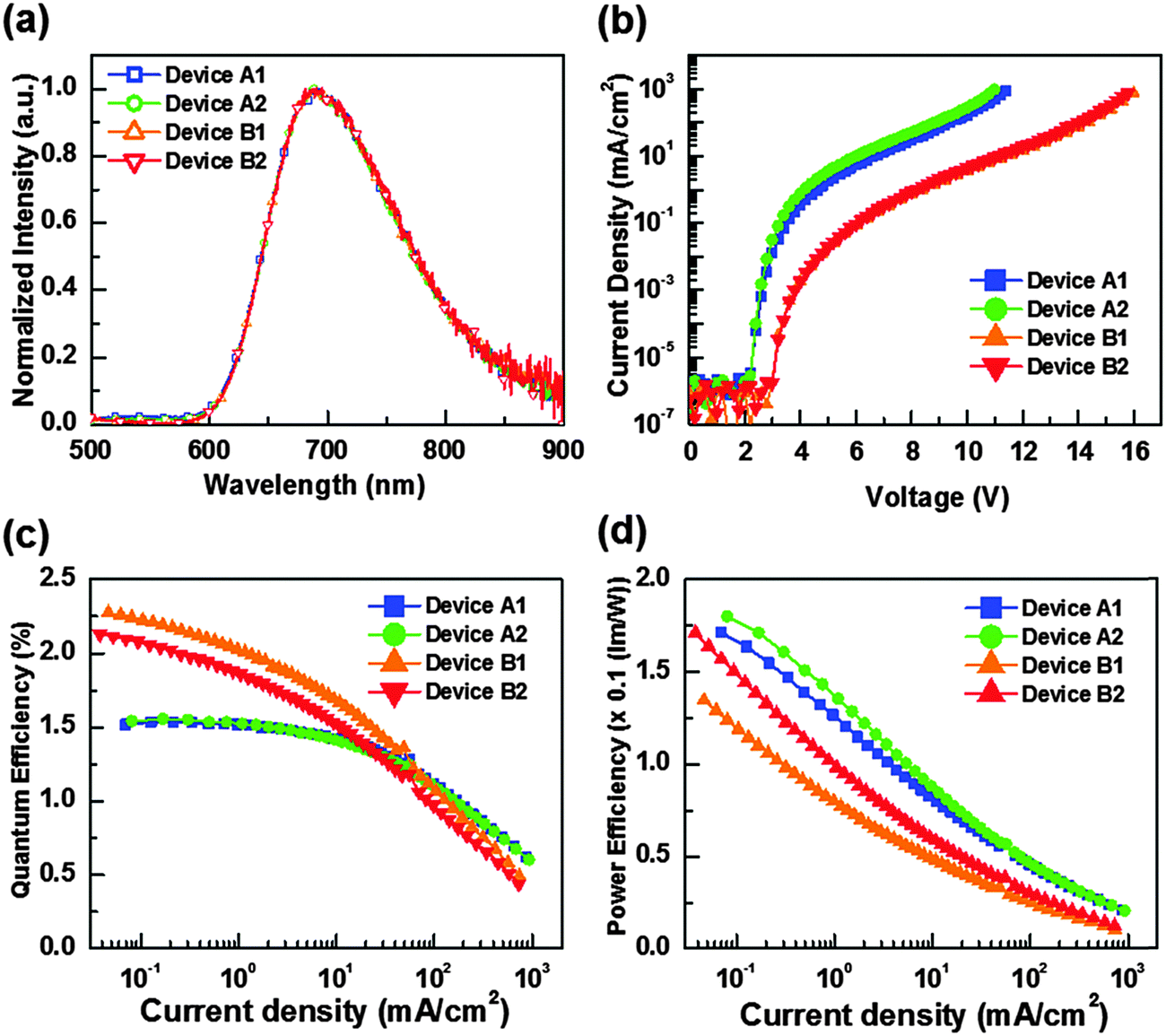 | ||
| Fig. 6 (a) EL spectra of tested OLEDs; (b) current density–voltage (J–V) plots; (c) external quantum efficiency vs. current density; (d) power efficiency vs. current density for devices A1, A2, B1 and B2. | ||
| Device | A1 | A2 | B1 | B2 | |
|---|---|---|---|---|---|
| Host & ETL | Alq3 | BP4mPy | |||
| Dopant | 5 | 5 + Os | 5 | 5 + Os | |
| External quantum efficiency (%) | Max. | 1.54 | 1.56 | 2.27 | 2.13 |
| 10 mA cm−2 | 1.42 | 1.41 | 1.68 | 1.53 | |
| Power efficiency (lm W−1) | Max. | 0.17 | 0.18 | 0.13 | 0.17 |
| 10 mA cm−2 | 0.08 | 0.09 | 0.05 | 0.06 | |
| Turn on voltage (V) | 2.2 | 2.2 | 3.0 | 3.0 | |
| J 1/2 (mA cm−2) | 473.2 | 441.9 | 82.3 | 69.5 | |
| CIE 1931 coordinates | (0.66, 0.34) | (0.67, 0.33) | (0.69, 0.31) | (0.69, 0.31) | |
| Light output (mW cm−2) [@V] | 53.9 [11.4 V] | 52.8 [11.0 V] | 48.9 [16.0 V] | 45.9 [15.8 V] | |
Moreover, the respective turn-on voltages (defined as a sharp rise in current density) for devices A1, A2, B1, and B2 are found to be 2.2 V, 2.2 V, 3.0 V and 3.0 V, respectively. Obviously, the higher band gap of BP4mPy produced higher operation voltages and lower current densities for devices B1 and B2 versus devices A1 and A2 that were fabricated using Alq3. As shown in Fig. 6(c) and (d), devices A1 and A2 showed poor external quantum efficiencies (EQE) at lower current densities, which might be attributed to the quenching induced by the charge carrier–exciton interaction.70 Peak EQEs of A1 and A2 were recorded to be 1.54% (0.17 lm W−1) and 1.56% (0.18 lm W−1), respectively. In contrast, the peak EQEs of B1 and B2 were higher, e.g. 2.27% (0.13 lm W−1) and 2.13% (0.17 lm W−1), respectively. This approx. 47% increase in EQEs demonstrated the effectiveness of BP4mPy in achieving the balanced carrier transport. On the other hand, both the co-doped devices A2 and B2 showed improved carrier transporting ability and, hence, increased max. power efficiency as compared to those without the co-dopant 7 (i.e. A1 and B1).
In addition, the EQEs of devices A1 and A2 (i.e. with Alq3) decreased to one-half of their highest values at a current density (J1/2) of 473.2 and 441.9 mA cm−2, and at a J1/2 of 82.3 and 69.5 mA cm−2 for B1 and B2 (i.e. BP4mPy).71,72 Devices A1 and A2 showed much higher overall current densities because of the reduced efficiency roll-off, which is partially attributed to the lower electron mobility of Alq3 (∼10−5 cm2 V−1 s−1). Therefore, the relatively fast hole injection from NPB to Alq3 enlarged the recombination zone (RZ) and thus decreased the exciton concentration. In contrast, BP4mPy with a higher electron mobility of ∼10−4 cm2 V−1 s−1 restrained the thickness of RZ, resulting in a relatively high exciton concentration in a narrow space. The increase in triplet excitons with long excited-state lifetimes would substantially increase the probability of triplet–triplet annihilation as well as triplet polaron quenching.73–75 As such, devices B1 and B2 only achieved a light output of 48.9 and 45.9 mW cm−2 at 16.0 V and 15.8 V. In contrast, a forward light output as high as 53.9 and 52.8 mW cm−2 can be reached at lower voltages of 11.4 V and 11.0 V for devices A1 and A2, respectively.
Conclusion
In summary, a new series of NIR-emitting Os(II) phosphors bearing heteroleptic tris-bidentate chelating architecture were synthesized and characterized, among which Os(II) complexes 5 and 6 showed PL emission at 717 nm with Φ = 8.8% and at 779 nm with Φ = 4.5%, respectively in the solid state. Their lower-energy emission is generally derived from the mixed 3MLCT and 3LLCT excited states, while the higher emission efficiencies are, in part, attributed to the higher rigidity of coordinated phenanthroline that reduced the vibronic coupling in the excited states. Hence, a better emission efficiency than predicted by the energy gap law can be achieved.NIR-emitting OLEDs were fabricated using the highly emissive Os(II) phosphor 5, giving a peak external quantum efficiency (EQE) of 1.54%, a power efficiency (PE) of 0.17 lm W−1, and a low turn-on voltage of 2.2 V with Alq3 both as the host and the ETL. In addition, the peak EQE increased to 2.27% by substituting Alq3 with BP4mPy, due to their better carrier balance and exciton confinement. Overall, these results pinpoint the great potential of the relevant Os(II) phosphors in the fabrication of NIR-emitting OLEDs.
Experimental section
General information and materials
Mass spectra were recorded on a JEOL SX-102A instrument operating in electron impact (EI) mode or fast atom bombardment (FAB) mode. 1H, 19F and 31P NMR spectra were obtained using the Varian Mercury-400 or INOVA-500 instruments. Elemental analyses were performed in the NSC Regional Instrumentation Center at National Chao Tung University, Hsinchu, Taiwan. 5,5′-Di(trifluoromethyl)-2H,2′H-3,3′-bipyrazole (bipzH2) was prepared according to the literature procedure.76 All reactions were carried out under N2 atmosphere and anhydrous conditions.Photophysical measurement
Steady-state absorption and emission spectra were recorded using a Hitachi (U-3900) spectrophotometer and an Edinburgh (FLS920) fluorimeter, respectively. The quantum yield (Q.Y.) of each complex in the solid was measured using an integrating sphere,77,78 which has been calibrated by wavelength response and incorporated into the aforementioned fluorimeter, to obtain the absolute emission yield.Cyclic voltammetry
All electrochemical potentials were measured in a 0.1 M TBAPF6/CH2Cl2 and THF solution for oxidation and reduction reactions, and reported in volts using FcH/FcH+ as the reference; ΔEp is defined as Eap (anodic peak potential) − Ecp (cathodic peak potential) and these data are reported in mV. The Pt electrode and the Au(Hg) alloy were selected as the working electrode for oxidation and reduction processes, respectively.Preparation of 1b
A mixture of Os3(CO)12 (100 mg, 0.11 mmol), bipzH2 (93 mg, 0.34 mmol) and bipyridine (bpy, 53 mg, 0.340 mmol) in diethylene glycol monomethyl ether (DGME, 10 mL) was heated to 190 °C for 24 h. After cooling to RT, the solvent was removed under vacuum. The residue was purified by silica gel column chromatography eluting with ethyl acetate (EA)![[thin space (1/6-em)]](https://www.rsc.org/images/entities/char_2009.gif) :hexane (2:1), followed by recrystallization of a mixture of EA and hexane, giving a yellow solid (1b, 141 mg, 0.21 mmol, 63%).
:hexane (2:1), followed by recrystallization of a mixture of EA and hexane, giving a yellow solid (1b, 141 mg, 0.21 mmol, 63%).
Spectroscopic data of 1b
1H NMR (400 MHz, d6-acetone, 294 K): δ 9.47 (dd, J = 5.6, 0.8 Hz, 1H), 8.76 (d, J = 8.4 Hz, 1H), 8.69 (d, J = 8.4 Hz, 1H), 8.45 (td, J = 8.0, 0.8 Hz, 1H), 8.29 (td, J = 8.0, 0.8 Hz, 1H), 7.88 (td, J = 6.8, 0.8 Hz, 1H), 7.68 (td, J = 6.8, 0.8 Hz, 1H), 7.37 (d, J = 6.8 Hz, 1H), 6.70 (s, 1H), 6.48 (s, 1H); 19F–{1H} NMR (470 MHz, d6-acetone, 294 K): δ −60.62 (s, 3F), −60.84 (s, 3F); MS (FAB, 192Os): m/z 672 (M–2)+, 645 (M+–CO), 616 (M+–2CO); IR (CH2Cl2): ν(CO), 1978 (s), 2040 (s) cm−1; anal. calcd for C20H10F6N6O2Os: N, 12.53; C, 35.82; H, 1.50. Found: N, 12.17; C, 35.62; H, 1.94.Selected crystal data of 1b
C44H28F12N12O6Os2; M = 1429.18; triclinic; space group = P![[1 with combining macron]](https://www.rsc.org/images/entities/char_0031_0304.gif) ; a = 10.1401(7) Å, b = 14.5567(10) Å, c = 17.5318(12) Å, α = 82.8000(14)°, β = 79.8955(15)°, γ = 83.7633(15)°, V = 2517.6(3) Å3; Z = 2; ρcalcd = 1.885 Mg m−3; F(000) = 1368; crystal size = 0.40 × 0.40 × 0.25 mm3; λ(Mo-Kα) = 0.71073 Å; T = 150(2) K; μ = 5.145 mm−1; 29504 reflections collected, 11522 independent reflections (Rint = 0.0358), GOF = 1.061, final R1[I > 2σ(I)] = 0.0353 and wR2 (all data) = 0.1026.
; a = 10.1401(7) Å, b = 14.5567(10) Å, c = 17.5318(12) Å, α = 82.8000(14)°, β = 79.8955(15)°, γ = 83.7633(15)°, V = 2517.6(3) Å3; Z = 2; ρcalcd = 1.885 Mg m−3; F(000) = 1368; crystal size = 0.40 × 0.40 × 0.25 mm3; λ(Mo-Kα) = 0.71073 Å; T = 150(2) K; μ = 5.145 mm−1; 29504 reflections collected, 11522 independent reflections (Rint = 0.0358), GOF = 1.061, final R1[I > 2σ(I)] = 0.0353 and wR2 (all data) = 0.1026.
Preparation of 3
A mixture of Os3(CO)12 (100 mg, 0.11 mmol), bipzH2 (93 mg, 0.34 mmol) and bpy (53 mg, 0.34 mmol) in 10 mL of DGME was heated to 190 °C for 24 h. After the reaction mixture was cooled to RT, freshly sublimed Me3NO (52 mg, 0.69 mmol) was added and the solution was then heated to 110 °C for 1 h. After that 1,2-bis(phospholano)benzene (pp2b, 91 mg, 0.36 mmol) was added into the solution and then heated to 190 °C for 12 h. Finally, the solvent was removed under vacuum, and the residue was purified by silica gel column chromatography eluting with EA:hexane (2:1). Recrystallization of a mixture of EA and hexane gave a dark-brown crystalline solid (90 mg, 0.10 mmol, 31%).
Spectroscopic data of 3
1H NMR (400 MHz, d6-acetone, 294 K): δ 8.65 (d, J = 5.6 Hz, 1H), 8.41 (d, J = 8.0 Hz, 2H), 7.87 (m, 3H), 7.79 (m, 2H), 7.50 (m, 2H), 7.37 (t, J = 6.4 Hz, 1H), 7.17 (t, J = 6.4 Hz, 1H), 6.54 (s, 1H), 6.39 (s, 1H), 3.61 (m, 1H), 2.62 (m, 1H), 2.47 (m, 1H), 2.15 (m, 1H), 1.80 (m, 3H), 1.68 (m, 1H), 1.27 (m, 5H), 0.77 (m, 3H); 19F–{1H} NMR (470 MHz, d6-acetone, 294 K): δ −59.62 (s, 3F), −59.65 (s, 3F); 31P NMR (202 MHz, d6-acetone, 298 K): δ 39.88 (s, 1P), δ 33.80 (s, 1P). MS (FAB, 192Os): m/z 866 (M)+; anal. calcd for C32H30F6N6OsP2: N, 9.72; C, 44.44; H, 3.50. Found: N, 9.36; C, 43.99; H, 3.76.Selected crystal data of 3
C35H37F6N6OsP2; M = 907.85; monoclinic; space group = C2/c; a = 23.1156(7) Å, b = 16.4313(5) Å, c = 18.4153(5) Å, β = 96.193(2)°, V = 6953.7(4) Å3; Z = 8; ρcalcd = 1.734 Mg m−3; F(000) = 3592; crystal size = 0.20 × 0.15 × 0.03 mm3; λ(Mo-Kα) = 0.71073 Å; T = 150(2) K; μ = 3.828 mm−1; 23283 reflections collected, 7950 independent reflections (Rint = 0.0554), GOF = 1.056, final R1[I > 2σ(I)] = 0.0482 and wR2 (all data) = 0.1409.
Preparation of 4
Similar to the procedure described for 3, this reaction was conducted using Os3(CO)12 (100 mg, 0.11 mmol), bipzH2 (93 mg, 0.34 mmol), 1,10-phenanthroline (61 mg, 0.34 mmol), Me3NO (52 mg, 0.69 mmol) and pp2b (91 mg, 0.36 mmol), giving a dark-brown crystalline solid (105 mg, 0.12 mmol) in 35% yield.Spectroscopic data of 4
1H NMR (400 MHz, d6-acetone, 294 K): δ 9.09 (d, J = 5.2 Hz, 1H), 8.44 (m, 2H), 8.04 (m, 3H), 7.93 (t, J = 7.2 Hz, 1H), 7.76 (m, 2H), 7.52 (m, 3H), 6.59 (s, 1H), 6.38 (s, 1H), 3.71 (m, 1H), 2.67 (m, 2H), 2.14 (m, 1H), 1.90 (m, 2H), 1.63 (m, 2H), 1.20 (m, 4H), 0.82 (m, 3H), 0.21 (m, 1H); 19F–{1H} NMR (470 MHz, d6-acetone, 294 K): δ −59.51 (s, 3F), −59.69 (s, 3F); 31P NMR (202 MHz, d6-acetone, 298 K): δ 39.13 (s, 1P), 33.53 (s, 1P). MS (FAB, 192Os): m/z 890 (M)+; anal. calcd for C34H30F6N6OsP2: N, 9.46; C, 45.94; H, 3.40. Found: N, 9.23; C, 45.98; H, 3.95.Preparations of 5 and 6
The Os(II) complexes 5 and 6 were obtained in 21% and 27% yields respectively using similar procedures as described for the preparation of 4.Spectroscopic data of 5
1H NMR (400 MHz, d6-acetone, 294 K): δ 8.83 (s, 1H), 8.21 (q, J = 9.6 Hz, 2H), 7.91 (t, J = 6.8 Hz, 1H), 7.74 (t, J = 6.8 Hz, 1H), 7.64 (d, J = 2.8 Hz, 2H), 7.44 (m, 2H), 6.57 (s, 1H), 6.38 (s, 1H), 3.73–3.65 (m, 1H), 2.73–2.63 (m, 8H), 2.39 (s, 3H), 2.31 (s, 3H), 2.18–2.11 (m, 1H), 1.96–1.82 (m, 2H), 1.73–1.63 (m, 3H), 1.28–1.13 (m, 3H), 1.03–0.93 (m, 1H), 0.86–0.75 (m, 2H), 0.27–0.20 (m, 1H); 19F–{1H} NMR (470 MHz, d6-acetone, 294 K): δ −59.42 (s, 3F), −59.68 (s, 3F); 31P NMR (202 MHz, d6-acetone, 298 K): δ 38.81 (s, 1P), 33.74 (s, 1P). MS (FAB, 192Os): m/z 946 (M)+; anal. calcd for C38H38F6N6OsP2: N, 8.89; C, 48.30; H, 4.05. Found: N, 9.12; C, 48.37; H, 4.28.Spectroscopic data of 6
1H NMR (400 MHz, d6-acetone, 294 K): δ 9.19 (d, J = 5.6 Hz, 1H), 8.17–8.08 (m, 3H), 7.95 (t, J = 6.8 Hz, 1H), 7.80–7.76 (m, 2H), 7.70–7.52 (m, 13H), 6.61 (s, 1H), 6.42 (s, 1H), 3.813.74 (m, 1H), 2.74–2.70 (m, 2H), 2.23–2.12 (m, 1H), 1.99–1.86 (m, 1H), 1.77–1.51 (m, 3H), 1.36–1.14 (m, 4H), 0.97–0.77 (m, 3H), 0.46–0.32 (m, 1H); 19F–{1H} NMR (470 MHz, d6-acetone, 294 K): δ −59.59 (s, 3F), −59.61 (s, 3F); 31P NMR (202 MHz, d6-acetone, 298 K): δ 38.93 (s, 1P), 33.89 (s, 1P). MS (FAB, 192Os): m/z 1042 (M)+; anal. calcd for C46H38F6N6OsP2: N, 8.07; C, 53.07; H, 3.68. Found: N, 7.99; C, 52.58; H, 3.90.Single crystal X-ray diffraction studies
Single crystal X-ray diffraction studies were carried out on a Bruker SMART Apex CCD diffractometer using (Mo-Kα) radiation (λ = 0.71073 Å). The data collection was executed using the SMART program. Cell refinement and data reduction were performed using the SAINT program. The structure was determined using the SHELXTL/PC program and refined using full-matrix least squares. CCDC 1044312 and 1044313.Computational methods
All the calculations were performed using the Gaussian 09 program package, with the B3LYP functional79,80 and the LANL2DZ81 basis set for Os and 6-31G**82 for all other atoms. A conductor-like polarization continuum model CPCM of CH2Cl2 solvent was applied to all calculations, and the results were analyzed further using GaussSum.83 Structures obtained were confirmed as true minima by the absence of imaginary frequencies.OLED fabrication
All commercial materials and ITO-coated glass were purchased from Nichem and Lumtec. Before thermal evaporation, materials were subjected to temperature-gradient sublimation under high vacuum (∼10−6 Torr). The bottom-emitting OLED architecture consists of multiple organic layers and a reflective cathode which were consecutively deposited onto the ITO-coated glass substrate. The deposition rates of organics and aluminum were kept at ∼0.1 nm s−1 and 0.5 nm s−1, respectively. The active area was defined by the shadow mask (2 × 2 mm2). The measurement of EL characteristics was conducted in a glove box filled with nitrogen. Current density–voltage–luminance characterization was measured using a Keithley 238 current source-measure unit and a Keithley 6485 picoammeter equipped with a calibrated Si-photodiode. The electroluminescence spectra were recorded using an Ocean Optics spectrometer.Acknowledgements
This work was supported by the Ministry of Science and Technology of Taiwan, under the grant numbers 101-2113-M-007-013-MY3 and 102-2221-E-155-080-MY3. P.J.L. gratefully acknowledges support from the Australian Research Council and the award of a Future Fellowship [FT120100073].References
- R. C. Evans, P. Douglas and C. J. Winscom, Coord. Chem. Rev., 2006, 250, 2093 CrossRef CAS PubMed.
- P.-T. Chou and Y. Chi, Chem. – Eur. J., 2007, 13, 380 CrossRef CAS PubMed.
- J. A. G. Williams, S. Develay, D. L. Rochester and L. Murphy, Coord. Chem. Rev., 2008, 252, 2596 CrossRef PubMed.
- A. F. Rausch, M. E. Thompson and H. Yersin, J. Phys. Chem. A, 2009, 113, 5927 CrossRef CAS PubMed.
- A. F. Rausch, H. H. H. Homeier and H. Yersin, Top. Organomet. Chem., 2010, 29, 193 CrossRef CAS PubMed.
- Y. Chi and P.-T. Chou, Chem. Soc. Rev., 2010, 39, 638 RSC.
- P.-T. Chou, Y. Chi, M.-W. Chung and C.-C. Lin, Coord. Chem. Rev., 2011, 255, 2653 CrossRef CAS PubMed.
- J. Kalinowski, V. Fattori, M. Cocchi and J. A. G. Williams, Coord. Chem. Rev., 2011, 255, 2401 CrossRef CAS PubMed.
- Y. Chi, B. Tong and P.-T. Chou, Coord. Chem. Rev., 2014, 281, 1–25 CrossRef CAS PubMed.
- Y. You and S. Y. Park, Dalton Trans., 2009, 1267 RSC.
- G. Zhou, W.-Y. Wong and S. Suo, J. Photochem. Photobiol., C, 2010, 11, 133 CrossRef CAS PubMed.
- L. Xiao, Z. Chen, B. Qu, J. Luo, S. Kong, Q. Gong and J. Kido, Adv. Mater., 2011, 23, 926 CrossRef CAS PubMed.
- H. Sasabe and J. Kido, Eur. J. Org. Chem., 2013, 7653 CrossRef CAS PubMed.
- B. D'Andrade, Nat. Photonics, 2007, 1, 33 CrossRef.
- K. T. Kamtekar, A. P. Monkman and M. R. Bryce, Adv. Mater., 2010, 22, 572 CrossRef CAS PubMed.
- M. C. Gather, A. Koehnen and K. Meerholz, Adv. Mater., 2011, 23, 233 CrossRef CAS PubMed.
- H. Sasabe and J. Kido, J. Mater. Chem. C, 2013, 1, 1699 RSC.
- Y.-L. Chang and Z.-H. Lu, J. Disp. Technol., 2013, 9, 459 CrossRef CAS.
- J. Chen, F. Zhao and D. Ma, Mater. Today, 2014, 17, 175 CrossRef CAS PubMed.
- W. Kaim, Coord. Chem. Rev., 2011, 255, 2503 CrossRef CAS PubMed.
- V. J. Pansare, S. Hejazi, W. J. Faenza and R. K. Prud’homme, Chem. Mater., 2012, 24, 812 CrossRef CAS PubMed.
- H. Xiang, J. Cheng, X. Ma, X. Zhou and J. J. Chruma, Chem. Soc. Rev., 2013, 42, 6128 RSC.
- M. A. Bennett, S. K. Bhargava, E. C.-C. Cheng, W. H. Lam, T. K.-M. Lee, S. H. Priver, J. Wagler, A. C. Willis and V. W.-W. Yam, J. Am. Chem. Soc., 2010, 132, 7094 CrossRef CAS PubMed.
- E. Rossi, L. Murphy, P. L. Brothwood, A. Colombo, C. Dragonetti, D. Roberto, R. Ugo, M. Cocchi and J. A. G. Williams, J. Mater. Chem., 2011, 21, 15501 RSC.
- M.-H. Nguyen and J. H. K. Yip, Organometallics, 2011, 30, 6383 CrossRef CAS.
- X. Wu, Y. Liu, Y. Wang, L. Wang, H. Tan, M. Zhu, W. Zhu and Y. Cao, Org. Electron., 2012, 13, 932–937 CrossRef CAS PubMed.
- Y. Zems, A. G. Moiseev and D. F. Perepichka, Org. Lett., 2013, 15, 5330 CrossRef CAS PubMed.
- Y. Sun, C. Borek, K. Hanson, P. I. Djurovich, M. E. Thompson, J. Brooks, J. J. Brown and S. R. Forrest, Appl. Phys. Lett., 2007, 90, 213503 CrossRef PubMed.
- K. R. Graham, Y. Yang, J. R. Sommer, A. H. Shelton, K. S. Schanze, J. Xue and J. R. Reynolds, Chem. Mater., 2011, 23, 5305 CrossRef CAS.
- A. Damas, M. P. Gullo, M. N. Rager, A. Jutand, A. Barbieri and H. Amouri, Chem. Commun., 2013, 49, 3796–3798 RSC.
- E. L. Williams, J. Li and G. E. Jabbour, Appl. Phys. Lett., 2006, 89, 083506 CrossRef PubMed.
- H.-Y. Chen, C.-H. Yang, Y. Chi, Y.-M. Cheng, Y.-S. Yeh, P.-T. Chou, H.-Y. Hsieh, C.-S. Liu, S.-M. Peng and G.-H. Lee, Can. J. Chem., 2006, 84, 309 CrossRef CAS.
- R. Tao, J. Qiao, G. Zhang, L. Duan, L. Wang and Y. Qiu, J. Phys. Chem. C, 2012, 116, 11658 CAS.
- X. Cao, J. Miao, M. Zhu, C. Zhong, C. Yang, H. Wu, J. Qin and Y. Cao, Chem. Mater., 2015, 27, 96–104 CrossRef CAS.
- M. Schulze, A. Steffen and F. Würthner, Angew. Chem., Int. Ed., 2015, 54, 1570 CrossRef CAS PubMed.
- T.-C. Lee, J.-Y. Hung, Y. Chi, Y.-M. Cheng, G.-H. Lee, P.-T. Chou, C.-C. Chen, C.-H. Chang and C.-C. Wu, Adv. Funct. Mater., 2009, 19, 2639 CrossRef CAS PubMed.
- B.-S. Du, J.-L. Liao, M.-H. Huang, C.-H. Lin, H.-W. Lin, Y. Chi, H.-A. Pan, G.-L. Fan, K.-T. Wong, G.-H. Lee and P.-T. Chou, Adv. Funct. Mater., 2012, 22, 3491 CrossRef CAS PubMed.
- J.-L. Liao, Y. Chi, S.-H. Liu, G.-H. Lee, P.-T. Chou, H.-X. Huang, Y.-D. Su, C.-H. Chang, J.-S. Lin and M.-R. Tseng, Inorg. Chem., 2014, 53, 9366 CrossRef CAS PubMed.
- P.-C. Wu, J.-K. Yu, Y.-H. Song, Y. Chi, P.-T. Chou, S.-M. Peng and G.-H. Lee, Organometallics, 2003, 22, 4938 CrossRef CAS.
- Y.-L. Tung, P.-C. Wu, C.-S. Liu, Y. Chi, J.-K. Yu, Y.-H. Hu, P.-T. Chou, S.-M. Peng, G.-H. Lee, Y. Tao, A. J. Carty, C.-F. Shu and F.-I. Wu, Organometallics, 2004, 23, 3745 CrossRef CAS.
- F.-C. Hsu, Y.-L. Tung, Y. Chi, C.-C. Hsu, Y.-M. Cheng, M.-L. Ho, P.-T. Chou, S.-M. Peng and A. J. Carty, Inorg. Chem., 2006, 45, 10188 CrossRef CAS PubMed.
- S.-H. Chang, C.-F. Chang, J.-L. Liao, Y. Chi, D.-Y. Zhou, L.-S. Liao, T.-Y. Jiang, T.-P. Chou, E. Y. Li, G.-H. Lee, T.-Y. Kuo and P.-T. Chou, Inorg. Chem., 2013, 52, 5867 CrossRef CAS PubMed.
- J.-L. Liao, Y. Chi, Y.-D. Su, H.-X. Huang, C.-H. Chang, S.-H. Liu, G.-H. Lee and P.-T. Chou, J. Mater. Chem. C, 2014, 2, 6269 RSC.
- Y.-M. Cheng, G.-H. Lee, P.-T. Chou, L.-S. Chen, Y. Chi, C.-H. Yang, Y.-H. Song, S.-Y. Chang, P.-I. Shih and C.-F. Shu, Adv. Funct. Mater., 2008, 18, 183 CrossRef CAS PubMed.
- S. Joerg, R. S. Drago and J. Sales, Organometallics, 1998, 17, 589 CrossRef CAS.
- S.-W. Li, Y.-M. Cheng, Y.-S. Yeh, C.-C. Hsu, P.-T. Chou, S.-M. Peng, G.-H. Lee, Y.-L. Tung, P.-C. Wu, Y. Chi, F.-I. Wu and C.-F. Shu, Chem. – Eur. J., 2005, 11, 6347 CrossRef CAS PubMed.
- L.-M. Huang, G.-M. Tu, Y. Chi, W.-Y. Hung, Y.-C. Song, M.-R. Tseng, P.-T. Chou, G.-H. Lee, K.-T. Wong, S.-H. Cheng and W.-S. Tsai, J. Mater. Chem. C, 2013, 1, 7582 RSC.
- H.-Y. Ku, B. Tong, Y. Chi, H.-C. Kao, C.-C. Yeh, C.-H. Chang and G.-H. Lee, Dalton Trans., 2015 10.1039/C1034DT03028A.
- E. M. Kober, J. L. Marshall, W. J. Dressick, B. P. Sullivan, J. V. Caspar and T. J. Meyer, Inorg. Chem., 1985, 24, 2755–2763 CrossRef CAS.
- E. M. Kober, J. V. Caspar, R. S. Lumpkin and T. J. Meyer, J. Phys. Chem., 1986, 90, 3722 CrossRef CAS.
- M. V. Werrett, D. Chartrand, J. D. Gale, G. S. Hanan, J. G. MacLellan, M. Massi, S. Muzzioli, P. Raiteri, B. W. Skelton, M. Silberstein and S. Stagni, Inorg. Chem., 2011, 50, 1229 CrossRef CAS PubMed.
- K. P. S. Zanoni, B. K. Kariyazaki, A. Ito, M. K. Brennaman, T. J. Meyer and N. Y. Murakami Iha, Inorg. Chem., 2014, 53, 4089 CrossRef CAS PubMed.
- B. Carlson, G. D. Phelan, W. Kaminsky, L. Dalton, X. Z. Jiang, S. Liu and A. K.-Y. Jen, J. Am. Chem. Soc., 2002, 124, 14162 CrossRef CAS PubMed.
- J. V. Caspar, T. D. Westmoreland, G. H. Allen, P. G. Bradley, T. J. Meyer and W. H. Woodruff, J. Am. Chem. Soc., 1984, 106, 3492 CrossRef CAS.
- J. A. Treadway, B. Loeb, R. Lopez, P. A. Anderson, F. R. Keene and T. J. Meyer, Inorg. Chem., 1996, 35, 2242 CrossRef CAS PubMed.
- N. H. Damrauer, T. R. Boussie, M. Devenney and J. K. McCusker, J. Am. Chem. Soc., 1997, 119, 8253 CrossRef CAS.
- K. E. Spettel and N. H. Damrauer, J. Phys. Chem. A, 2014, 118, 10649 CrossRef CAS PubMed.
- P. C. Alford, M. J. Cook, A. P. Lewis, G. S. G. McAuliffe, V. Skarda, A. J. Thomson, J. L. Glasper and D. J. Robbins, J. Chem. Soc., Perkin Trans. 2, 1985, 705 RSC.
- Y.-L. Chen, S.-W. Lee, Y. Chi, K.-C. Hwang, S. B. Kumar, Y.-H. Hu, Y.-M. Cheng, P.-T. Chou, S.-M. Peng, G.-H. Lee, S.-J. Yeh and C.-T. Chen, Inorg. Chem., 2005, 44, 4287 CrossRef CAS PubMed.
- Z. Deng, S. T. Lee, D. P. Webb, Y. C. Chan and W. A. Gambling, Synth. Met., 1999, 107, 107–109 CrossRef CAS.
- S.-J. Su, D. Tanaka, Y.-J. Li, H. Sasabe, T. Takeda and J. Kido, Org. Lett., 2008, 10, 941 CrossRef CAS PubMed.
- A. Endo, K. Sato, K. Yoshimura, T. Kai, A. Kawada, H. Miyazaki and C. Adachi, Appl. Phys. Lett., 2011, 98, 083302 CrossRef PubMed.
- C.-H. Chang, C.-L. Ho, Y.-S. Chang, I.-C. Lien, C.-H. Lin, Y.-W. Yang, J.-L. Liao and Y. Chi, J. Mater. Chem. C, 2013, 1, 2639 RSC.
- Y. Hamada, H. Kanno, T. Tsujioka, H. Takahashi and T. Usuki, Appl. Phys. Lett., 1999, 75, 1682 CrossRef CAS PubMed.
- S. C. Tse, K. C. Kwok and S. K. So, Appl. Phys. Lett., 2006, 89, 262102 CrossRef PubMed.
- J. Lee, J.-I. Lee, K.-I. Song, S. J. Lee and H. Y. Chu, Appl. Phys. Lett., 2008, 92, 133304 CrossRef PubMed.
- Y.-L. Tung, S.-W. Lee, Y. Chi, Y.-T. Tao, C.-H. Chien, Y.-M. Cheng, P.-T. Chou, S.-M. Peng and C.-S. Liu, J. Mater. Chem., 2005, 15, 460 RSC.
- T.-H. Liu, S.-F. Hsu, M.-H. Ho, C.-H. Liao, Y.-S. Wu, C. H. Chen, Y.-L. Tung, P.-C. Wu and Y. Chi, Appl. Phys. Lett., 2006, 88, 063508 CrossRef PubMed.
- C.-H. Chien, F.-M. Hsu, C.-F. Shu and Y. Chi, Org. Electron., 2009, 10, 871 CrossRef CAS PubMed.
- J. Kalinowski, M. Cocchi, V. Fattori, L. Murphy and J. A. G. Williams, Org. Electron., 2010, 11, 724–730 CrossRef CAS PubMed.
- S.-J. Su, E. Gonmori, H. Sasabe and J. Kido, Adv. Mater., 2008, 20, 4189 CAS.
- H. Sasabe, J.-i. Takamatsu, T. Motoyama, S. Watanabe, G. Wagenblast, N. Langer, O. Molt, E. Fuchs, C. Lennartz and J. Kido, Adv. Mater., 2010, 22, 5003 CrossRef CAS PubMed.
- M. A. Baldo, C. Adachi and S. R. Forrest, Phys. Rev. B: Condens. Matter Mater. Phys., 2000, 62, 10967 CrossRef CAS.
- D. Hertel and K. Meerholz, J. Phys. Chem. B, 2007, 111, 12075 CrossRef CAS PubMed.
- S. Reineke, K. Walzer and K. Leo, Phys. Rev. B: Condens. Matter Mater. Phys., 2007, 75, 125328 CrossRef.
- H.-H. Yeh, S.-T. Ho, Y. Chi, J. N. Clifford, E. Palomares, S.-H. Liu and P.-T. Chou, J. Mater. Chem. A, 2013, 1, 7681 CAS.
- L. Porrès, A. Holland, L.-O. Pålsson, A. Monkman, C. Kemp and A. Beeby, J. Fluoresc., 2006, 16, 267–273 CrossRef PubMed.
- A. K. Gaigalas and L. Wang, J. Res. Natl. Inst. Stand. Technol., 2008, 113, 17 CrossRef CAS.
- A. D. Becke, J. Chem. Phys., 1993, 98, 5648 CrossRef CAS PubMed.
- P. J. Stephens, F. J. Devlin, C. F. Chabalowski and M. J. Frisch, J. Phys. Chem., 1994, 98, 11623–11627 CrossRef CAS.
- P. J. Hay and W. R. Wadt, J. Chem. Phys., 1985, 82, 299 CrossRef CAS PubMed.
- G. A. Petersson and M. A. Al-Laham, J. Chem. Phys., 1991, 94, 6081 CrossRef CAS PubMed.
- N. M. O'Boyle, A. L. Tenderholt and K. M. Langner, J. Comput. Chem., 2008, 29, 839 CrossRef PubMed.
Footnote |
| † Electronic supplementary information (ESI) available. CCDC 1044312 and 1044313. For ESI and crystallographic data in CIF or other electronic format see DOI: 10.1039/c5tc00204d |
| This journal is © The Royal Society of Chemistry 2015 |