 Open Access Article
Creative Commons Attribution 3.0 Unported Licence
White light emission of IFP-1 by in situ co-doping of the MOF pore system with Eu3+ and Tb3+†
Suvendu Sekhar
Mondal
a,
Karsten
Behrens
a,
Philipp R.
Matthes
b,
Fabian
Schönfeld
b,
Jörn
Nitsch
b,
Andreas
Steffen
b,
Philipp-Alexander
Primus
c,
Michael U.
Kumke
c,
Klaus
Müller-Buschbaum
*b and
Hans-Jürgen
Holdt
*a
aInstitut für Chemie, Anorganische Chemie, Universität Potsdam, Karl-Liebknecht-Straße 26, 14476 Golm, Germany. E-mail: holdt@uni-potsdam.de
bInstitut für Anorganische Chemie, Universität Würzburg, Am Hubland, 97074 Würzburg, Germany. E-mail: k.mueller-buschbaum@uni-wuerzburg.de
cInstitut für Chemie, Physikalische Chemie, Universität Potsdam, Karl-Liebknecht-Str. 25, 14476 Golm, Germany
First published on 17th March 2015
Abstract
Co-doping of the MOF 3∞[Zn(2-methylimidazolate-4-amide-5-imidate)] (IFP-1 = Imidazolate Framework Potsdam-1) with luminescent Eu3+ and Tb3+ ions presents an approach to utilize the porosity of the MOF for the intercalation of luminescence centers and for tuning of the chromaticity to the emission of white light of the quality of a three color emitter. Organic based fluorescence processes of the MOF backbone as well as metal based luminescence of the dopants are combined to one homogenous single source emitter while retaining the MOF's porosity. The lanthanide ions Eu3+ and Tb3+ were doped in situ into IFP-1 upon formation of the MOF by intercalation into the micropores of the growing framework without a structure directing effect. Furthermore, the color point is temperature sensitive, so that a cold white light with a higher blue content is observed at 77 K and a warmer white light at room temperature (RT) due to the reduction of the organic emission at higher temperatures. The study further illustrates the dependence of the amount of luminescent ions on porosity and sorption properties of the MOF and proves the intercalation of luminescence centers into the pore system by low-temperature site selective photoluminescence spectroscopy, SEM and EDX. It also covers an investigation of the border of homogenous uptake within the MOF pores and the formation of secondary phases of lanthanide formates on the surface of the MOF. Crossing the border from a homogenous co-doping to a two-phase composite system can be beneficially used to adjust the character and warmth of the white light. This study also describes two-color emitters of the formula Ln@IFP-1a–d (Ln: Eu, Tb) by doping with just one lanthanide Eu3+ or Tb3+.
1 Introduction
Metal organic frameworks (MOFs) with interesting photophysical properties contribute to the overall variety of functionalities of these inorganic organic hybrid materials.1–6 MOFs can show effective luminescence by organic chromophore based fluorescence as well as by metal based luminescence processes.7 This includes different energy transfer mechanisms between linker ligands and metal centers.8 Similar to today's phosphor converted LED phosphors, co-doping of host lattices with lanthanide ions can be utilized to set a defined amount of luminescence centers in the hybrid material.9 For a MOF this can in principle be achieved by replacement of the connectivity centers of the framework or by intercalation into cavities of the porous MOF lattice. The choice of the luminescence centers can be used to set the color point of the resulting phosphor. The deliberate choice and mixing of dopants open up a path to tune the color point of the material up to the stage of the emission of white light, as shown for SMOF-1, In(BTB)2/3(OA)(DEF)3/2 co-doped with Eu3+ (Sandia metal–organic framework-1, BTB: 1,3,5-tris(4-carboxyphenyl)benzene, OA: oxalic acid, and DEF: N,N′-diethylformamide).10 Today, several approaches for color tuning and white light emitting coordination polymers and MOFs have been published.11 Due to the requirement of a combination of different luminescent species in one homogenous compound to emit white light, each of these white light emitters has been a significant step forward. They exhibit different strategies to achieve white light: co-doping with luminescent metal ions by replacement of the connectivity centers of the framework or the coordination polymer,11a,b a controlled setting of metal positions in bimetallic compounds for Ag and Eu,11c or a functionalization of pore walls for excitation dependent light emission.11d A utilization of the pore system of the MOF for white light emission was achieved by implementing emitting Ir-complexes [Ir(ppy)2(bpy)]+11e as well as luminescent lanthanide ions.11e The influence of these procedures on the porosity of the material after filling the pores has not yet been reported. In order to build luminescent functional MOFs synthetic approaches have been developed and such functional MOFs were reviewed recently.8 The creation of white light has been elaborated by scientists and technicians for a long time with the temperature of the white tone being decisive for the acceptance of new lighting devices and thus the introduction of new technologies.12 In today's LEDs color mixing by a combination of phosphors (including color converted LED phosphors) is used to set the chromaticity and thus the color point of a light emitter.13We have previously developed a class of metal imidazolate-4-amide-5-imidate based metal organic frameworks called IFP.14 As is known that Eu3+ and Tb3+ ions emit red and green light, respectively, it can be expected that zinc metal based IFP-114a co-doped with Eu3+ and Tb3+ may act as a trichromatic emitter upon retaining the luminescence of all components. Proper mixing can therefore give options for white-light emission. This study reports the solvothermal synthesis of IFP-1 in DMF in the presence of Eu(NO3)3·6H2O and Tb(NO3)3·5H2O, at first for one Ln3+ ion at a time [named Ln@IFP-1a–d (Ln = Eu or Tb)] to generate two-color emitters exhibiting the MOF backbone and the Ln3+-emission. Co-doping was then expanded to the simultaneous use of both, Eu3+ and Tb3+ [named EuTb@IFP-1a–d or a white light emitter], to create three-color white light emitting materials, respectively. We also elaborated the influence of co-doping on the porosity of the MOF by gas adsorption studies (BET) and investigated the luminescence properties, especially tuning of the chromaticity of the emission including the warmth of white light. Finally, the study also describes the border of homogenous doping of the pore system by the formation of lanthanide formates as side phases.
2 Experimental
Materials and synthesis
Ln3+ nitrates [Eu(NO3)3·5H2O 99.99% trace metals basis and Tb(NO3)3·5H2O 99.9% trace metals basis] were used as purchased from Aldrich. DMF was purchased from VWR International. All reagents and solvents were used without further purification.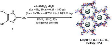 | ||
| Scheme 1 In situ synthesis of single co-doped Eu@IFP-1a–d, Tb@IFP-1a–d and double co-doped EuTb@IFP-1a–d. | ||
| IFP-1 material co-doped with lanthanides | Equivalents of | Atom% (product)b | |||
|---|---|---|---|---|---|
| Eu(NO3)3·6H2Oa | Tb(NO3)3·5H2Oa | Eu | Tb | Zn | |
| a Referred to the equivalents of Zn(NO3)2·4H2O employed in the synthesis. b Atom%, referred to the metal content; determined by ICP-OES. | |||||
| Eu@IFP-1a | 0.25 | 0.02 ± 0.01 | 99.98 ± 0.01 | ||
| Eu@IFP-1b | 0.50 | 0.03 ± 0.02 | 99.97 ± 0.02 | ||
| Eu@IFP-1c | 0.75 | 0.48 ± 0.06 | 99.52 ± 0.06 | ||
| Eu@IFP-1d | 1.00 | 1.04 ± 0.06 | 98.96 ± 0.06 | ||
| Tb@IFP-1a | 0.25 | 0.07 ± 0.02 | 99.93 ± 0.02 | ||
| Tb@IFP-1b | 0.50 | 0.11 ± 0.01 | 99.89 ± 0.01 | ||
| Tb@IFP-1c | 0.75 | 0.10 ± 0.03 | 99.90 ± 0.03 | ||
| Tb@IFP-1d | 1.00 | 0.16 ± 0.01 | 99.84 ± 0.01 | ||
| EuTb@IFP-1a | 0.25 | 0.25 | 0.04 ± 0.02 | 0.04 ± 0.01 | 99.93 ± 0.03 |
| EuTb@IFP-1b | 0.50 | 0.50 | 0.10 ± 0.03 | 0.11 ± 0.02 | 99.80 ± 0.05 |
| EuTb@IFP-1c | 0.75 | 0.75 | 0.91 ± 0.56 | 0.91 ± 0.54 | 98.18 ± 1.10 |
| EuTb@IFP-1d | 1.00 | 1.00 | 7.16 ± 0.24 | 6.76 ± 0.19 | 86.07 ± 0.42 |
3 Results and discussion
Structure determination
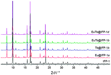
The synthesis of luminescent co-doped MOFs is usually based on the statistic replacement of a certain amount of metal ions as connectivity centers by luminescent ions like Ln3+ during MOF formation.9 Statistic replacement is thereby fundamentally dependent on a match between the two different metal ions in parameters like ionic radii, valence and chemical reactivity. For a potential co-doping of IFP-1 with lanthanide ions, these parameters do not match with Zn2+.15 Accordingly, also options like the formation of heterobimetallic compounds or the utilization of the pore system had to be investigated. On the other hand, the approach of in situ ligand synthesis simultaneous to the MOF formation seemed promising to immobilize highly charged ions within the pore system and to thereby avoid a postsynthetic treatment hindered by electrostatic interactions. For the intercalation of lanthanide ions into the MOF pores, the solvothermal reactions of the linker-precursor 4,5-dicyano-2-methylimidazole ( 1) and Zn(NO3)2·4H2O were carried out together with different equivalents of nitrates of europium and terbium (Scheme 1 and Table 1).Ln@IFP-1a–d (Ln = Eu or Tb) and EuTb@IFP-1a–d with amounts of lanthanides up to 14.0 atom% display the PXRD patterns identical to IFP-1 without non-indexed additional reflections (see Fig. 1 for examples and the ESI† details). To get further insights into the real structures of the activated Eu@IFP-1 and Tb@IFP-1 samples, we performed a combination of electron microscopy (SEM) and electron dispersive X-ray spectroscopy (EDX). Eu-elemental mapping shows a homogenous distribution of Eu3+ for an Eu-content lower than 0.50 atom% (e.g. Eu@IFP-1c; Fig. S8 in ESI†).
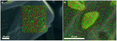
The Eu- and Tb-elemental mappings of EuTb@IFP-1b also indicate a uniform distribution of lanthanides (Fig. 2a). At higher Eu-contents, the SEM image and the Eu-elemental mapping revealed that additional microcrystals of Eu(HCOO)3 were formed (e.g. for 1.04 atom% (Eu@IFP-1d), Fig. S8, ESI†). This is also observed for the referring Eu/Tb co-doped materials. Elemental mapping of EuTb@IFP-1d depicts microcrystals of mixed EuTb(HCOO)3 deposited on the surface of an IFP-1 crystal (Fig. 2b). It can be anticipated that this microscopic difference illustrates the border of homogenous doping of the pore system for EuTb@IFP-1b and inhomogeneous doping for EuTb@IFP-1d, as only the latter shows mixed EuTb(HCOO)3 on the outside of the MOF crystals. The microscopic formation of the secondary phase can be attributed to the decomposition of DMF to formates. It is intriguing that the border of homogenous doping of the MOF cannot be observed by PXRD patterns of Ln@IPF-1, as the method is not suitable to determine very low amounts of secondary phases. Instead combination with other microscopic methods, as done here by SEM and EDX is essential for such modifications of MOFs in order to determine the correct characteristics. Apparently, PXRD can only determine the reflections of Ln(HCOO)3 at much higher concentrations. We therefore also carried out TG-MS measurements to identify Ln(HCOO)3 (see ESI† for details). We selected some of these doped materials for the details of gas sorption and fluorescence studies.
Sorption and porosity
In order to investigate the dependence of doping with lanthanide ions on the microporosity of IFP-1, physisorption experiments were carried out with N2 at 77 K on non-doped IFP-1 and frameworks homogenously doped with Eu3+ (Eu@IFP-1c), Tb3+ (Tb@IFP-1d) and Eu3+ together with Tb3+ (EuTb@IFP-1b), as well as on the MOF material showing the start of microscopic phase separation at a higher dopant degree by formation of EuTb(HCOO)3 on the surface of EuTb@IFP-1d. For further comparison, sorption experiments were also carried out with CO2 at 195 K on non-doped IFP-1 and Eu@IFP-1c. Specific surface areas were estimated by the use of adsorption isotherms for both N2 and CO2 utilizing the Brunauer–Emmet–Teller model (BET).Adsorption and desorption isotherms indicate microporosity for IFP-1, Eu@IFP-1c and Tb@IFP-1d of the same magnitude, for both N2 and CO2 sorption (Fig. 3). The full microporosity of the IFP-1 framework is retained upon doping with lanthanide ions, as long as no phase separation is observed (Table 2).
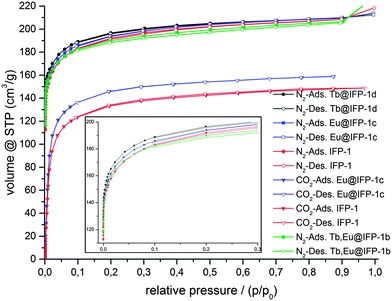 | ||
| Fig. 3 Adsorption (closed symbols) and desorption isotherms (open symbols) for N2 sorption at 77 K and CO2 at 195 K on IFP-1, homogenously doped Eu@IFP-1c, Tb@IFP-1d and EuTb@IFP-1b. | ||
| Sample | Surface area (BET) (m2 g−1) | Total pore volume (cm3 g−1) |
|---|---|---|
| N2 on IFP-1 | 737 | 0.33 |
| N2 on Eu@IFP-1c | 758 | 0.33 |
| N2 on Tb@IFP-1d | 745 | 0.33 |
| N2 on EuTb@IFP-1b | 702 | 0.31 |
| N2 on EuTb@IFP-1d | 633 | 0.28 |
| CO2 on IFP-1 | 736 | 0.28 |
| CO2 on Eu@IFP-1b | 768 | 0.30 |
For dopant degrees lower than 0.50 atom% of Ln3+ ions, no blockage of pores is observed besides the equilibration hindrance, which should be a sign for homogenous doping that is not only on the outer surface of the MOF, as this would lead to blockage of pores and a loss or stronger reduction of the inner surface. Accordingly, the surface investigations also assume that Eu@IFP-1c, Tb@IFP-1d and EuTb@IFP-1b are homogenously doped porous MOF phosphors. Observed deviations in the surface area between IFP-1 and Ln3+-doped IFP can mostly be addressed to influences of synthesis conditions. Hence, the in situ loading of microporous IFP-1 can be successfully carried out without diminishing the porosity of the MOF.
Non-doped IFP-1 shows a total uptake of 208 cm3 g−1 for N2 and 148 cm3 g−1 for CO2, while doped Eu@IFP-1c and Tb@IFP-1d show total uptakes of 210 cm3 g−1 for N2 each, as well as 159 cm3 g−1 of CO2 on Eu@IFP-1-c (at relative pressures close to unity). This indicates comparable inner surface areas for non-doped IFP-1 and all homogenously low-doped frameworks investigated (Table 2) despite the different analyte temperatures.
For dopant concentrations higher than 1.00 atom% the gas uptake decreases, as the additional phases of Ln(HCOO)3 are deposited as microcrystals on the outer surface of the homogenous Ln-doped IFP. Even though on a μm scale, they are large enough to block channels of the pore system, as shown for EuTb@IFP-1d. This sealing-off of some part of MOF micropores reduces the inner surface and thus the gas uptake. For an amount of 14 atom% of Eu3+ and Tb3+ ions, as determined for EuTb@IFP-1d, the observed reduction of the specific surface area is about 14%, equaling 104 cm3 g−1 and corresponding to a reduced specific surface area of 633 m2 g−1 for N2. The option to achieve both, homogenous doping as well as phase separation, further supports the idea that the pore system of IFP-1 can be utilized for doping, but that there are certain limits for the homogenous co-doping of IFP-1 with lanthanide ions.
Because of the chemical and thermal stability of the intrinsic one-dimensional channel structure, the zinc constituted IFP-1 is also formed in the presence of nitrates of Eu3+ and Tb3+. It could be anticipated that the lanthanide ions are encapsulated into the channels of IFP-1 and not statistically substituting the connectivity centers, as there is a large mismatch between Zn2+ and Ln3+ in ionic radii and charge. The presence of the imidate and amide groups of the channel walls and thus the inner surface of IFP-1 enhances the polarization and hydrophilic characteristics of the channels and allows interaction with lanthanide ions. Low-doped Ln@IFP-1 contains only small amounts of Ln3+ ions, which introduce an imbalance in the electronic equilibrium of the network that needs to be balanced by a corresponding amount of anions. Based on the analytics described above, we assume an additional intercalation of formate anions. Further electronic exchange for charge equilibration at functional groups is possible inside the channels of the framework.
Photoluminescence
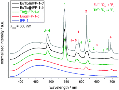
Non-doped IFP-1 exhibits a weak photoluminescence due to a broad, blue emission band ranging from 375 nm to 700 nm at RT with its maximum at λmax = 463 nm (λex = 360 nm) (Fig. 4). The excitation band in the range of 300 nm to 425 nm is also broad with its maximum at λmax = 355 nm (λem = 463 nm) and a shoulder at around λshoulder ∼ 430 nm (Fig. S13, ESI†). Doping of the IFP framework by the in situ available Eu3+ and Tb3+ ions during the formation reaction introduces additional luminescence properties. Besides the framework fluorescence, the lanthanide containing materials, e.g. Eu@IFP-1c and Tb@IFP-1d, exhibit additional, characteristic lanthanide emission bands.16,17 The additional emission bands originate from the corresponding metal-centered 4f–4f transitions of the respective trivalent lanthanide ions in Ln3+-doped IFP-1. The emission can be observed by excitation of the framework ligands, which act as sensitizers for the lanthanide ions establishing an antenna effect18 (Fig. 4), indicating an energy transfer between the IFP-backbone and the Ln3+-dopants. The direct excitation of the Ln3+ 4f–4f transitions is also possible (Fig. 5), but weak compared to the antenna effect. Accordingly, the excitation spectra of doped Eu@IFP-1c and Tb@IFP-1d are very similar to the excitation spectra of non-doped IFP-1 (Fig. S13 at ESI†) because of the low extinction coefficients of the lanthanide ions compared to the framework backbone.For Tb@IFP-1d, the typical Tb3+-transitions 5D4 → 7FJ (J = 6–0) are observed, and for Eu@IFP-1c the Eu3+-transitions 5D0 → 7FJ (J = 0–4) are detected. After introduction of the Eu3+ or Tb3+ ions into the framework, the intensity of the broad emission band of the framework itself does not change significantly. Comparing the intensities of the sensitized Ln3+-emission, the Tb3+-containing compound Tb@IFP-1d shows a more intensive 4f–4f emission than Eu@IFP-1c (Fig. 4). Excitation of co-doped IFP with Eu3+ and Tb3+ (Fig. 4, EuTb@IFP-1b and EuTb@IFP-1d) leads to the blue framework emission along with the characteristic green and orange-red emissions of Tb3+ and Eu3+, respectively.
Framework backbone centered emission and Ln3+-centered emission can also be distinguished by investigations of the decay time of the photoluminescence processes. The decay time of the fluorescence process is on the low nanosecond scale for the broad band emission of the ligand (IFP-1: τ = 0.33(1)–5.74(20) ns, Eu@IFP-1c: τ = 0.13(1)–4.22(14) ns, and Tb@IFP-1d: τ = 0.04(2)–4.82(16) ns), which is much faster than the luminescence decay times found for Eu3+ and Tb3+ (Eu@IFP-1c: τ = 314(13)–1337(117) μs, and Tb@IFP-1d: τ = 580(33)–1062(60) μs; see also Table S6, ESI†).
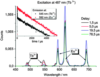
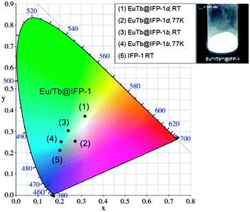
In the Eu3+- and Tb3+-co-doped samples, in addition to the antenna effect of the ligand, a metal-to-metal energy transfer from Tb3+ to Eu3+ was detected for the materials EuTb@IFP-1b and EuTb@IFP-1d. This energy transfer is more effective for higher lanthanide loadings as the efficiency of the energy transfer depends on the average distances between the donor and the acceptor (Fig. 4). Given a random distribution of dopants the distance between Eu3+ and Tb3+ is inversely proportional to the metal loading. The Tb3+ → Eu3+ metal-to-metal energy transfer is proven by detection of Eu3+ emission after selective excitation of Tb3+ (λex = 478 nm) and the observed luminescence decay kinetics of Tb3+ and Eu3+, as shown by site selective PL spectroscopy (Fig. 5). This energy transfer is a great tool to fine-tune the color point and thus the chromaticity of the white light emitting materials. Higher Eu3+ emission intensities lead to a warmer white light emission (vide infra).
White light emission properties
As stated, the organic part of the framework contributes a broad band emission in the blue spectral range, Tb3+ and Eu3+ add a green and a red emission component, respectively, to the EuTb-co-doped IFP-1 materials. Altogether this enables the emission of white light by EuTb@IFP-1, as the materials (as shown for EuTb@IFP-1b and EuTb@IFP-1d) exhibit a combination of the framework fluorescence and the luminescence of Tb3+ as well as Eu3+ (Fig. 4 and 5). The three color emitter EuTb@IFP-1 thereby meets today's standards of color rendering of LED phosphors and exceeds the recent two color emitting MOFs.10,19 Compared to IFP-1 co-doped with one lanthanide ion, only, like Eu@IFP-1b and d, a significant increase in Eu3+-luminescence intensity is observed contributing to the overall white emission color of the materials EuTb@IFP-1b and EuTb@IFP-1d (Fig. 4 and 5). It is remarkable that EuTb@IFP-1 shows a tunable chromaticity point with varying dopant concentrations (Fig. 6 and Table S5, ESI†).In addition, the temperature can also be used to influence the color point of the materials. One reason is a reduction of the blue ligand emission upon increasing temperature. Consequently, the overall white color temperature of the co-doped IFP is also temperature dependent (Fig. 6). At 77 K, EuTb@IFP-1d emits a cold white light, which turns into a warm white light at RT. Hence the warmth of the white color could also be used for temperature sensing, as recently shown for Eu0.0069Tb0.9931–DMBDC (DMBDC: 2,5-dimethoxy-1,4-benzene-dicarboxylate).11a The color point is moved further to a warmer color by larger amounts of lanthanide ions. This behavior can be explained by smaller average Tb3+–Eu3+ distances and therefore a more effective metal-to-metal energy transfer leading to an increased contribution of the red Eu3+ emission to the white light (Fig. 6). It is intriguing that besides the homogenous distribution of the lanthanide ions in the pore system, heterogeneous composites of EuTb@IFP-1 with lanthanide formate crystals on the outer surface can also have beneficial effects on the tuning of the warmth of the white light emission. This further underlines the importance to distinguish between homogenous loading of the pore system of the MOF and a utilization of the outer surface for an understanding of the processes observed.
In order to understand the coordination environment and position of Ln3+-dopants incorporated into the IFP materials during synthesis, high resolution Eu3+-spectra were recorded. At ultra-low temperatures of 4 K, processes contributing to the spectral broadening of electronic transitions (inhomogeneous broadening) are minimized and small differences in the electronic spectra of different chemical species or chemical species in different environments and coordination can be resolved. Site selective Eu3+-spectroscopy using a narrow bandwidth dye laser as an excitation light source offers a unique possibility to probe Eu3+ ions and distinguish their different chemical environments. Due to the non-degenerate ground (7F0) and first excited states (5D0) of Eu3+, the corresponding electronic transition of a single species of Eu3+ ions consists of only one peak, which is not split by the crystal field. The energy of the absorption and emission is dependent on the strength of the crystal field and differs for different Eu3+ species (nephelauxetic effect). Subsequently, different chemical species present in one single sample can be probed individually. Moreover, the obtained Stark-splitting patterns of the lower energy transitions 5D0 → 7F1–7F6 contain complementary information on the individual chemical species, e.g., the symmetry and homogeneity of a distinct lattice site. We chose different Eu@IFP-1 samples to elaborate the study on the location and coordination environment of the lanthanide ions.
Homogenously doped Eu@IFP-1b and EuTb@IFP-1b (both as-synthesized) show no sharp, distinct emission lines indicating that the probed Eu3+ ions are located in non-homogeneous binding environments (Fig. 7) and not on a distinct crystallographic site, if they replaced the connectivity centers of IFP-1. The broad, unresolved luminescence originates from Eu3+ ions distributed over a variety of slightly different chemical environments in the sample, which would be possible inside the pores of the MOF. Based on the luminescence spectra no indication of a separate phase including formate is found, which is in good agreement with the other analytical results (Fig. S8b at ESI† and Fig. 2a, respectively).
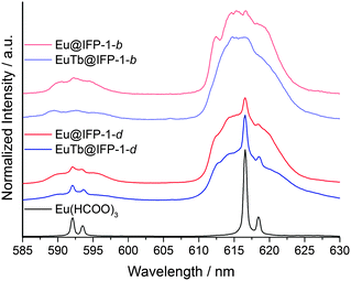 | ||
| Fig. 7 Emission spectra of Eu(HCOO)3, homogenous/heterogeneous Ln3+ co-doped Eu@IPF-1d and EuTb@IPF-1d, as well as homogenous doped Eu@IFP-1b and EuTb@IPF-1b (all as-synthesized) after excitation at λex = 579.60 nm, the excitation maximum of Eu(HCOO)3. All spectra are extracted from the total luminescence spectra (as shown in Fig. 6) after a scan over the 7F0–5D0 transition at T = 4 K. | ||
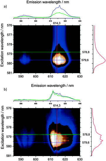
Site-selective excitation of the 5D0 → 7F0 transition of the various doped Eu@IFP-1d and EuTb@IFP-1d materials (both as synthesized) yielded luminescence spectra showing one Eu3+ species with a two-fold crystal field splitting of the 5D0–7F1 and 5D0–7F2 transitions along with the same broad luminescence without well-resolved Stark-splitting (Fig. 7).
Comparison with a Eu(HCOO)3 reference shows that the sharp, two-fold split luminescence lines can be attributed to the formation of small domains of crystalline Eu(HCOO)3. This again is in very good agreement with the results obtained from SEM and EDX (Fig. S8d, ESI†) and shows that the region of homogenous doping can also be spectroscopically identified by ultra-low temperature PL spectroscopy.
Removal of solvent molecules by heating the Eu@IFP-1d samples to 200 °C in a vacuum of 1 mbar was performed until the sample mass was constant. In the total emission spectra (Fig. 8) two things can be seen: (i) the sharp emission peaks attributed to the formate phase (λex = 579.6 nm, vide supra) are preserved and (ii) alteration in shape/structure of the broad excitation and emission bands (Fig. 8). Alterations in the spectra always originate from alterations in the crystal field experienced by the Eu3+-dopants. The changes in the broad excitation and emission bands suggest that the Eu3+ ions are located inside the channels of IFP-1 from which the solvent escapes, as opposed to an additional (formate) phase and/or the outside surface of the MOF. The changes in the luminescence signature upon removal of solvent molecules from the MOF framework channels, at the same time, strongly support the previously concluded saturation of the coordination spheres of Eu3+ by solvent molecules.
Although the emission and excitation bands appear to be overall broadened upon the removal of solvent molecules indicating greater variations in the crystal fields, the increased structure in the emission and excitation spectra is clearly visible. The structure in the spectra can be interpreted as more distinct, more crystalline-like crystal sites, where greater numbers of Eu3+ ions have very similar coordination spheres and therefore crystal fields.
The colored intensity plots of the total luminescence allow a rough estimation of the number of different lattice sites, meaning groups of Eu3+-dopants experiencing an identical crystal field. About four groups of identical Eu3+ ions can be excited in a very narrow bandwidth between 578.8 nm and 579.6 nm for the activated samples, each group showing different emission intensity patterns (Fig. 8b). It seems, due to the relatively rigid structure of the MOF, that there is a limited amount of symmetries that can stabilize the depleted coordination spheres of Eu3+-dopants after removal of solvent molecules, thus explaining the sharpened peaks. This indicates favored positions of the Ln3+ ions within the pore system, interacting with the functional groups of the linker. Trapping of Eu3+ and Tb3+ ions was just recently shown for the MOF Zn4O(L)1.5, L = 6,6′-(2,2-bis((6-carboxy-naphthalen-2-yloxy)methyl)propane-1,3-diyl)bis(oxy)di-2-naphthoate showing a color tuning of the luminescence from green to red at different Eu/Tb ratios.20a Capture of Ln3+-ions in MOF pores was also used for the detection of Ln3+ by uptake of the ions Eu3+ and Tb3+ into IFMC, a zinc nitrate MOF with tricarboxylate ligands based on a central tripodal ether group, to give Eu@IFMC-10 and Tb@IFMC-10.20b
For EuTb@IFP-1, indirect excitation of europium in the UV spectral range using framework sensitization supports the interpretation that the unstructured, broad emission is caused by Ln3+ ions located inside the channels of the MOF material. The antenna effect depends on the close proximity of the metal ion and the sensitizer (MOF channel walls coordinating Ln3+). Thereby, site selective photoluminescence spectroscopy and total emission spectra give vital insights into the nature of the lanthanide uptake in the pores and also corroborate the formation of lanthanide formate side phases from a certain Ln-amount, as the luminescence of both phenomena can be clearly distinguished.
Conclusions
To summarize, the formation of a white light emitting MOF is achieved by simultaneous co-doping of IFP-1 with Tb3+ and Eu3+ during the in situ formation of the ligand and the MOF. This in situ co-doping with trivalent Ln3+ ions enables luminescent MOFs with almost identical porosity to the non-doped framework. The three emission colors blue, green and red are therefore combined in one emitter. The luminescence of the IFP-1 backbone together with 4f-emission of the lanthanide ions add to a three-color white light emitting MOF that shows the effective white light emission in comparison with the previously known one- and two-color white light emitters. The photoluminescence is supported by ligand-to-metal and metal-to-metal energy transfers, with the color of the white light emission being temperature and Ln3+ concentration dependent. A more bluish chromaticity is observed for cooling to 77 K and for low dopant degrees, whereas a warmer white light is emitted at RT for high dopant amounts. This effect can be potentially used for spectroscopic temperature sensing. The lanthanide ions do not replace zinc ions as connectivity centers but are intercalated into the pore system of the IFP-1 MOF during synthesis without a structure directing effect. The uptake is homogenous with no detectable differences in distribution if the final dopant degree is lower than 1.0 atom% referred to the amount of Zn2+. At higher dopant degrees, phase formation of lanthanide formates from decomposition of the solvent DMF starts to occur in addition to the intercalation into the MOF. The lanthanide formates can be characterized as the secondary crystalline phase at the outer surface of the MOF particles and limit the homogenous region of co-doping. Intercalated Ln3+ ions and lanthanide formates can be clearly distinguished by means of photoluminescence spectroscopy, SEM/EDX and sorption experiments. Eu- and Tb-formates on the surface can be beneficially used to further tune the chromaticity of the MOF in a composite relationship. The luminescent MOFs Ln@IFP-1 retain their microporosity upon loading with luminescence centers regarding sorption of N2 at 77 K and CO2 at 195 K in the homogenous region of co-doping. To the best of our knowledge, EuTb@IFP-1d is the first example of a white light emitting MOF with proven porosity in combination with luminescence centers inside the pore system and non-substituting connectivity centers of the MOF.Acknowledgements
The authors thank Dr C. Günter (Universität Potsdam) for help with X-ray powder diffraction measurements, Dr M. Neumann for TG-MS measurements, S. Lubahn (Universität Potsdam) for the ICP-OES measurements and Y. Linde (Universität Potsdam) for the C, H, and N elemental analysis. This work is financially supported by the Priority Program 1362 of the German Research Foundation on “Metal–Organic Frameworks” and the Dr Klaus-Römer foundation.Notes and references
- (a) J. L. C. Rowsell and O. M. Yaghi, Microporous Mesoporous Mater., 2004, 73, 3 CrossRef CAS PubMed; (b) O. M. Yaghi, G. Li and H. Li, Nature, 1995, 378, 703 CrossRef CAS; (c) G. J. Férey, C. Mellot-Draznieks, C. Serre and F. Millange, Acc. Chem. Res., 2005, 38, 217 CrossRef PubMed; (d) S. L. James, Chem. Soc. Rev., 2003, 32, 276 RSC; (e) S. Meek, J. Greathouse and M. Allendorf, Adv. Mater., 2011, 23, 249 CrossRef CAS PubMed; (f) M. Li, D. Li, M. O'Keeffe and O. M. Yaghi, Chem. Rev., 2014, 114, 1343 CrossRef CAS PubMed.
- (a) S. Ma and H.-C. Zhou, Chem. Commun., 2010, 46, 44 RSC; (b) K. Sumida, D. L. Rogow, J. A. Mason, T. M. McDonald, E. D. Bloch, Z. R. Herm, T.-H. Bae and J. R. Long, Chem. Rev., 2012, 112, 724 CrossRef CAS PubMed; (c) M. P. Suh, H. J. Paark, T. K. Prasad and D.-W. Lim, Chem. Rev., 2012, 112, 782 CrossRef CAS PubMed; (d) L. J. Murray, M. Dinč and J. R. Long, Chem. Soc. Rev., 2009, 38, 1294 RSC; (e) A. U. Czaja, N. Trukhan and U. Müller, Chem. Soc. Rev., 2009, 38, 1284 RSC; (f) T. R. Cook, Y.-R. Zheng and P. J. Stang, Chem. Rev., 2013, 113, 734 CrossRef CAS PubMed.
- (a) L. Pan, D. H. Olson, L. R. Ciemnolonski, R. Heddy and J. Li, Angew. Chem., Int. Ed., 2006, 45, 616 CrossRef CAS PubMed; (b) J.-R. Li, J. Sculley and H.-C. Zhou, Chem. Rev., 2012, 112, 869 CrossRef CAS PubMed; (c) J.-R. Li, R. J. Kuppler and H.-C. Zhou, Chem. Soc. Rev., 2009, 38, 1477 RSC.
- (a) A. M. Shultz, O. K. Farha, J. T. Hupp and S. T. Nguyen, J. Am. Chem. Soc., 2009, 131, 4204 CrossRef CAS PubMed; (b) D. J. Lun, G. I. N. Waterhouse and S. G. Telfer, J. Am. Chem. Soc., 2011, 133, 5806 CrossRef CAS PubMed; (c) R. E. Morris and X. Bu, Nat. Chem., 2010, 2, 353 CrossRef CAS PubMed.
- (a) X. L. Qi, R. B. Lin, Q. Chen, J. B. Lin, J.-P. Zhang and X.-M. Chen, Chem. Sci., 2011, 2, 2214 RSC; (b) Y.-N. Wu, F. Li, W. Zhu, J. Cui, C.-A. Tao, C. Lin, P. M. Hannam and G. Li, Angew. Chem., Int. Ed., 2011, 50, 12518 CrossRef CAS PubMed.
- (a) P. Horcajada, C. Serre, M. Vallet-Regi, M. Sebban, F. Taulelle and G. J. Férey, Angew. Chem., Int. Ed., 2006, 45, 5974 CrossRef CAS PubMed; (b) P. Horcajada, C. Serre, G. Maurin, N. A. Ramsahye, F. Balas, M. Vallet-Regi, M. Sebban, F. Taulelle and G. J. Férey, J. Am. Chem. Soc., 2008, 130, 6774 CrossRef CAS PubMed; (c) S. Keskin and S. Kizilel, Ind. Eng. Chem. Res., 2011, 50, 1799 CrossRef CAS.
- (a) Z. Hu, B. J. Deibert and J. Li, Chem. Soc. Rev., 2014, 43, 5815 RSC; (b) Q.-Y. Liu, Y.-L. Wang, N. Zhang, Y.-L. Jiang, J.-J. Wie and F. Luo, Cryst. Growth Des., 2011, 11, 3717 CrossRef CAS; (c) K. Liu, H. You, Y. Zheng, G. Jia, L. Zhang, Y. Huang, M. Yang, Y. Song and H. Zhang, CrystEngComm, 2009, 11, 2622 RSC; (d) H. Zhang, N. Li, C. Tian, T. Liu, F. Du, P. Lin, Z. Li and S. Du, Cryst. Growth Des., 2012, 12, 670 CrossRef CAS; (e) C. J. Höller, M. Mai, C. Feldmann and K. Müller-Buschbaum, Dalton Trans., 2010, 39, 461 RSC.
- (a) M. D. Allendorf, C. A. Bauer, R. K. Bhakta and R. J. T. Houk, Chem. Soc. Rev., 2009, 38, 1330 RSC; (b) J. Rocha, L. D. Carlos, F. A. Almeida Paz and D. Ananias, Chem. Soc. Rev., 2011, 40, 926 RSC; (c) Y. Cui, Y. Yue, G. Qian and B. Chen, Chem. Rev., 2012, 112, 1126 CrossRef CAS PubMed; (d) N. Stock and S. Biswas, Chem. Rev., 2012, 112, 933 CrossRef CAS PubMed; (e) J. Heine and K. Müller-Buschbaum, Chem. Soc. Rev., 2013, 42, 9232 RSC; (f) Z. Hu, B. J. Deibert and J. Li, Chem. Soc. Rev., 2014, 43, 5815 RSC; (g) Y. Cui, B. Chen and G. Qian, Coord. Chem. Rev., 2014, 273, 76 CrossRef PubMed; (h) J. Lei, R. Qian, P. Ling, L. Cui and H. Ju, Trends Anal. Chem., 2014, 58, 71 CrossRef CAS PubMed; (i) C. Dey, T. Kundu, B. P. Biswal, A. Mallick and R. Banerjee, Acta Crystallogr., Sect. B: Struct. Sci., Cryst. Eng. Mater., 2014, 70, 3 CrossRef CAS PubMed; (j) D. Liu, K. Lu, C. Poon and W. Lin, Inorg. Chem., 2014, 53, 1916 CrossRef CAS PubMed; (k) Y. F. Chen, Y.-C. Ma and S.-M. Chen, Cryst. Growth Des., 2013, 13, 4154 CrossRef CAS.
- (a) P. Falcaro and S. Furukawa, Angew. Chem., 2012, 51, 8431 CrossRef CAS PubMed; (b) A. Zurawski, M. Mai, D. Baumann, C. Feldmann and K. Müller-Buschbaum, Chem. Commun., 2011, 47, 496 RSC; (c) P. R. Matthes, C. J. Höller, M. Mai, J. Heck, S. J. Sedlmaier, S. Schmiechen, C. Feldmann, W. Schnick and K. Müller-Buschbaum, J. Mater. Chem., 2012, 22, 10179 RSC; (d) Q. Tang, S. Liu, Y. Liu, D. He, J. Miao, X. Wang, Y. Ji and Z. Zheng, Inorg. Chem., 2014, 53, 289 CrossRef CAS PubMed; (e) V. Haquin, M. Etienne, C. Daiguebonne, S. Freslon, G. Calvez, K. Bernot, L. Le Pollès, S. E. Ashbrook, M. R. Mitchell, J.-C. Bünzli, S. V. Eliseeva and O. Guillou, Eur. J. Inorg. Chem., 2013, 3464 CrossRef CAS PubMed; (f) H. Zhang, X. Shan, L. Zhou, P. Lin, R. Li, E. Ma, X. Guoab and S. Du, J. Mater. Chem. C, 2013, 1, 888 RSC; (g) J.-C. Rybak, M. Hailmann, P. R. Matthes, A. Zurawski, J. Nitsch, A. Steffen, J. G. Heck, C. Feldmann, S. Götzendörfer, J. Meinhardt, G. Sextl, H. Kohlmann, S. J. Sedlmaier, W. Schnick and K. Müller-Buschbaum, J. Am. Chem. Soc., 2013, 135, 6896 CrossRef CAS PubMed; (h) H. Zhang, X. Shan, Z. Ma, L. Zhou, M. Zhang, P. Lin, S. Hu, E. Ma, R. Li and S. Du, J. Mater. Chem. C, 2014, 2, 1367 RSC; (i) Y. Wang, Y.-Y. Liu and J.-F. Ma, Chem. – Eur. J., 2013, 19, 14591 CrossRef CAS PubMed.
- D. F. Sava, L. E. S. Rohwer, M. A. Rodriguez and T. M. Nenoff, J. Am. Chem. Soc., 2012, 134, 3983 CrossRef CAS PubMed.
- (a) Q. Tang, S. Liu, Y. Liu, D. He, J. Miao, X. Wang, Y. Ji and Z. Zheng, Inorg. Chem., 2014, 53, 289 CrossRef CAS PubMed; (b) A. Ablet, S.-M. Li, W. Cao, X.-J. Zheng, W.-T. Wong and L.-P. Jin, Chem. – Asian J., 2013, 8, 95 CrossRef CAS PubMed; (c) Y. Liu, M. Pan, Q.-Y. Yang, L. Fu, K. Li, S.-C. Wei and C.-Y. Su, Chem. Mater., 2012, 24, 1954 CrossRef CAS; (d) F. Luo, M.-S. Wang, M.-B. Luo, G.-M. Sun, Y.-M. Song, P.-X. Lia and G.-C. Guo, Chem. Commun., 2012, 48, 5989 RSC; (e) C.-Y. Sun, X.-L. Wang, X. Zhang, C. Qin, P. Li, Z.-M. Su, D.-X. Zhu, G.-G. Shan, K.-Z. Shao, H. Wu and J. Li, Nat. Commun., 2013, 4, 2717 Search PubMed; (f) L. V. Meyer, F. Schönfeld and K. Müller-Buschbaum, Chem. Commun., 2014, 50, 8093 RSC.
- (a) S. P. Nakamura, Proc. SPIE, 1997, 3002, 26 CrossRef CAS PubMed; (b) R. Mueller-Mach, G. O. Mueller, M. R. Krames and T. Trottier, IEEE J. Sel. Top. Quantum Electron., 2002, 8, 339 CrossRef CAS.
- (a) R. Mueller-Mach, G. O. Mueller, M. R. Krames, H. A. Hoppe, F. Stadler, W. Schnick, T. Juestel and P. Schmidt, Phys. Status Solidi A, 2005, 202, 1727 CrossRef CAS PubMed; (b) E. F. Schubert, Light-emitting diodes, Cambridge University Press, Cambridge, New York, 2006 Search PubMed; (c) V. Bachmann, C. Ronda, O. Oeckler, W. Schnick and A. Meijerink, Chem. Mater., 2009, 21, 316 CrossRef CAS; (d) T. Nägele, LED Professional Rev., 2008, 10, 1 CrossRef; (e) W. Lv, Y. Jia, Q. Zhao, W. Lü, M. Jiao, B. Shao and H. You, J. Phys. Chem. C, 2014, 118, 4649 CrossRef CAS; (f) Y. Zhang, D. Geng, X. Li, J. Fan, K. Li, H. Lian, M. Shang and J. Lin, J. Phys. Chem. C, 2014, 118, 17983 CrossRef CAS; (g) G. Li, C. C. Lin, W.-T. Chen, M. S. Molokeev, V. V. Atuchin, C.-Y. Chiang, W. Zhou, C.-W. Wang, W.-H. Li, H. S. Sheu, T.-S. Chan, C. Ma and R.-S. Liu, Chem. Mater., 2014, 26, 2991 CrossRef CAS.
- (a) F. Debatin, A. Thomas, A. Kelling, N. Hedin, Z. Bacsik, I. Senkovska, S. Kaskel, M. Junginger, H. Müller, U. Schilde, C. Jäger, A. Friedrich and H.-J. Holdt, Angew. Chem., Int. Ed., 2010, 49, 1258 CrossRef CAS PubMed; (b) F. Debatin, K. Behrens, J. Weber, I. A. Baburin, A. Thomas, J. Schmidt, I. Senkovska, S. Kaskel, A. Kelling, N. Hedin, Z. Bacsik, S. Leoni, G. Seifert, C. Jäger, C. Günter, U. Schilde, A. Friedrich and H.-J. Holdt, Chem. – Eur. J., 2012, 18, 11630 CrossRef CAS PubMed; (c) F. Debatin, J. Möllmer, S. S. Mondal, K. Behrens, A. Möller, R. Staudt, A. Thomas and H.-J. Holdt, J. Mater. Chem., 2012, 22, 10221 RSC; (d) S. S. Mondal, A. Bhunia, I. A. Baburin, C. Jäger, A. Kelling, U. Schilde, G. Seifert, C. Janiak and H.-J. Holdt, Chem. Commun., 2013, 49, 7599 RSC; (e) S. S. Mondal, S. Dey, I. A. Baburin, A. Kelling, U. Schilde, G. Seifert, C. Janiak and H.-J. Holdt, CrystEngComm, 2013, 15, 9394 RSC; (f) S. S. Mondal, A. Bhunia, S. Demeshko, A. Kelling, U. Schilde, C. Janiak and H.-J. Holdt, CrystEngComm, 2014, 16, 39 RSC; (g) S. S. Mondal, A. Bhunia, A. Kelling, U. Schilde, C. Janiak and H.-J. Holdt, Chem. Commun., 2014, 50, 5441 RSC.
- (a) Y.-Q. Sun, J. Zhang, Y.-M. Chen and G.-Y. Yang, Angew. Chem., Int. Ed., 2005, 44, 5814 CrossRef CAS PubMed; (b) Y.-Q. Sun, J. Zang and G.-Y. Yang, Chem. Commun., 2006, 4700 RSC; (c) S.-R. Zheng, S.-L. Cai, Q.-Y. Yang, T.-T. Xia, J. Fan and W.-G. Zhang, Inorg. Chem. Commun., 2011, 14, 826 CrossRef CAS PubMed; (d) Z.-H. Zhang, T.-A. Okamura, Y. Hasegawa, H. Kawaguchi, L. Y. Kong, W.-Y. Sun and N. Ueyama, Inorg. Chem., 2005, 44, 6219 CrossRef CAS PubMed; (e) S.-M. Li, X. J. Zheng, D.-Q. Yuan, A. Ablet and L.-P. Jin, Inorg. Chem., 2012, 51, 1201 CrossRef CAS PubMed; (f) R.-L. Chen, X.-Y. Chen, S.-R. Zheng, J. Fan and W.-G. Zhang, Cryst. Growth Des., 2013, 13, 4428 CrossRef CAS; (g) Q. Tang, S. Liu, Y. Liu, D. He, J. Miao, X. Wang, Y. Ji and Z. Zheng, Inorg. Chem., 2014, 53, 289 CrossRef CAS PubMed.
- (a) J.-C. G. Bünzli and S. V. Eliseeva, in Basics of Lanthanide Photophysics, Fluorescence: Lanthanide Luminescence: Photophysical, Analytical and Biological Aspects, ed. O. S. Wolfbeis and M. Hof, Springer Verlag, Berlin, 2011, vol. 7 Search PubMed; (b) G. H. Dieke, Spectra and energy levels of rare earth ions in crystals, Interscience Publishers, New York, 1968 Search PubMed.
- (a) J.-C. G. Bünzli and C. Piguet, Chem. Soc. Rev., 2005, 34, 1048 RSC; (b) K. Binnemans, Chem. Rev., 2009, 109, 4283 CrossRef CAS PubMed; (c) S. V. Eliseeva and J.-C. G. Bünzli, Chem. Soc. Rev., 2010, 39, 189 RSC.
- (a) G. F. de Sá, O. L. Malta, C. de Mello Donegá, A. M. Simas, R. L. Longo, P. A. Santa-Cruz and E. F. da Silva Jr., Coord. Chem. Rev., 2000, 196, 165 CrossRef; (b) F. R. Gonçalves e Silva, O. L. Malta, C. Reinhard, H.-U. Güdel, C. Piguet, J. E. Moser and J.-C. G. Bünzli, J. Phys. Chem. A, 2002, 106, 1670 CrossRef; (c) H. Guo, Y. Zhu, S. Qiu, J. A. Lercher and H. Zhang, Adv. Mater., 2010, 22, 4190 CrossRef CAS PubMed.
- A. Ablet, S.-M. Li, W. Cao, X.-J. Zheng, W.-T. Wong and L.-P. Jin, Chem. – Asian J., 2013, 8, 95 CrossRef CAS PubMed.
- (a) Y.-Q. Lan, H.-L. Jiang, S.-L. Li and Q. Xu, Adv. Mater., 2011, 23, 5015 CrossRef CAS PubMed; (b) L. Chen, K. Tan, Y.-Q. Lan, S.-L. Li, K.-Z. Shao and Z.-M. Su, Chem. Commun., 2012, 48, 5919 RSC.
Footnote |
| † Electronic supplementary information (ESI) available: Details of IR-spectroscopy, elemental analysis, ICP-OES, powder X-ray diffraction, scanning electron microscopy, energy-dispersive X-ray spectroscopy, thermogravimetric analysis, TG-MS, gas sorption, photoluminescence and decay investigation. See DOI: 10.1039/c4tc02919d |
| This journal is © The Royal Society of Chemistry 2015 |

