 Open Access Article
Creative Commons Attribution 3.0 Unported Licence
Multifunctional high strength and high energy epoxy composite structural supercapacitors with wet-dry operational stability†
Andrew S.
Westover
ab,
Bradly
Baer
ab,
Babatunde H.
Bello
a,
Haotian
Sun
a,
Landon
Oakes
ab,
Leon M.
Bellan
ab and
Cary L.
Pint
*ab
aDepartment of Mechanical Engineering, Vanderbilt University, Nashville, TN 37235, USA
bInterdisciplinary Materials Science Program, Vanderbilt University, Nashville, TN 37235, USA. E-mail: cary.l.pint@vanderbilt.edu
First published on 14th September 2015
Abstract
We demonstrate the fabrication of multifunctional structural supercapacitors that maintain energy storage capability under both mechanical stresses and water immersion. This is based on the infiltration of bisphenol A ionic liquid epoxy resin electrolytes infiltrated into nanoporous silicon interfaces that play the dual role of charge storage and mechanical reinforcement of the energy storage composite material. These structural composites maintain full energy storage capability (5–8 W h kg−1) under tensile stresses over 1 MPa, with nearly 100% energy retention after 4000 cycles. We observe this mechanical and charge storage performance to be preserved through extreme water immersion conditions in contrast to conventional polymer-based solid-state electrolytes that spontaneously lose mechanical integrity under water immersion conditions. As structural energy storage is required to simultaneously maintain mechanical integrity, store charge, and operate in unpackaged environments exposed to humidity and wet-dry conditions, we demonstrate the first device architecture capable of all these conditions while demonstrating energy capability near current packaged commercial supercapacitor devices.
Advances in energy storage materials have been the foundation for broad innovation in emerging technologies such as portable electronics, electric vehicles, and grid-scale energy systems in recent years. Systematic technological advancements in these areas require development of energy storage systems with higher energy density,1–5 higher power density,6–9 and lower costs,10–12 building on a conventional platform where energy storage devices are situated externally from the systems they power. In recent years, an emerging field of research has focused on multifunctional energy storage systems where energy storage can be built into energy conversion systems as well as wearable, flexible, or structural systems.13–21 In the specific case of structural energy storage systems, these systems must exhibit the basic requirement of simultaneously maintaining structural integrity and sustaining the ability to store and release energy. Unlike conventional energy storage analogues, structural energy storage materials have the potential to greatly reduce the weight of energy-using systems by multipurposing existent materials with energy storage, or to maintain the same weight and significantly enhance the total on-board energy storage capability of a system. This represents two key trajectories that are critical to advancing next-generation technological systems.
Due to the simplicity of the charge storage mechanism, reports on structural capacitive storage systems have emerged in recent years.22–29 Early efforts have demonstrated carbon fiber based epoxy composite electrodes that exhibit excellent mechanical properties with the capability to store charge (5–26 MPa of shear strength, and Young's modulus of up to 30 GPa).16,22–25,27 However, the use of carbon fibers is a bottleneck to achieve practical charge storage capability, as these materials exhibit surface area that is near 10![[thin space (1/6-em)]](https://www.rsc.org/images/entities/char_2009.gif) 000× lower than state-of-the-art nanomaterials for supercapacitors. Furthermore, combining high surface area materials with these templates leads to weakly coupled electrical–mechanical interfaces that challenge the load-bearing energy storage capability of the material. In previous studies on multifunctional energy storage, electrochemical and mechanical properties are tested and reported separately, and in some cases the mechanical properties of the full device are not assessed due to the use of liquid electrolytes.26 As charge storage in an electrochemical supercapacitor occurs at the electrode–electrolyte interface, which is the interface under stress in a structural energy storage device, multifunctional energy storage capability must be determined by the synergistic assessment of energy storage performance under mechanical stress.
000× lower than state-of-the-art nanomaterials for supercapacitors. Furthermore, combining high surface area materials with these templates leads to weakly coupled electrical–mechanical interfaces that challenge the load-bearing energy storage capability of the material. In previous studies on multifunctional energy storage, electrochemical and mechanical properties are tested and reported separately, and in some cases the mechanical properties of the full device are not assessed due to the use of liquid electrolytes.26 As charge storage in an electrochemical supercapacitor occurs at the electrode–electrolyte interface, which is the interface under stress in a structural energy storage device, multifunctional energy storage capability must be determined by the synergistic assessment of energy storage performance under mechanical stress.
Among the many important features for a structural supercapacitor, the choice of electrolyte is critical in dictating mechanical, ionic, and diffusion properties into the charge storage material. Polymer electrolytes, such as polyethylene oxide (PEO), poly(ethylene glycol)-diglycidylether (PEGDGE), polyvinyl alcohol (PVA), and polyvinylidene fluoride (PVdF) ionic liquid (IL) composites have been lauded as candidates for solid state electrolytes for energy storage systems, such as batteries and supercapacitors.22,23,30–37 However, most polymers exhibit extreme environmentally-induced fluctuations in ionic transport and mechanical properties, challenging their use for structural systems. Unlike packaged devices, structural energy storage systems must exhibit invariant energy storage performance when subjected to environmental conditions, such as rain or humidity. Polymers such as PEO and PVA spontaneously lose structural integrity in such conditions,38–40 making them unsuitable for practical use in this application. To the best of our knowledge, no studies have been conducted on the ability for unpackaged energy storage devices to maintain operational integrity underwater or in wet/humid conditions, even though this is one of the most critical factors for an energy storage material dually implemented as a structural material.
In this communication, we demonstrate the first report of a multifunctional energy storage device that simultaneously exhibits high Young's modulus mechanical performance, energy storage capability commensurate with commercial supercapacitors, and operation in and through cycles of extreme water immersion environments. This is enabled through the fabrication of ionically conductive epoxy/(IL)/silicon composites using nanoporous Si electrodes directly etched into bulk silicon current collectors, which are infiltrated with a biphasic bisphenol A/F based epoxy resin-IL electrolyte (hereafter referred to as epoxy-IL electrolyte). This design enables high surface-area mechanically robust interfaces, with a water-stable mechanically robust electrolyte that is capable of infiltrating and curing into these high aspect-ratio nanoporous interfaces.
The work builds upon the use of nanoporous silicon, as our previous efforts have shown the capability to etch high surface-area nanoporous silicon into bulk silicon platforms and passivate the silicon nanomaterials with ultra-thin carbon coatings that reverse the effect of surface traps and enable electrochemical stability of the silicon surface and that allow for good interfacial contact with electrolytes.41,42 Whereas the nanoporous silicon architecture is of direct interest for structural electronics and solar applications,13 similar nanoporous interfaces can be engineered in many technological materials, such as carbons or metals, leaving the implications of this work to be broadly applicable to many different technologies. In this case, it is of interest due to the strong covalently adhered nanoporous silicon/silicon current collector interface which makes it an excellent case study for a structural supercapacitor.
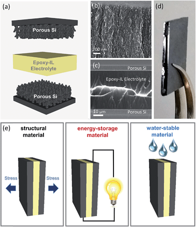
In order to develop a water resistant electrolyte, hydrophobic and commercially obtained bisphenol A/F based Super Sap CCR epoxy resin (Entropy Resins) was mixed with 1-butyl-3-methyl-imidizolium-tetrafluoroborate (BMIBF4) and lithium tetrafluoroborate (LiBF4) and then cured at 40–45 °C overnight. Compared to other IL, BMIBF4 was observed to yield the best isotropic mixtures with the resin, and LiBF4 was mixed into the solution to enable curing at higher IL loadings as demonstrated previously by Shirshova et al.43,44 The Super Sap CCR epoxy resin was chosen as the structural portion of the electrolyte because of its low viscosity in the uncured state, and it's relatively long working time of 3 hours when used with the corresponding CCS slow hardener (polyoxypropylenediamine – Entropy Resins) that is important to achieve full infiltration of the nanoporous charge storage interface. To fabricate the structural supercapacitors, nanoporous Si electrodes were first synthesized via an electrochemical hydrofluoric acid (HF) etch and passivated via a carbonization procedure, after which the epoxy-IL electrolyte was infiltrated into individual nanoporous electrodes, and then sandwiched into a device and allowed to cure (Fig. 1a). Full infiltration of the porous structure, whereas evident from electrochemical measurements, was confirmed using scanning electron microscopy (SEM) (Fig. 1b, c and S1†). Full cross sectional SEM imaging of the device (Fig. 1c) demonstrates an epoxy-IL film approximately 40 μm in thickness bridging the reinforced silicon interface on either side, with a photograph of a typical device in Fig. 1d. This process resulted in a composite epoxy/IL/porous Si composite material capable of functioning as a water resistant structural composite and energy storage material (Fig. 1e).
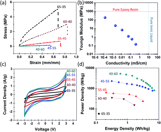
Two preliminary steps critical to this effort are (i) the development of the epoxy-IL electrolyte, and (ii) infiltration of the electrolyte into the nanoporous material to yield a structural supercapacitor. In this manner, tensile stress and ionic conductivity measurements were performed on epoxy-IL electrolytes with compositions ranging from 70% resin and 30% IL to 40% resin and 60% IL. Epoxy-IL electrolytes with greater than 70% resin did not provide measureable ionic conductivities, and ratios with less than 40% resin did not cure properly. We observe the mechanical strength and Young's modulus to decrease exponentially as the IL concentration increases (Fig. 2a and S2†) whereas the ionic conductivity increased exponentially (Fig. S3†). This indicates a balance in IL loading and structural integrity that is highlighted in Fig. 2b. Here, the dotted line across the top represents the Young's modulus of a pure Super Sap CCR epoxy resin, and the dashed line along the right represents the ionic conductivity of a pure IL. The ideal structural electrolyte would occur at the intersection of the two lines having the same strength as a pure resin, but maintaining the ionic conductivity of a pure IL. In our experimental system we observe IL loadings greater than 50% all indicate sufficient ionic conductivity (over 0.1 mS cm−1) to provide competitive energy storage characteristics while at the same time maintaining enough structural integrity (tensile strength over 100 kPa) to function as a structural material.
Next, we studied the effect of differing epoxy-IL ratios on the full device performance. Fig. 2c shows cyclic voltammetry (CV) curves of full composite devices with varying epoxy-IL ratios. These CV curves indicate a stable voltage window near 3 V for all epoxy-IL ratios and a linear increase of capacitance with IL loading (Fig. S4a and b†), which is further confirmed with galvanostatic charge–discharge measurements (Fig. S5†), galvanostatic measurements also indicate a linear and exponential increase of energy and power density, respectively, with IL loading (Fig. 2d) attributed to the effect of series resistance on ion concentration (Fig. S4d†). As a result, structural supercapacitors could only be practically developed with 40% or greater IL concentration. This was evidenced by the fact that we could only get a single data point for the Ragone curve in Fig. 2d for the ratio of 65–35, and none for higher epoxy loadings due to instantaneous discharge due to resistance. This leads to devices, with optimal electrolyte configurations, which yield energy density of 5–8 W h kg−1 and power density near 4 kW kg−1. This is on par with activated carbon materials utilized in commercial supercapacitors and at minimum two orders of magnitude better than structural capacitor storage capability exhibited with carbon fiber electrodes.19–21,24 Notably, cycling tests demonstrate the ability to retain almost 100% of the energy density over the course of 4000 cycles (Fig. S6†).
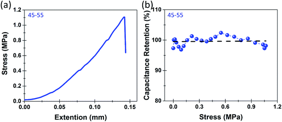
Whereas this represents the operation of the individual components of the device, in order for this to be considered a multifunctional structural energy storage device it must demonstrate mechanical integrity and high quality energy storage simultaneously. This distinguishes our work from other reports, which only consider the separate mechanical and electrochemical performance of structural or multifunctional energy storage systems. To carry this out, we assess in situ mechano–electrochemical performance of the devices using standard tensile tests at slow rates in order to perform in situ electrochemical measurements. Fig. 3a shows the in situ stress strain curve for a nanoporous epoxy/IL/silicon composite with an epoxy-IL ratio of 45–55 by weight. The full device exhibited standard elastic behavior until failure occurred in the electrode's mechanical connections (at the grip/silicon interface) at about 1.1 MPa. At this tensile stress, structural device failure had not yet occurred, emphasizing this result as a lower limit of tensile strength for the structural storage device, which still represents a 3–4× improvement over PEO based devices.31 The greater tensile strength measured for the device versus the long molded bulk epoxy-IL electrolyte sample also represents the difference in geometry on defect mediated bulk failure of the epoxy-IL electrolyte. Following from this result, Fig. 3b indicates that the overall capacitance remains stable, with exception of minor (<3–4%) fluctuations, over the course of the tensile measurement. This emphasizes the signature of a structural energy storage material, with excellent charge storage capability even when subject to mechanical stresses.
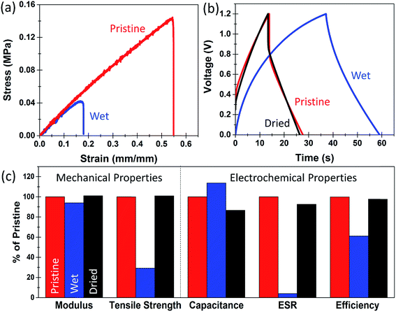
Whereas the basic requirement for a structural energy storage material is the ability to simultaneously maintain mechanical integrity and store and release energy, most structural materials integrated into technological systems are subject to environmental conditions, unless otherwise packaged. In this manner, the prospect of packaging for a composite material that would be integrated into a building or on an electric vehicle or an aircraft would present significant challenges. Therefore, the native function of structural energy storage would need to be maintained in an environment subject to humidity and precipitation. This poses a significant challenge for many conventional polymeric systems when used as ionic conducting polymer electrolytes which are highly unstable in aqueous environments, such as PEO which spontaneously dissolve in water (Fig. S7†). To assess the water stability of our structural energy storage devices, we simulated an extreme condition where the devices or epoxy-IL electrolytes are soaked underwater for 2 hours prior to testing. Fig. 4a shows two tensile tests of 45–55 bulk epoxy-IL electrolytes that were prepared at the same time. One of them was tested after being soaked in water for 2 hours while the other one was tested in its pristine condition (no water exposure) (a picture of the wet and dry electrolytes is found in Fig. S8†). The Young's modulus for the wet sample slightly decreased by 5%, and the ultimate tensile strength was reduced by about 65%. However, we observe this effect to be completely reversible upon drying (Fig. 4c and S9†). As the epoxy-IL electrolytes visually indicate a slight effect of physical swelling, we attribute this change to water absorption which is fully reversible after drying occurs. This is in direct contrast to a PEO electrolyte with a similar PEO![[thin space (1/6-em)]](https://www.rsc.org/images/entities/char_2009.gif) :
:![[thin space (1/6-em)]](https://www.rsc.org/images/entities/char_2009.gif) EMIBF4 ratio (50
EMIBF4 ratio (50![[thin space (1/6-em)]](https://www.rsc.org/images/entities/char_2009.gif) :
:![[thin space (1/6-em)]](https://www.rsc.org/images/entities/char_2009.gif) 50) where the mechanical integrity was compromised within 1 minute of being immersed in water and complete dissolution occurred within 30 minutes – shorter than the timeframe of water exposure in our epoxy-IL electrolyte tests (Fig. S6†).
50) where the mechanical integrity was compromised within 1 minute of being immersed in water and complete dissolution occurred within 30 minutes – shorter than the timeframe of water exposure in our epoxy-IL electrolyte tests (Fig. S6†).
In addition to wet–dry testing of epoxy-IL electrolytes, we further performed a similar two hour soak test on a full structural supercapacitor device to ascertain the effect of water immersion on the electrochemical performance. The device was first tested in an as-prepared state, immersed in water and tested in this condition, and then tested again after drying. Fig. 4b shows representative galvanostatic charge discharge measurements taken in these different conditions. While immersed in water for 2 hours the device exhibited a significantly lower equivalent series resistance, and a corresponding significant increase in the specific capacitance (Fig. 4c and S10†). It also exhibited a significant decrease in the coulombic efficiency from 99% to 60% while immersed underwater likely due to a portion of faradaic localized water splitting or electrochemical oxidation. After drying, the device performance recovered very close to its initial pristine condition but with a small decrease in the specific capacitance, which could represent oxidation effects in either the resin or electrodes. Despite the small decrease in capacitance after an extreme condition of water exposure, the device performance is maintained for both charge storage and mechanical integrity during and after immersion. Therefore, under exposure to less extreme environments such as high humidity or periods of rain that are more likely in working environments, the inherent function of the multifunctional structural energy storage material would remain in-tact.
Conclusions
Overall, we demonstrate the first structural supercapacitor capable of simultaneously storing and releasing energy under tensile stresses of greater than 1 MPa and under extreme conditions of water immersion. This is enabled through the development of a bisphenol A/F epoxy-IL electrolyte exhibiting passive behavior in humid or aqueous environments, but with curing characteristics enabling epoxy-IL infiltration into a high surface nanoporous reinforcing interface. We measure energy densities of up to 5–8 W h kg−1 with nearly 100% energy retention over 4000 cycles and at tensile stresses over 1 MPa. We further observe any temporary adverse effect of extreme water exposure on these devices to be reversible, motivating their use for long-term energy carriers without the need for additional packaging to achieve stable operation in outdoor environments. This work lays the foundation for an emerging class of energy storage materials that can both catalyze technological progress and foster new applications requiring built-in energy delivery capability.Acknowledgements
We thank K. Share, A. Cohn, and R. Carter for useful discussions related to this work. This work was supported in part by NSF grant CMMI 1334269, NASA EPSCoR grant NNX13AB26A, and an ORAU Ralph E. Powe award.References
- J. S. Lee, S. Tai Kim, R. Cao, N. S. Choi, M. Liu, K. T. Lee and J. Cho, Adv. Energy Mater., 2011, 1, 34–50 CrossRef CAS PubMed.
- M. A. Rahman, X. Wang and C. Wen, J. Appl. Electrochem., 2014, 44, 5–22 CrossRef CAS.
- A. S. Aricò, P. Bruce, B. Scrosati, J.-M. Tarascon and W. van Schalkwijk, Nat. Mater., 2005, 4, 366–377 CrossRef PubMed.
- S. Evers and L. F. Nazar, Acc. Chem. Res., 2012, 46, 1135–1143 CrossRef PubMed.
- X.-P. Gao and H.-X. Yang, Energy Environ. Sci., 2010, 3, 174–189 CAS.
- B. Dunn, H. Kamath and J.-M. Tarascon, Science, 2011, 334, 928–935 CrossRef CAS PubMed.
- B. Kang and G. Ceder, Nature, 2009, 458, 190–193 CrossRef CAS PubMed.
- P. Simon and Y. Gogotsi, Nat. Mater., 2008, 7, 845–854 CrossRef CAS PubMed.
- A. S. Westover, D. Freudiger, Z. S. Gani, K. Share, L. Oakes, R. E. Carter and C. L. Pint, Nanoscale, 2015, 7, 98–103 RSC.
- S. W. Kim, D. H. Seo, X. Ma, G. Ceder and K. Kang, Adv. Energy Mater., 2012, 2, 710–721 CrossRef CAS PubMed.
- A. Z. Weber, M. M. Mench, J. P. Meyers, P. N. Ross, J. T. Gostick and Q. Liu, J. Appl. Electrochem., 2011, 41, 1137–1164 CrossRef CAS.
- M. D. Slater, D. Kim, E. Lee and C. S. Johnson, Adv. Funct. Mater., 2013, 23, 947–958 CrossRef CAS PubMed.
- A. S. Westover, K. Share, R. Carter, A. P. Cohn, L. Oakes and C. L. Pint, Appl. Phys. Lett., 2014, 104, 213905 CrossRef PubMed.
- T. Chen, Z. Yang and H. Peng, ChemPhysChem, 2013, 14, 1777–1782 CrossRef CAS PubMed.
- W. Guo, X. Xue, S. Wang, C. Lin and Z. L. Wang, Nano Lett., 2012, 12, 2520–2523 CrossRef CAS PubMed.
- J. F. Snyder, E. L. Wong and C. W. Hubbard, J. Electrochem. Soc., 2009, 156, A215–A224 CrossRef CAS PubMed.
- D. O'Brien, D. Baechle and E. Wetzel, J. Compos. Mater., 2011, 45, 2797–2809 CrossRef PubMed.
- T. Pereira, Z. Guo, S. Nieh, J. Arias and H. T. Hahn, J. Compos. Mater., 2009, 43, 549–560 CrossRef CAS PubMed.
- Y. Huang, H. Hu, Y. Huang, M. Zhu, W. Meng, C. Liu, Z. Pei, C. Hao, Z. Wang and C. Zhi, ACS Nano, 2015, 9, 6242–6251 CrossRef CAS PubMed.
- Y. Huang, Y. Huang, W. Meng, M. Zhu, H. Xue, C.-S. Lee and C. Zhi, ACS Appl. Mater. Interfaces, 2015, 7, 2569–2574 CAS.
- Y. Huang, Y. Huang, M. Zhu, W. Meng, Z. Pei, C. Liu, H. Hu and C. Zhi, ACS Nano, 2015, 9, 6242–6251 CrossRef CAS PubMed.
- N. Shirshova, H. Qian, M. S. Shaffer, J. H. Steinke, E. S. Greenhalgh, P. T. Curtis, A. Kucernak and A. Bismarck, Composites, Part A, 2013, 46, 96–107 CrossRef CAS PubMed.
- H. Qian, A. R. Kucernak, E. S. Greenhalgh, A. Bismarck and M. S. Shaffer, ACS Appl. Mater. Interfaces, 2013, 5, 6113–6122 CAS.
- H. Qian, H. Diao, N. Shirshova, E. S. Greenhalgh, J. G. Steinke, M. S. Shaffer and A. Bismarck, J. Colloid Interface Sci., 2013, 395, 241–248 CrossRef CAS PubMed.
- A. Javaid, K. Ho, A. Bismarck, M. Shaffer, J. Steinke and E. Greenhalgh, J. Compos. Mater., 2014, 48, 1409–1416 CrossRef CAS PubMed.
- Y. Lin and H. A. Sodano, J. Appl. Phys., 2009, 106, 114108 CrossRef PubMed.
- N. Shirshova, H. Qian, M. Houllé, J. H. Steinke, A. R. Kucernak, Q. P. Fontana, E. S. Greenhalgh, A. Bismarck and M. S. Shaffer, Faraday Discuss., 2014, 172, 81–103 CAS.
- A. S. Westover, J. W. Tian, S. Bernath, L. Oakes, R. Edwards, F. N. Shabab, S. Chatterjee, A. V. Anilkumar and C. L. Pint, Nano Lett., 2014, 14, 3197–3202 CrossRef CAS PubMed.
- J. Benson, I. Kovalenko, S. Boukhalfa, D. Lashmore, M. Sanghadasa and G. Yushin, Adv. Mater., 2013, 25, 6625–6632 CrossRef CAS PubMed.
- R. Agrawal and G. Pandey, J. Phys. D: Appl. Phys., 2008, 41, 223001 CrossRef.
- D. T. Hallinan Jr and N. P. Balsara, Annu. Rev. Mater. Res., 2013, 43, 503–525 CrossRef.
- D. Mecerreyes, Prog. Polym. Sci., 2011, 36, 1629–1648 CrossRef CAS PubMed.
- Z. S. Wu, A. Winter, L. Chen, Y. Sun, A. Turchanin, X. Feng and K. Müllen, Adv. Mater., 2012, 24, 5130–5135 CrossRef CAS PubMed.
- A. S. Westover, F. N. Shabab, J. W. Tian, S. Bernath, L. Oakes, W. R. Erwin, R. Carter, R. Bardhan and C. L. Pint, J. Electrochem. Soc., 2014, 161, E112–E117 CrossRef CAS PubMed.
- C. Tang, K. Hackenberg, Q. Fu, P. M. Ajayan and H. Ardebili, Nano Lett., 2012, 12, 1152–1156 CrossRef CAS PubMed.
- A. M. Stephan, Eur. Polym. J., 2006, 42, 21–42 CrossRef PubMed.
- N. Srivastava and T. Tiwari, e-Polym., 2009, 9, 1738–1754 Search PubMed.
- K. Devanand and J. Selser, Nature, 1990, 343, 739–741 CrossRef CAS PubMed.
- L. Maggi, L. Segale, M. Torre, E. O. Machiste and U. Conte, Biomaterials, 2002, 23, 1113–1119 CrossRef CAS.
- E. M. van Wagner, A. C. Sagle, M. M. Sharma, Y.-H. La and B. D. Freeman, J. Membr. Sci., 2011, 367, 273–287 CrossRef CAS PubMed.
- S. Chatterjee, R. Carter, L. Oakes, W. R. Erwin, R. Bardhan and C. L. Pint, J. Phys. Chem. C, 2014, 118, 10893–10902 CAS.
- L. Oakes, A. Westover, J. W. Mares, S. Chatterjee, W. R. Erwin, R. Bardhan, S. M. Weiss and C. L. Pint, Sci. Rep., 2013, 3, 3020 Search PubMed.
- N. Shirshova, A. Bismarck, S. Carreyette, Q. P. Fontana, E. S. Greenhalgh, P. Jacobsson, P. Johansson, M. J. Marczewski, G. Kalinka and A. R. Kucernak, J. Mater. Chem. A, 2013, 1, 15300–15309 CAS.
- N. Shirshova, A. Bismarck, E. S. Greenhalgh, P. Johansson, G. Kalinka, M. J. Marczewski, M. S. Shaffer and M. Wienrich, J. Phys. Chem. C, 2014, 118, 28377–28387 CAS.
Footnote |
| † Electronic supplementary information (ESI) available. See DOI: 10.1039/c5ta05922d |
| This journal is © The Royal Society of Chemistry 2015 |


