
 Open Access Article
 This Open Access Article is licensed under a
 Creative Commons Attribution 3.0 Unported Licence
Highly conducting reduced graphene synthesis via low temperature chemically assisted exfoliation and energy storage application†
Chanderpratap
Singh
a,
Ashish Kumar
Mishra
*b and
Amit
Paul
*a
aDepartment of Chemistry, Indian Institute of Science Education and Research (IISER) Bhopal, Madhya Pradesh, India 462066. E-mail: apaul@iiserb.ac.in
bDepartment of Physics, Indian Institute of Science Education and Research (IISER) Bhopal, Madhya Pradesh, India 462066. E-mail: akmishra@iiserb.ac.in
First published on 3rd August 2015
Abstract
We report a facile approach towards mass production of few layered reduced graphene by low-temperature (160 °C) exfoliation of graphite oxide under ambient atmospheric conditions with the aid of formic acid in a short duration (∼14 min). The obtained reduced graphene showed very high bulk electrical conductivity (1.6 × 10³ S cm−1) at room temperature due to restoration of extended conjugation of the sp2 network during rapid exfoliation. Protonation followed by the hydride transfer mechanism has been proposed for the restoration of extended conjugation and high electrical conductivity. BET surface areas of 789 and 1130 m2 g−1 with narrow mesopore distribution (1.9–2.5 nm) were obtained for two different samples prepared by modification in the synthetic methodology. The reduced graphenes were tested as supercapacitors and specific capacitances of 152 and 157 F g−1 with excellent cyclic stability were observed for two samples in aqueous electrolytes.
Introduction
Graphene is a two-dimensional single atom thick high surface area material which exhibits excellent electrical, mechanical, and thermal properties having many potential applications in the fields of electronics, optoelectronics, and energy devices. The high intrinsic mobility (2 × 105 cm2 V−1 s−1), good thermal conductivity (5000 W m−1 K−1) and excellent electrical conductivity (106 S cm−1) of graphene that facilitate electron or hole transfer along its two-dimensional surfaces have triggered its extensive investigation in the fields of electronics and thermal energy management. The high theoretical surface area (2630 m2 g−1) and mesoporous structure of graphene makes it a promising electrode material for energy applications such as fuel cells, rechargeable batteries and supercapacitors.1–5 Supercapacitors, also called electrochemical double layer or ultracapacitors, provide a huge amount of energy in a short period of time, which makes them suitable for surge power delivery. Different synthesis methods such as mechanical exfoliation, chemical vapour deposition, chemical reduction and exfoliation have been investigated for the production of high quality graphene.5 As per large scale synthetic requirement for energy applications, chemical exfoliation6 methods are exclusively used but they produced few layered graphene having low electrical conductivities and surface areas with several defects compared to those produced by other methods.4 Cheng and co-workers achieved reduced graphene (RG) with a high electrical conductivity of 2 × 10³ S cm−1 by hydrogen arc discharge exfoliation7 of graphite oxide (GO) at high temperature (1050 °C), a synthetic methodology of high cost.8,9 Researchers also reported low temperature exfoliation of GO with the aid of chemicals like HCOOH,10 HCl,11 and H2SO4,12 but the produced RG suffered from low electrical conductivity. The above discussion indicates that modulation of chemical and thermal exfoliation may lead to large scale production of superior quality graphene.Herein, we report an example of a chemically assisted low-temperature exfoliation route for mass production of graphene. In this work, judiciously formic acid has been chosen, which governs exfoliation of GO at low temperature (160 °C) within a short duration of 14 min with sudden eruption. The produced graphene exhibits excellent bulk electrical conductivity (1.6 × 10³ S cm−1), high surface area (1130 m2 g−1), and good electrochemical energy storage capacity (∼157 F g−1). Moreover, we propose plausible mechanisms based on fundamental organic chemistry reactions for excellent electrical conductivity of RG and also suggest the usage of as-prepared RG as the electrode material for supercapacitors. This approach will lead to new facile ways for the mass production of quality graphene under ambient conditions which can be used as energy devices.
Experimental section
Materials and methods
Graphite (particle size: 150 micron, Cat# 496588), concentrated sulfuric acid (Cat# 320501), formic acid (Cat# F0507), sodium nitrate, N-methyl-2-pyrrolidone (NMP), poly(vinylidene fluoride) (PVDF), potassium bromide and barium chloride solution were purchased from Sigma-Aldrich. Platinum (Pt) foil and Pt wire were purchased from Alfa Aesar. A standard calomel electrode (SCE) was purchased from CH Instruments, TX, USA. Hydrogen peroxide (30%) was purchased from Rankem, India. Potassium permanganate was purchased from Fischer Scientific. Acetone was purchased from Spectrochem, India. Milli-Q water (>18 MΩ cm) was used in all the synthesis processes.Synthesis of RG
GO was prepared using a Hummers' method.13 Graphite (particle size: 150 micron) (2.5 g) was first sonicated in acetone for 30 minutes. Thereafter, it was filtered through a sintered glass filter and dried in an oven at 45 °C for 2 h. It (2 g) was suspended in 46 mL concentrated sulfuric acid in an ice bath (0 °C) in a 250 mL round bottom flask equipped with a magnetic stir bar. Separately, synthesis was also performed by suspending graphite (2 g) and NaNO3 (1 g) in concentrated sulfuric acid for GO synthesis. 6 g of KMnO4 was then added cautiously covering a time span of approximately 20 min so that the temperature of the solution did not exceed 20 °C. The solution was then stirred at 35 °C using a reflux condenser for 3 h. After that, 92 mL of distilled water was added and stirring continuously for an additional period of 30 min. Then the content was poured into 280 mL of distilled water and 10 mL of 30% hydrogen peroxide was added to destroy the excess KMnO4. The complete removal of KMnO4 was indicated by a color change from dark to yellow. GO was then isolated by using a sintered glass filter and washed with copious amounts of water (500 mL). Washing was continued until sulphate was no longer detected in the filtrate which was confirmed by addition of barium chloride solution to the filtrate. Thereafter, the filtrate was washed with formic acid solution (20%) to intercalate formic acid in the inter-lamellar region of GO and dried in an oven at 60 °C for 24 h. Prepared GOs were named GO (150) and GO (150 + N) (NaNO3 was used during synthesis). The numeric 150 indicates the particle size of the parent graphite precursor purchased from Sigma-Aldrich. After drying, GO samples were stored in vials under ambient conditions. The bold sentence indicates the synthetic modification of this study from our previous study.14 For GO reduction, 0.5 g of prepared GOs were poured in a 500 mL conical flask. Thereafter the conical flask was kept inside the preheated hot air oven at 160 °C for 14 min to complete the exfoliation process. One of the aims of this work was to perform the exfoliation process at a lowest possible temperature to make the graphene synthesis cost effective. By performing several experiments, it has been found that 160 °C is the minimum temperature required for exfoliation to achieve high quality graphene. Digital images were taken before and after exfoliation and are shown in the ESI (Fig. S1†). Two different reduced graphene (RG) materials were named RG (150) and RG (150 + N).Characterization
The powder X-ray diffraction (PXRD) patterns were recorded by using a Bruker AXS D8 Advance with Cu Kα radiation (1.54 Å) with a step size of 0.02° in a 2θ range of 0–60°. Thermal gravimetric analysis (TGA) was performed by using a Perkin-Elmer TGA 4000 instrument in a temperature range from 30 to 900 °C at a scan rate of 5 °C min−1 with a N2 flow rate of 10 mL min−1. For morphological studies, dried samples were spread over carbon tape and gold coated for 120 s, and scanning electron microscopy (SEM) studies were performed using a Carl ZEISS (ultraplus) FE-SEM at 20 kV. Energy dispersive X-ray (EDS) experiments were performed at a working voltage of 20 kV and was standardized with the Co element by using a spectrometer (Oxford Instruments X-MaxN) attached to the SEM. Transmission electron microscopy (TEM, JEOL 2100F) experiments were performed under an accelerating voltage of 200 kV. TEM samples were prepared by drop casting the suspension of the sample (0.5 mg in 15 mL isopropanol) onto a carbon-coated copper grid and the solvent was evaporated under ambient conditions overnight. The Raman spectroscopy experiments were performed by using a Lab RAM HR 800 (HORIBA) with an excitation wavelength of 632.8 nm. Nitrogen adsorption/desorption experiments were performed on Quantachrome Autosorb QUA211011 equipment for surface area measurements. The samples were degassed under high vacuum at 100 °C for 24 h. FT-IR spectra were collected using a Perkin-Elmer spectrum BX spectrophotometer using the pellets of samples with KBr. Electrical conductivity measurements were carried out on a physical property measurement system (PPMS, Model 6000) Quantum Design, USA. Electrochemical experiments were carried out using a CH Instruments, Austin, TX bipotentiostat (Model CHI 760D) and potentiostat (Model CHI 620E). Capacitance measurements were performed using cyclic voltammetry, galvanostatic charge/discharge and electrochemical impedance spectroscopy (EIS) techniques with a regular three electrode cell. Electrode preparation details and capacitance calculation methodologies are discussed in the ESI.† The elemental analysis experiment was carried out on an Elementar Analysen systeme Gnbh, Germany. The samples were dried at 60 °C for 12 h before performing the experiment.Results and discussion
RGs were synthesized by reducing GO at low temperature (160 °C) with the chemical aid of formic acid as described in the Experimental section. Graphite oxide (GO) contains oxygen functionalities such as epoxy, hydroxyl, and carboxyl. Due to the presence of these functional groups, GO decomposes to produce gases such as CO2 and H2O during thermal treatment at low temperatures, but cannot generate enough pressure to overcome van der Waals forces at low temperatures. In order to make the exfoliation process efficacious, the pressure generated from evolved gases should surpass the van der Waals forces holding GO sheets which can be achieved by external chemical aids. We accomplished this process by introducing formic acid (HCOOH) as a hydride donor15 and a volatile substance into the inter-lamellar region of GO during the filtration process. The reducing nature of formic acid can be understood by its propensity to lose both hydrogen and generate CO2.15 During the heating process, CO2 was released from formic acid after hydride donation to electrophilic centers and supplied extra pressure to accelerate the expansion of GO, leading to fast exfoliation under ambient conditions (schematically represented in Fig. 1 and digital images of the reaction are shown in Fig. S1 of the ESI†). The detailed mechanistic understanding of the synthetic methodology has been discussed as well (vide infra). | ||
| Fig. 1 Schematic representation of chemically assisted low temperature exfoliation of GO with the aid of formic acid. | ||
The exfoliation of GO was first confirmed by powder X-ray diffraction (PXRD) and is shown in Fig. 2. The observed shift in 2θ maxima for the (002) plane from 10.8° (GO) to 23.4° (RG) corresponds to interlayer distances of 0.82 nm and 0.38 nm, respectively. Peak broadening of RGs compared to GOs indicates decreases in crystallite lengths along the c-axis (Lc) i.e. decrease in the number of layers.14 Synthesized RGs had around 5 layers of graphene sheets, calculated using Scherrer's formula and the Voigt function16 for peak fitting, as given in the ESI.† As an example, utilizing a low temperature chemically assisted exfoliation method, Zheng and co-workers obtained 5–6 layers of graphene sheets.11 Weak peaks were also observed around a 2θ maximum of 42.5° for the (100) plane which were fitted using the Voigt function and crystallite lengths along the a-axis (La) were calculated using Scherrer's formula. La values of RGs were found to be ∼7.5 nm. Table 1 shows the decrease in crystallite length (25 times decrease along the c-axis i.e. Lc and 11 times decrease along the a-axis i.e. La) for reduced graphenes compared to the parent graphite.
 | ||
| Fig. 2 PXRD patterns for pristine graphite, GO (150) and RG (150) (a) and graphite, GO (150 + N) and RG (150 + N) (b). | ||
| Sample code | 2θ maxima (°) | (FWHM)Lc (°) | L c (nm) | d (Å) | Number of layers | (FWHM)La (°) | L a (nm) |
|---|---|---|---|---|---|---|---|
| Graphite (150 μm) | 26.4 | 0.19 | 43 | 3.4 | 127 | 0.19 | 89 |
| GO (150) | 10.8 | 0.96 | 8.6 | 8.2 | 11 | 0.60 | 27 |
| GO (150 + N) | 10.8 | 0.98 | 8.1 | 8.2 | 10 | 0.66 | 25 |
| RG (150) | 23.4 | 4.62 | 1.7 | 3.8 | 5 | 2.32 | 7.0 |
| RG (150 + N) | 23.4 | 4.53 | 1.8 | 3.8 | 5 | 2.01 | 8.1 |
Layered structures of RGs were confirmed using scanning and transmission electron microscopy (SEM & TEM) techniques. Fig. 3a and e show the SEM images of RG (150) and RG (150 + N) samples, respectively, depicting few layered structures of RGs after rapid exfoliation. RG (150) shows more separated layers compared to those for RG (150 + N). TEM images (Fig. 3b and f) indicate entangled few layer sheets for RG (150) and RG (150 + N), respectively. High resolution TEM images (Fig. 3c and g) indicate 3–5 layer distribution in each stack of RG samples. Fig. 3d and h show the selected area electron diffraction (SAED) pattern for RG samples. The SAED pattern for RG (150) indicates well-defined diffraction spots corresponding to the hexagonal structure of planar graphene sheets, while RG (150 + N) shows a diffused circular ring due to different orientation and large distribution of layers.8 It reveals that the degree of exfoliation was more controlled in RG (150) compared to RG (150 + N) leading to retention of the hexagonal symmetry in RG (150). Furthermore, qualities of synthesized RGs were evaluated by TGA and the results are shown in the ESI (Fig. S2†). RG (150) and RG (150 + N) showed a weight loss of 8 and 11%, respectively up to 250 °C, which can be attributed to the loss of water and labile oxygen functionalities. Furthermore, 7.5 and 11% weight losses were observed for RG (150) and RG (150 + N), respectively, in the temperature range 250–510 °C, which can be attributed to the loss of residual functional groups. The higher weight loss for RG (150 + N) indicates the presence of more functional groups in RG (150 + N). In a previous report by our group,14 we concluded that the addition of NaNO3 during GO synthesis favors strong basal plane oxidation on graphene sheets which generates more functional groups on basal planes and hence slightly more functional groups may remain in graphene sheets for RG (150 + N) compared to RG (150). This conclusion can be further supported by the lower conductivity of RG (150 + N) compared to RG (150) (vide infra).
 | ||
| Fig. 3 SEM images of graphene sheets (a and e). TEM images of graphene sheets (b and f). HRTEM images showing the number of layers stacked (c and g). SAED contains information about crystallinity for RG (150) and RG (150 + N) (d and h) respectively. | ||
As a strong tool to characterize sp2 carbon domains, Raman spectroscopy was performed for synthesized RG samples and the spectra are shown in the ESI (Fig. S3†). RGs exhibit a D band around 1330 and a G band around 1589 cm−1. The D band corresponds to disorder while the G band indicates the in-plane vibrations of carbon atoms. A large shift in the G band of RGs compared to parent graphite was observed, indicating few layered structures of RGs.17 The intensity ratio of D band to G band (ID/IG) directly measures the degree of disorder.18 Decreased ID/IG ratios for RGs compared to those of GOs indicate the reduced disorder due to thermal exfoliation as described by Kudin and co-workers.19
BET adsorption/desorption profiles for N2 are shown in Fig. 4a which exhibit characteristics of type-III and IV isotherms with a hysteresis loop of H2 type (according to IUPAC classification) in the range (0.45–1.0) for P/P0, implying the mesoporous nature of synthesized RGs. BET surface areas of 789 and 1130 m2 g−1 with pore volumes of 5.5 and 11.84 cm3 g−1 were observed for RG (150) and RG (150 + N), respectively. RGs showed narrow pore size distribution in the range of 1.9–2.5 nm, calculated using the Barrett–Joyner–Halenda (BJH) method.20 For comparison, Zheng and co-workers11 reported a surface area of 500 m2 g−1 by thermal exfoliation at 130 °C, Aksay and co-workers9 reported 650 m2 g−1 at 1050 °C, and Ruoff and co-workers21 reported a surface area of 705 m2 g−1 for chemically exfoliated graphene sheets. Surface areas for RGs achieved by the present method are higher than those by other thermal and chemical exfoliation methods.
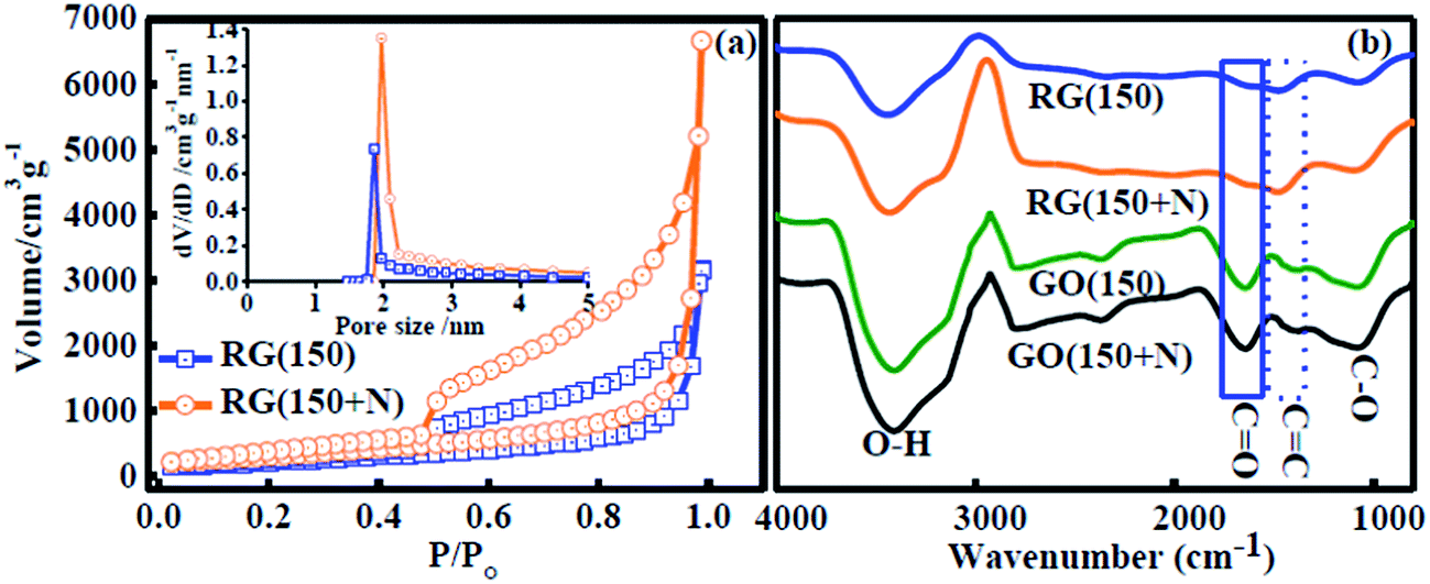 | ||
| Fig. 4 (a) N2 adsorption/desorption isotherm plot and BJH plot (inset) showing very narrow pore distribution (1.9–2.5 nm, pore size of ≤2 nm) for RG (150) and RG (150 + N). (b) FT-IR spectra of GOs and RGs. | ||
FT-IR spectra of GOs and RGs are compared in Fig. 4b. A significant decrease in the intensity of stretching vibrations of C![[double bond, length as m-dash]](https://www.rsc.org/images/entities/char_e001.gif) O (1654 cm−1), C–O (1080 cm−1) and an increase in the stretching vibration of CC (1466 cm−1) were observed from GOs to RGs. These results indicate the reducing nature of formic acid towards selective oxygen functionalities. Restoration of π conjugation in synthesized RGs was evident from electrical conductivity measurements. High bulk electrical conductivities of (1.6 ± 0.09) × 103 and (1.4 ± 0.07) × 103 S cm−1 were observed for RG (150) and RG (150 + N) respectively, measured by a four probe method. Bulk electrical conductivity achieved in the present work is found to be superior to most of the reports as summarized in Table 2. The excellent electrical conductivity of synthesized RGs can be attributed to the significant decrease in the CO stretching (Fig. 4b), as described in other reports.7,22
O (1654 cm−1), C–O (1080 cm−1) and an increase in the stretching vibration of CC (1466 cm−1) were observed from GOs to RGs. These results indicate the reducing nature of formic acid towards selective oxygen functionalities. Restoration of π conjugation in synthesized RGs was evident from electrical conductivity measurements. High bulk electrical conductivities of (1.6 ± 0.09) × 103 and (1.4 ± 0.07) × 103 S cm−1 were observed for RG (150) and RG (150 + N) respectively, measured by a four probe method. Bulk electrical conductivity achieved in the present work is found to be superior to most of the reports as summarized in Table 2. The excellent electrical conductivity of synthesized RGs can be attributed to the significant decrease in the CO stretching (Fig. 4b), as described in other reports.7,22
| Sample | Preparation method | Electrical conductivity (S cm−1) | Reference |
|---|---|---|---|
| Reduced graphene | Hydrogen arc discharge at 1050 °C | 2 × 10³ | 7 |
| Reduced graphene | Hydrazine reduction at 100 °C | 2 | 6 |
| Reduced graphene | H2SO4 assisted exfoliation at 120 °C | 17 | 12 |
| Reduced graphene | HCl assisted exfoliation at 130 °C | 12 | 11 |
| Reduced graphene | Formic acid reduction at 160 °C | 1.6 × 10 3 | Present study |
The plausible mechanisms for chemically assisted thermal exfoliation are shown in Scheme 1. Basal planes of graphene sheets in GOs contain functional groups such as hydroxyl and epoxy attached with sp3 hybridized carbons and sheet edges contains the carbonyl functionality attached with sp2 hybridized carbons. Protonation followed by hydride (H−) transfer from formic acid (HCOOH) and thereafter release of gases such as H2, CO2 and H2O will lead to removal of these functional groups from graphene sheets.15,23 Released gases created extra pressure for the expansion of graphene sheets at low temperature. The most important feature of formic acid assisted exfoliation is that not only the functional groups were removed but also the driving forces for these reactions were to change the hybridization of carbon atoms from sp3 to sp2 for restoration of π networks. Hence, the mechanism also explains the superior conductivity of RGs.
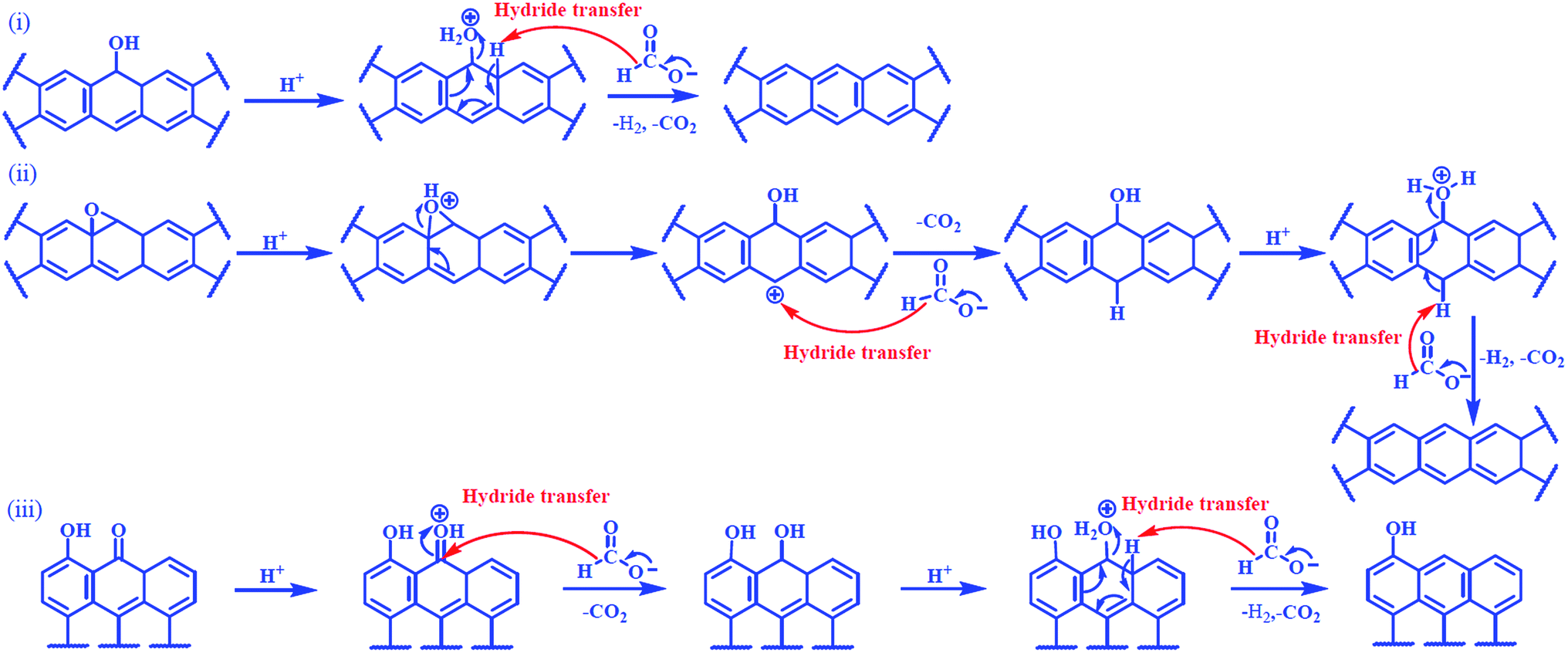 | ||
| Scheme 1 Mechanisms for the reactions between different functionalities of GO and formic acid. (i) Hydroxyl, (ii) epoxy, and (iii) carbonyl. | ||
Inspired by these observations, electrochemical experiments were performed to test these RGs as electrochemical supercapacitors using a regular three electrode cell by depositing the materials on a platinum (Pt) electrode with poly(vinylidene fluoride) binder in 2 M H2SO4 as electrolyte. Nearly rectangular cyclic voltammograms (CV) were obtained (Fig. 5a) even at a faster scan rate of 100 mV s−1 indicating quality charge propagation.21 The CVs at slower scan rates are shown in the ESI (Fig. S6†). Specific capacitances of 157 and 152 F g−1 were observed for RG (150) and RG (150 + N), respectively at a voltage sweep rate of 5 mV s−1. Retention of nearly 86 and 78% for specific capacitances of RG (150) and RG (150 + N), respectively, were observed at a high voltage scan rate of 100 mV s−1 (Fig. 5b). The drop in specific capacitances with increasing scan rate can be attributed to the pseudocapacitance (redox) contribution from the remaining oxygen functionality. These redox contributions in RGs arise due to the presence of hydroxyl functionalities on the sheet edges of graphene sheets24,25 and according to Scheme 1, formic acid cannot remove these functionalities from graphene sheets. TGA results suggest that the functionalities present in RG (150 + N) were higher than those in RG (150) but the electrochemical results show that the redox contribution for RG (150) was higher than that for RG (150 + N). Apparently, these results may seem to contradict with each other but can be understood utilizing the observations of our previous studies14 where we reported that GO synthesis in the absence of NaNO3 results in higher sheet edge oxidation whereas the presence of NaNO3 during GO synthesis results in higher basal plane oxidation on graphene sheets. Hence, RG (150) may have more hydroxyl functionalities on the edges of graphene sheets compared to RG (150 + N) which is responsible for the enhanced redox response of RG (150). It is also important to mention that specific capacitances of RGs in the present study were comparable or greater than most of the other reports for graphene, as shown in Table 3. The high surface area and good electrical conductivity of as-synthesized RGs result in good capacitance performance.
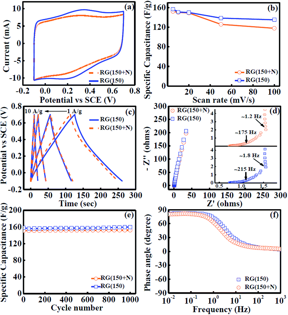 | ||
| Fig. 5 (a) Overlap plot of CVs at a scan rate of 100 mV s−1. (b) Variation of specific capacitances at different scan rates of 100, 50, 20, 10 and 5 mV s−1 in cyclic voltammetry. (c) Galvanostatic charge/discharge measurements at current densities of 1, 2, 5, and 10 A g−1 from right to left respectively. (d) EIS collected at 0 V versus standard calomel electrode (SCE) with the inset showing a zoomed view of a high frequency region with mass transfer frequency. (e) Cyclic stability performance at a scan rate of 20 mV s−1 of cyclic voltammetry. (f) Phase angle versus frequency in the EIS experiment. | ||
| Sample | Preparation method | Specific capacitance (F g−1) | References |
|---|---|---|---|
| Reduced graphene | Hydrazine reduction (100 °C) | 101 F g−1 at 20 mV s−1 | 21 |
| Reduced graphene | Thermal exfoliation (200 °C) in H2 | 80 F g−1 at 10 mV s−1 | 29 |
| Reduced graphene | Thermal exfoliation (1050 °C) | 117 F g−1 at 5 mV s−1 | 30 |
| Reduced graphene | Thermal exfoliation (1000 °C) | 150 F g−1 at 5 mV s−1 | 31 |
| Reduced graphene | Formic acid reduction (160 °C) | 157 F g −1 at 5 mV s −1 | Present work |
The specific capacitances of RGs were also calculated using galvanostatic charge/discharge measurements (Fig. 5c). Calculated specific capacitances with both methods indicate strong agreement between two electrochemical techniques (Table 4). Nyquist plots were analyzed to understand the rate of mass transfer in RGs (Fig. 5d). In the case of RG (150), diffusion of the electrolyte started at 215 Hz corresponding to 0.9 Ω resistance and completed at 1.8 Hz corresponding to 1.5 Ω resistance and thereafter complete capacitor behavior was achieved.26 In the case of RG (150 + N) diffusion of the electrolyte started at 175 Hz corresponding to 0.9 Ω resistance and completed at 1.2 Hz corresponding to 1.7 Ω resistance and thereafter capacitor behavior was completely achieved. These results indicate excellent mass transfer inside the RGs. The excellent mass transport can be explained by the narrow mesopore distribution in the range (1.9–2.5 nm) (vide supra) in RGs which could decrease the ion-diffusion length, hence minimizing inner-pore resistance and also providing large accessible surface area for ion transport/charge storage.27,28 The cyclic performance (Fig. 5e) indicates nearly 100% stability for both the samples after 1000 cycles, indicating the robustness of the material and excellent ion accessibility in the graphene framework during long term cycles.27 The phase angle in the EIS experiment was found to be 83° very close to 90° at low frequencies, indicating the capacitive behaviour of produced RGs (Fig. 5f).
| Scan rate (mV s−1) | RG (150) | RG (150 + N) | Current densities (A g−1) | RG (150) | RG (150 + N) |
|---|---|---|---|---|---|
| 5 | 157 | 152 | 1 | 163 | 157 |
| 10 | 151 | 143 | 2 | 145 | 150 |
| 20 | 151 | 135 | 5 | 134 | 136 |
| 50 | 139 | 126 | 10 | 127 | 123 |
| 100 | 135 | 118 |
The higher capacitance and low cost production of prepared RGs compared to other reports29–31 clearly indicate the suitability of prepared RGs for supercapacitor electrodes. The narrow mesoporous texture of RGs reduces the inner pore resistance and facilitates high mass transfer even at higher frequencies. Additionally, the higher electrical conductivity of RGs can reduce the ohmic loss and cut down the internal resistance for better charge propagation, as observed in the near square shape of CV curves at high scan rates (Fig. 5a).
Conclusions
In conclusion, we have successfully demonstrated an easily operative cost effective synthetic method for bulk production of RGs at low temperature (160 °C) in a time span of only 14 min with the aid of formic acid having excellent physical properties. Less energy consuming and large scale production of mesoporous RGs with high surface area and excellent electrical conductivity enables this study for commercial viability of RGs, having applications in the fields of batteries, catalysis, sensors, and supercapacitors. It is important to mention that in this work, we synthesized two different reduced graphene samples where GOs were synthesized with and without addition of NaNO3. The results presented here show that reduced graphene prepared from GO without the addition of NaNO3 had better properties such as higher conductivity and higher specific capacitance due to the presence of lesser functional groups. Finally, it is worth mentioning that well known fundamental organic chemistry reactions between oxygen functional groups of GO and formic acid were the key behind the success of this work.Acknowledgements
A.P. acknowledges financial support from the Department of Science and Technology (DST), India (Grant no.: SB/FT/CS-165/2012), and IISER Bhopal. A.K.M thanks support of DST, India for Inspire Faculty Award (Grant No: DST/INSPIRE/04/2014/000991). C.S. acknowledges Council for Scientific and Industrial Research (CSIR), India, for providing a fellowship. The authors thank AIRF, JNU and Dr Gajender Saini for help in TEM studies. We sincerely thank Dr Alakesh Bisai, IISER Bhopal, for his valuable suggestions.References
- M. J. Allen, V. C. Tung and R. B. Kaner, Chem. Rev., 2010, 110, 132 CrossRef CAS PubMed.
- A. K. Geim and K. S. Novoselov, Nat. Mater., 2007, 6, 183 CrossRef CAS PubMed.
- C. N. R. Rao, H. S. S. R. Matte and K. S. Subrahmanyam, Acc. Chem. Res., 2013, 46, 149 CrossRef CAS PubMed.
- C. N. R. Rao and A. K. Sood, Graphene: Synthesis, Properties and Phenomena, Wiley-VCH, Weinheim, 2013 Search PubMed.
- Y. Zhu, S. Murali, W. Cai, X. Li, J. W. Suk, J. R. Potts and R. S. Ruoff, Adv. Mater., 2010, 22, 3906 CrossRef CAS PubMed.
- S. Stankovich, D. A. Dikin, R. D. Piner, K. A. Kohlhaas, A. Kleinhammes, Y. Jia, Y. Wu, S. T. Nguyen and R. S. Ruoff, Carbon, 2007, 45, 1558 CrossRef CAS PubMed.
- Z.-S. Wu, W. Ren, L. Gao, J. Zhao, Z. Chen, B. Liu, D. Tang, B. Yu, C. Jiang and H.-M. Cheng, ACS Nano, 2009, 3, 411 CrossRef CAS PubMed.
- M. J. McAllister, J.-L. Li, D. H. Adamson, H. C. Schniepp, A. A. Abdala, J. Liu, M. Herrera-Alonso, D. L. Milius, R. Car, R. K. Prud'homme and I. A. Aksay, Chem. Mater., 2007, 19, 4396 CrossRef CAS.
- H. C. Schniepp, J.-L. Li, M. J. McAllister, H. Sai, M. Herrera-Alonso, D. H. Adamson, R. K. Prud'homme, R. Car, D. A. Saville and I. A. Aksay, J. Phys. Chem. B, 2006, 110, 8535 CrossRef CAS PubMed.
- M. Mitra, K. Chatterjee, K. Kargupta, S. Ganguly and D. Banerjee, Diamond Relat. Mater., 2013, 37, 74 CrossRef CAS PubMed.
- B. Shen, D. Lu, W. Zhai and W. Zheng, J. Mater. Chem. C, 2013, 1, 50 RSC.
- Y. Hong, Z. Wang and X. Jin, Sci. Rep., 2013, 3, 3439 Search PubMed.
- W. S. Hummers and R. E. Offeman, J. Am. Chem. Soc., 1958, 80, 1339 CrossRef CAS.
- D. Roy Chowdhury, C. Singh and A. Paul, RSC Adv., 2014, 4, 15138 RSC.
- H. W. Gibson, Chem. Rev., 1969, 69, 673 CrossRef CAS.
- C. Weidenthaler, Nanoscale, 2011, 3, 792 RSC.
- A. C. Ferrari, Solid State Commun., 2007, 143, 47 CrossRef CAS PubMed.
- A. C. Ferrari, J. C. Meyer, V. Scardaci, C. Casiraghi, M. Lazzeri, F. Mauri, S. Piscanec, D. Jiang, K. S. Novoselov, S. Roth and A. K. Geim, Phys. Rev. Lett., 2006, 97, 187401 CrossRef CAS.
- K. N. Kudin, B. Ozbas, H. C. Schniepp, R. K. Prud'homme, I. A. Aksay and R. Car, Nano Lett., 2008, 8, 36 CrossRef CAS PubMed.
- E. P. Barrett, L. G. Joyner and P. P. Halenda, J. Am. Chem. Soc., 1951, 73, 373 CrossRef CAS.
- M. D. Stoller, S. Park, Y. Zhu, J. An and R. S. Ruoff, Nano Lett., 2008, 8, 3498 CrossRef CAS PubMed.
- X. Li, G. Zhang, X. Bai, X. Sun, X. Wang, E. Wang and H. Dai, Nat. Nanotechnol., 2008, 3, 538 CrossRef CAS PubMed.
- J. March, Advanced Organic Chemistry, Wiley, New York, 1999 Search PubMed.
- C. Singh and A. Paul, J. Phys. Chem. C, 2015, 119, 11382 CAS.
- Y. J. Oh, J. J. Yoo, Y. I. Kim, J. K. Yoon, H. N. Yoon, J.-H. Kim and S. B. Park, Electrochim. Acta, 2014, 116, 118 CrossRef CAS PubMed.
- Y. Zhu, S. Murali, M. D. Stoller, K. J. Ganesh, W. Cai, P. J. Ferreira, A. Pirkle, R. M. Wallace, K. A. Cychosz, M. Thommes, D. Su, E. A. Stach and R. S. Ruoff, Science, 2011, 332, 1537 CrossRef CAS PubMed.
- Z.-S. Wu, Y. Sun, Y.-Z. Tan, S. Yang, X. Feng and K. Müllen, J. Am. Chem. Soc., 2012, 134, 19532 CrossRef CAS PubMed.
- D.-W. Wang, F. Li, M. Liu, G. Q. Lu and H.-M. Cheng, Angew. Chem., Int. Ed., 2008, 47, 373 CrossRef CAS PubMed.
- A. K. Mishra and S. Ramaprabhu, J. Phys. Chem. C, 2011, 115, 14006 CAS.
- K. S. Subrahmanyam, S. R. C. Vivekchand, A. Govindaraj and C. N. R. Rao, J. Mater. Chem., 2008, 18, 1517 RSC.
- X. Du, P. Guo, H. Song and X. Chen, Electrochim. Acta, 2010, 55, 4812 CrossRef CAS PubMed.
Footnote |
| † Electronic supplementary information (ESI) available: Additional experimental details, electrochemical data, TGA results, Raman spectra, EDS, PXRD and elemental analysis. See DOI: 10.1039/c5ta04655f |
| This journal is © The Royal Society of Chemistry 2015 |