 Open Access Article
Creative Commons Attribution 3.0 Unported Licence
A one-step route to solubilised, purified or functionalised single-walled carbon nanotubes†
A. J.
Clancy
 ,
J.
Melbourne
and
M. S. P.
Shaffer
*
London Centre for Nanotechnology, Department of Chemistry, Imperial College London, South Kensington, SW7 2AZ, UK. E-mail: m.shaffer@imperial.ac.uk
First published on 10th July 2015
Abstract
Reductive dissolution is a promising processing route for single walled carbon nanotubes (SWCNTs) that avoids the damage caused by ultrasonication and aggressive oxidation whilst simultaneously allowing access to a wealth of SWCNT functionalisation reactions. Here, reductive dissolution has been simplified to a single one-pot reaction through the use of sodium naphthalide in dimethylacetamide allowing direct synthesis of SWCNT Na+ solutions. Gram quantities of SWCNTs can be dissolved at concentrations over 2 mg mL−1. These reduced SWCNT solutions can easily be functionalised through the addition of alkyl halides; reducing steric bulk of the grafting moiety and increasing polarisability of the leaving group increases the extent of functionalisation. An optimised absolute sodium concentration of 25 mM is shown to be more important than carbon to metal ratio in determining the maximum degree of functionalisation. This novel dissolution system can be modified for use as a non-destructive purification route for raw SWCNT powder by adjusting the degree of charging to dissolve carbonaceous impurities, catalyst particles and defective material, before processing the remaining SWCNTs.
1. Introduction
Since their discovery, single walled carbon nanotubes (SWCNTs) have been of great interest due to their high strength,1 stiffness, surface area, and aspect ratio, along with their interesting optoelectronic2 and thermal properties.3 However, due to their high surface energy4 (0.5 eV nm−1), as-produced SWCNTs form aligned bundles5 which are mechanically6 and electronically7 inferior to individualised nanotubes in most applications. Functionalisation of bundled SWCNTs generally occurs at the exposed exterior surface limiting both the total level and the uniformity of functionalisation. As-synthesised carbon nanotubes also routinely contain impurities both in the form of non-nanotube carbons (amorphous and graphitic carbon, and short defective nanotubes) and residual catalyst particles, often contained within graphitic shells and CNT caps.8–10 For these reasons, the superlative properties of SWCNTs can generally only be exploited after purification, individualisation, and stabilisation of the nanotubes in a solvent.The most common route to dispersing SWCNT bundles uses intense sonication and stabilisation of the resulting suspensions with aqueous surfactant solutions,11 amphiphilic or conjugated polymers,12 DNA,13 or amidic/amidinic solvents such as N-methyl pyrrolidone (NMP).14–16 Sonication is difficult to scale and both damages the SWCNT sp2 framework and reduces aspect ratio;17 although alternative, scalable high shear mechanical force dispersion techniques have recently been applied to carbon nanotubes, damage is still a significant issue.18 In any case, the solution formed through sonication still consists primarily of smaller bundles of nanotubes; although the individualised fraction can be separated by ultracentrifugation, it is a low yield, costly, and time consuming process. Oxidation by refluxing nanotubes in nitric acid (or other oxidising conditions) can purify the sample,19 etching away carbonaceous impurities and dissolving metal contaminants, and introducing potentially useful carboxyl groups;20 however, the resultant nanotubes are heavily damaged in the process with carbons atoms removed from the framework,21 leading to large reductions in mechanical properties.22
An alternative route to SWCNT dissolution involves charging of the nanotubes leading to electrostatic repulsion of the resultant nanotubide anions23 (or nanotubium cations) allowing a spontaneous route to truly individualised solutions of nanotubes without damage to the sp2 carbon framework.24 Addition of SWCNTs to chlorosulfonic acid25 leads to spontaneous dissolution of the nanotubes26 through protonation of the SWCNT sidewalls (which can be deprotonated via addition to water)27 at very high concentration.28 However, chlorosulfonic acid is difficult to handle and is incompatible with many chemical species, limiting the options for organic functionalisation. Reductive charging can be accomplished using methodologies including direct electrochemistry,29 Birch reductions,30 addition of group 1 organometallics, and the use of charged organic electron transfer agents.31 In this latter case, dried SWCNTs are initially exposed to a charging agent, typically a group 1 metal with either liquid ammonia or a solution of an organic single electron transport agent such as naphthalene32,33 or 4,4′-di-tert-butylbiphenyl.33 The nanotubide can then be isolated by removal of the charging agent and solvent, and dissolved in one of a selection of polar aprotic solvents. It is worth noting that although widely used for this step, DMSO is thought to partially quench the nanotubide, methylating the nanotubes34 at high nanotubide charge densities. This approach to chemical reduction is typically a time consuming process, requiring several steps followed by high vacuum and/or elevated temperatures to remove the reduction solvent prior to dissolution in a suitable reaction solvent.
Beyond simple dissolution, the raised Fermi level of reduced SWCNTs can be used to access a host of nanotube functionalisation reactions,35 thought to proceed through a single electron transfer mechanism,35,36 similar to the reaction of sodium naphthalide with alkyl halides; the nanotubide reduces a grafting species R–X, which decomposes to an anionic leaving group X− and the radical R˙ which can graft onto the SWCNT sidewall. Many compounds can be grafted allowing for a versatile array of functionalisation, including organohalides37 and disulfides38 for alkyl/arylation, bromine39 for halogenation, carbon dioxide21 for carboxylation, and epoxides40 and vinyl monomers41 for oligo/polymerisations from the SWCNT sidewall.
There is a need to simplify and improve current SWCNT processing (dissolution, functionalisation, and purification) to accelerate work in the area. Herein, a simple SWCNT reduction system is proposed that can facilitate SWCNT dissolution (Fig. 1) and non-damaging purification; the factors which govern the extent of reductive grafting are examined to elucidate the mechanism and maximise the grafting density for future application.
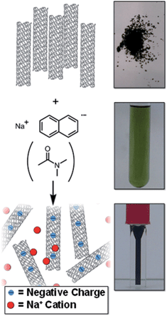 | ||
| Fig. 1 Schematic (left) and pictures (right) of raw SWCNT powder and NaNp solution in DMAc forming a solution of nanotubide. | ||
2. Experimental
2.1. Materials
Elicarb single walled carbon nanotubes (PR929, batch 108511/g), supplied by Thomas Swan Ltd. were dried under vacuum (∼10−2 mbar) at 300 °C for 1 h and 16 h at room temperature before use. All other chemicals were purchased from Sigma Aldrich. Solvents were purchased as anhydrous grade and further dried with activated 4 Å molecular sieves for 2 days prior to use; additionally, THF and DMSO were degassed to completion via freeze–pump–thaw. Sodium (99.95%) was purchased as an ingot; naphthalene (99%) was dried under vacuum in the presence of P2O5. All work was done in a N2 glovebox using oven dried glassware.2.2. Procedures
![[thin space (1/6-em)]](https://www.rsc.org/images/entities/char_2009.gif) :
:![[thin space (1/6-em)]](https://www.rsc.org/images/entities/char_2009.gif) Na ratio of 10
Na ratio of 10![[thin space (1/6-em)]](https://www.rsc.org/images/entities/char_2009.gif) :
:![[thin space (1/6-em)]](https://www.rsc.org/images/entities/char_2009.gif) 1, 19.2 mL of 1 mg(Na) mL−1 sodium naphthalide was diluted with 80.8 mL of DMAc and added to dried SWCNTs (100 mg). The mixture was stirred with a glass stirrer bar overnight before pipetting into fluorinated ethylene propylene (FEP) centrifuge tubes (Oak Ridge) with PTFE tape sealing the cap thread and centrifuged at 10
1, 19.2 mL of 1 mg(Na) mL−1 sodium naphthalide was diluted with 80.8 mL of DMAc and added to dried SWCNTs (100 mg). The mixture was stirred with a glass stirrer bar overnight before pipetting into fluorinated ethylene propylene (FEP) centrifuge tubes (Oak Ridge) with PTFE tape sealing the cap thread and centrifuged at 10![[thin space (1/6-em)]](https://www.rsc.org/images/entities/char_2009.gif) 000g for 30 min; solutions were then pipetted off by hand. Concentrations were measured by quenching 10 mL of solution by bubbling with dry oxygen for ∼20 min before filtering over a tared 100 nm pore PTFE membrane and washing with copious amounts of ethanol, DI water, and acetone, ensuring the sample did not dry out between washings. The sample was then dried at 150 °C for 3 hours and weighed. A membrane subjected to the same washing procedure using 10 mL of DMAc in lieu of the SWCNT solution returned the tared weight (within 0.1 mg).
000g for 30 min; solutions were then pipetted off by hand. Concentrations were measured by quenching 10 mL of solution by bubbling with dry oxygen for ∼20 min before filtering over a tared 100 nm pore PTFE membrane and washing with copious amounts of ethanol, DI water, and acetone, ensuring the sample did not dry out between washings. The sample was then dried at 150 °C for 3 hours and weighed. A membrane subjected to the same washing procedure using 10 mL of DMAc in lieu of the SWCNT solution returned the tared weight (within 0.1 mg).
![[thin space (1/6-em)]](https://www.rsc.org/images/entities/char_2009.gif) 000g for 30 min; supernatant was decanted. Supernatant concentrations were measured as above. Residual purified nanotubes were exposed to a dry oxygen environment overnight and washed by stirring in ethanol, water and acetone, filtering over 100 nm PTFE membranes between steps. It should be noted that some impurities (e.g. residual catalyst particles) may be smaller than the membrane pore size thus the yields should be treated as a lower bound.
000g for 30 min; supernatant was decanted. Supernatant concentrations were measured as above. Residual purified nanotubes were exposed to a dry oxygen environment overnight and washed by stirring in ethanol, water and acetone, filtering over 100 nm PTFE membranes between steps. It should be noted that some impurities (e.g. residual catalyst particles) may be smaller than the membrane pore size thus the yields should be treated as a lower bound.
2.3. Measurements
UV-Vis spectra were taken with a Perkin Elmer Lambda 450 with an integration time of 0.5 s in an optical glass cuvette with a pathlength of 4 mm and screw-top lid with PTFE tape sealing the thread for air sensitive samples. When A > 1.0, the sample was diluted 10× and spectra values were multiplied by 10. SEM images and EDX spectra were taken using a Leo Gemini 1525 FEGSEM at an accelerating voltage of 10 keV for SEM, and 20 keV for EDX. TEM images were taken with a JEOL 2000 with an accelerating voltage of 100 keV. Raman spectra were taken with a ISA Jobin Yvon SPEX Raman exciting with a 25 mW 532 nm laser. Statistical Raman was performed with a Renishaw inVia micro-Raman Spectrometer with 633 nm laser. TGA measurements were taken with a Perkin Elmer Pyris 1 under N2 at 60 mL min−1 holding for 60 min at 100 °C before increasing the temperature at 10 °C min−1 to 800 °C. AFM was performed on samples drop-cast onto cleaned (H2SO4/H2O2) silicon wafers, dried, and soaked in ethanol and water. AFM micrographs were taken by tapping mode on a Digital Instruments Multimode VIII AFM with Nanoscope IV Digital Instruments AFM controller (Veeco) using Nanosensor tapping mode probes (Windsor Scientific).3. Results and discussion
3.1. One-step reduction and dissolution
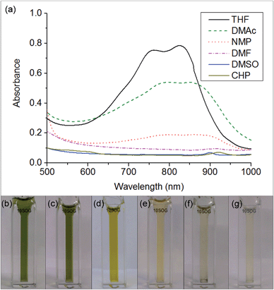
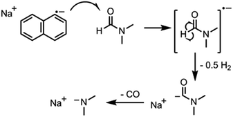
The key step in simplifying chemical reduction was to identify a stable reductant/solvent system using a nanotubide solubilising solvent, allowing the SWCNTs to both charge and dissolve in one scalable step. Known organic solvents for nanotubide include dimethyl sulfoxide (DMSO), N,N-dimethylformamide (DMF), and N-methyl-2-pyrrolidone (NMP). In addition, N-cyclohexyl-2-pyrrolidone (CHP), a related solvent to NMP previously identified as an optimum solvent for uncharged SWCNT dispersion via sonication,15 was tested. The reducing agent for the one-step system was selected from those proven to be successful in previous nanotubide literature. Direct (vapour) metal intercalation and Birch reductions were not considered compatible with a single-step process, whilst other organometallic reducing agents (such as BuLi) initiate undesirable side reactions, either with amide solvents, or by secondary alkylation of the nanotubes. As such, organic charge transfer agents were preferred and sodium naphthalide (NaNp) was selected as its reduction of SWCNTs is well studied,23 and it can be easily visually identified by a characteristic green colour. A strong reducing potential42 is desirable to maximise the charge density on the nanotubes, as long as solvent degradation is avoided.When either equimolar sodium and naphthalene or pre-synthesised NaNp crystals were stirred into DMSO, DMF, CHP and NMP at 1 mg(Na) mL−1, the solvents turned yellow/orange and increased in viscosity. The disappearance of napthalide's characteristic double peak (735 nm and 827 nm in THF, Fig. 2)42 in the UV-Vis spectra of these solutions was attributed to reaction with the solvents. The instability of NMP and CHP may relate to the opening of the strained ring. The degradation pathway of DMF in the presence of sodium metal is known43 and is initiated by reduction of DMF immediately followed by removal of the formic proton to form a metal formadyl species that can further degrade to the unstable and highly basic NaNMe2 which can decompose further DMF solvent molecules. A similar pathway was assumed to apply for the observed DMF degradation with NaNp (Scheme 1). It was proposed that replacement of the formic proton in DMF with a methyl group to form N,N′-dimethylacetamide (DMAc) would disrupt these pathways and prevent degradation. Addition of sodium and naphthalene to DMAc led to the formation of a green colour and full dissolution of sodium to produce 0.1 M solutions within 15 min stirring. The UV-Vis spectrum shows the expected naphthalide peaks at 757 and 850 nm; the small red-shift compared to the THF solution (22 nm) is attributed to the higher dielectric constant of DMAc, as seen for other charged organic complexes in varying solvents.44 The extinction coefficient in DMAc appears to be intrinsically lower than in THF (ε761 nm(THF) = 30![[thin space (1/6-em)]](https://www.rsc.org/images/entities/char_2009.gif) 200 m M−1, ε798 nm(DMAc) = 26
200 m M−1, ε798 nm(DMAc) = 26![[thin space (1/6-em)]](https://www.rsc.org/images/entities/char_2009.gif) 200 m M−1, ESI 1†). The stability of the spectrum over time excludes any ongoing reaction between the naphthalide and the solvent; the solutions obey the Beer–Lambert law upon dilution excluding the presence of a naphthalide destructive impurity (e.g. trace water contamination). To illustrate the flexibility of this DMAc system, the stability of other known SWCNT single electron transport reducing agents, potassium naphthalide31 and sodium 4,4′-di-tert-butylbiphenylide,33 was also demonstrated (ESI 4†).
200 m M−1, ESI 1†). The stability of the spectrum over time excludes any ongoing reaction between the naphthalide and the solvent; the solutions obey the Beer–Lambert law upon dilution excluding the presence of a naphthalide destructive impurity (e.g. trace water contamination). To illustrate the flexibility of this DMAc system, the stability of other known SWCNT single electron transport reducing agents, potassium naphthalide31 and sodium 4,4′-di-tert-butylbiphenylide,33 was also demonstrated (ESI 4†).
Stirring of dried SWCNT powder (Thomas Swan Elicarb) into a solution of sodium naphthalide in DMAc (NaNp/DMAc) led to rapid dissolution with a black solution of SWCNTs forming within minutes (Scheme 1), seen to be individualized SWCNTs by AFM (ESI 2†). At a set charging ratio, here C![[thin space (1/6-em)]](https://www.rsc.org/images/entities/char_2009.gif) :
:![[thin space (1/6-em)]](https://www.rsc.org/images/entities/char_2009.gif) Na = 20
Na = 20![[thin space (1/6-em)]](https://www.rsc.org/images/entities/char_2009.gif) :
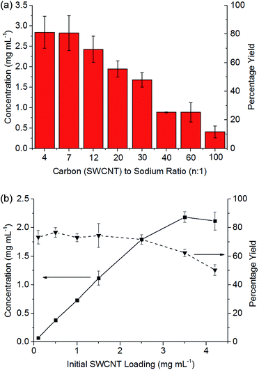
:![[thin space (1/6-em)]](https://www.rsc.org/images/entities/char_2009.gif) 1 (Fig. 3b), the concentration of nanotubide solution initially scales linearly with the loading of SWCNTs maintaining a yield between 73 and 77%, indicating that the incomplete dissolution is not due to saturation, but is due to an inherently insoluble fraction of ∼20% wt. At higher initial loadings of SWCNTs, the concentration does not increase further, causing the yield to drop as the solution appears to saturate, here at ∼2 mg mL−1.
1 (Fig. 3b), the concentration of nanotubide solution initially scales linearly with the loading of SWCNTs maintaining a yield between 73 and 77%, indicating that the incomplete dissolution is not due to saturation, but is due to an inherently insoluble fraction of ∼20% wt. At higher initial loadings of SWCNTs, the concentration does not increase further, causing the yield to drop as the solution appears to saturate, here at ∼2 mg mL−1.
At higher degrees of charge (i.e. lower C![[thin space (1/6-em)]](https://www.rsc.org/images/entities/char_2009.gif) :
:![[thin space (1/6-em)]](https://www.rsc.org/images/entities/char_2009.gif) Na ratios), the limiting solubility occurs at higher concentrations (Fig. 3a), although never at >80% yield for this SWCNT feedstock. At extremely high loadings (e.g. 6.5 mg mL−1, ESI 3†), the SWCNTs can be seen to form a gel. Increasing the degree of charge (i.e. lower C
Na ratios), the limiting solubility occurs at higher concentrations (Fig. 3a), although never at >80% yield for this SWCNT feedstock. At extremely high loadings (e.g. 6.5 mg mL−1, ESI 3†), the SWCNTs can be seen to form a gel. Increasing the degree of charge (i.e. lower C![[thin space (1/6-em)]](https://www.rsc.org/images/entities/char_2009.gif) :
:![[thin space (1/6-em)]](https://www.rsc.org/images/entities/char_2009.gif) Na ratios) with a fixed initial SWCNT loading (3.5 mg mL−1) leads to an increasing yield of SWCNTs in solution as expected due to increased coulombic repulsion; however, excessive charge is known to lead to ‘salting out’ effects31 in nanotubide solutions and polyelectrolytes in general. The concentrations here are greater than those demonstrated through NaNp charged nanotubide in DMSO (0.4 mg mL−1)23 and are on par with the sonication of predominantly bundles of SWCNTs.45 Recent research has shown speed mixing of nanotubide salts with a solvent and crown ether leads to higher concentrations (up to 52 mg mL−1), although these high concentration mixtures have not been shown to be fully individualised.15 The concentrations here (3.5 mg mL−1) are also lower than optimised sonication46 in aqueous surfactant solution (20 mg mL−1). It is worth reiterating, however, that concentrated sonicated dispersions consist primarily of bundles47 unlike spontaneously dispersed nanotubide solutions.24
Na ratios) with a fixed initial SWCNT loading (3.5 mg mL−1) leads to an increasing yield of SWCNTs in solution as expected due to increased coulombic repulsion; however, excessive charge is known to lead to ‘salting out’ effects31 in nanotubide solutions and polyelectrolytes in general. The concentrations here are greater than those demonstrated through NaNp charged nanotubide in DMSO (0.4 mg mL−1)23 and are on par with the sonication of predominantly bundles of SWCNTs.45 Recent research has shown speed mixing of nanotubide salts with a solvent and crown ether leads to higher concentrations (up to 52 mg mL−1), although these high concentration mixtures have not been shown to be fully individualised.15 The concentrations here (3.5 mg mL−1) are also lower than optimised sonication46 in aqueous surfactant solution (20 mg mL−1). It is worth reiterating, however, that concentrated sonicated dispersions consist primarily of bundles47 unlike spontaneously dispersed nanotubide solutions.24
3.2. Functionalisation of reduced SWCNT solutions
Chemical modification of SWCNTs allows adjustment of solubility,48 wettability,49 and introduction of new functionalities. Nanotubide solutions synthesised by reduction and dissolution with NaNp/DMAc are capable of reacting with alkyl halides to graft organic moieties, providing a quick non-damaging and simple route to grafted SWCNTs from the raw powder. The functionalisation of nanotubide solutions in DMAc was studied on a model series of alkyl halides. Firstly, the effect of varying halide leaving group was explored by reacting NaNp/DMAc reduced SWCNTs, changed at 20![[thin space (1/6-em)]](https://www.rsc.org/images/entities/char_2009.gif) :
:![[thin space (1/6-em)]](https://www.rsc.org/images/entities/char_2009.gif) 1 C
1 C![[thin space (1/6-em)]](https://www.rsc.org/images/entities/char_2009.gif) :
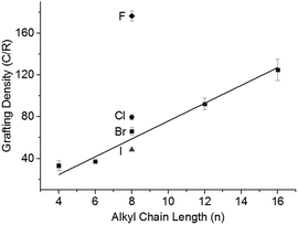
:![[thin space (1/6-em)]](https://www.rsc.org/images/entities/char_2009.gif) Na, with the 1-halide octanes (C8H17X; X = F, Cl, Br, I), followed by quenching with dry oxygen, filtering, and washing. Grafting density (alkyl groups per SWCNT carbon; lower numbers indicate higher levels of functionalisation) was calculated via TGA (ESI 8†). There is a distinct trend of increasing halide weight increasing the level of functionalisation (Fig. 4); similar to the effect seen for functionalisation of graphite intercalation compounds (GICs),50 which can be rationalised with the single electron transport mechanism.36 The increasing polarisability (and less negative reduction potentials)51 of alkyl halides along the series F < Cl < Br < I dictates the ease of radical anion formation through reduction by nanotubide, leading to a higher concentration of alkyl radicals formed for the heavier, polarisable alkyl halides with less negative reduction potentials, and a subsequently higher grafting density on the SWCNTs.
Na, with the 1-halide octanes (C8H17X; X = F, Cl, Br, I), followed by quenching with dry oxygen, filtering, and washing. Grafting density (alkyl groups per SWCNT carbon; lower numbers indicate higher levels of functionalisation) was calculated via TGA (ESI 8†). There is a distinct trend of increasing halide weight increasing the level of functionalisation (Fig. 4); similar to the effect seen for functionalisation of graphite intercalation compounds (GICs),50 which can be rationalised with the single electron transport mechanism.36 The increasing polarisability (and less negative reduction potentials)51 of alkyl halides along the series F < Cl < Br < I dictates the ease of radical anion formation through reduction by nanotubide, leading to a higher concentration of alkyl radicals formed for the heavier, polarisable alkyl halides with less negative reduction potentials, and a subsequently higher grafting density on the SWCNTs.
The steric bulk of the alkyl radical also affected the degree of functionalisation; as the reactivity of n-alkyl radicals do not vary significantly,52 any change in grafting density when varying alkyl length is attributed primarily to steric effects. On grafting a series of linear alkyl bromides (CnH2n+1Br where n = 4, 6, 8, 12, 16) to 20![[thin space (1/6-em)]](https://www.rsc.org/images/entities/char_2009.gif) :
:![[thin space (1/6-em)]](https://www.rsc.org/images/entities/char_2009.gif) 1 charged NaNp/DMAc reduced SWCNTs, a linear decrease in grafting can be seen with increasing alkyl length (Fig. 4). This near linear trend of alkyl chain length versus grafting ratio has also been observed before for GICs.50,53
1 charged NaNp/DMAc reduced SWCNTs, a linear decrease in grafting can be seen with increasing alkyl length (Fig. 4). This near linear trend of alkyl chain length versus grafting ratio has also been observed before for GICs.50,53
Even with a highly effective leaving group and short chain (C4H9Br), the grafting density remains below the 20![[thin space (1/6-em)]](https://www.rsc.org/images/entities/char_2009.gif) :
:![[thin space (1/6-em)]](https://www.rsc.org/images/entities/char_2009.gif) 1 C/R that would correspond with 100% utilisation of the 20
1 C/R that would correspond with 100% utilisation of the 20![[thin space (1/6-em)]](https://www.rsc.org/images/entities/char_2009.gif) :
:![[thin space (1/6-em)]](https://www.rsc.org/images/entities/char_2009.gif) 1 charge used to reduce the system. Some charge will be lost creating radicals which react to form dimers,53 although previous work has demonstrated that the quantity of dimer produced is small.35 An alternative limit to the reaction occurs as the nanotubide loses charge during the reaction and the Fermi level drops eventually beneath the reduction potential of the alkyl halide. Related phenomena have been demonstrated previously via the reactivity of analogous reduced graphene sheets with metal salts.54
1 charge used to reduce the system. Some charge will be lost creating radicals which react to form dimers,53 although previous work has demonstrated that the quantity of dimer produced is small.35 An alternative limit to the reaction occurs as the nanotubide loses charge during the reaction and the Fermi level drops eventually beneath the reduction potential of the alkyl halide. Related phenomena have been demonstrated previously via the reactivity of analogous reduced graphene sheets with metal salts.54
Altering the degree of charge on the nanotubide by varying the C![[thin space (1/6-em)]](https://www.rsc.org/images/entities/char_2009.gif) :
:![[thin space (1/6-em)]](https://www.rsc.org/images/entities/char_2009.gif) Na ratio also impacts the degree of grafting. At low charge ratios, there is less charge available for functionalisation and grafting levels are low; however, at high levels of charge the degree of grafting also decreases (Fig. 5). This behaviour can be explained by polyelectrolyte ‘salting out’ discussed earlier, leading to bundling of the SWCNTs reducing accessible surface area for grafting. The competition of these two effects (insufficient charge and salting out) leads to an ideal charge ratio for maximising the grafting of SWCNTs.
Na ratio also impacts the degree of grafting. At low charge ratios, there is less charge available for functionalisation and grafting levels are low; however, at high levels of charge the degree of grafting also decreases (Fig. 5). This behaviour can be explained by polyelectrolyte ‘salting out’ discussed earlier, leading to bundling of the SWCNTs reducing accessible surface area for grafting. The competition of these two effects (insufficient charge and salting out) leads to an ideal charge ratio for maximising the grafting of SWCNTs.
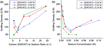 | ||
Fig. 5 Grafting density of reduced SWCNTs added to 1-bromododecane versus (a) C![[thin space (1/6-em)]](https://www.rsc.org/images/entities/char_2009.gif) : :![[thin space (1/6-em)]](https://www.rsc.org/images/entities/char_2009.gif) Na ratio, (b) sodium concentration, illustrating a shifting ideal stoichiometry but a stable sodium concentration. Na ratio, (b) sodium concentration, illustrating a shifting ideal stoichiometry but a stable sodium concentration. | ||
However, by changing the SWCNT loading, the ideal charge ratio shifts due to the changing concentration of sodium. By plotting the degree of grafting as a function of sodium concentration (Fig. 5b), a consistent ideal sodium concentration of ∼25 mM can be identified. This effect has previously been seen for grafting of alkyl halides to exfoliated sodium graphite intercalation compounds,50 at a lower concentration of ∼10 mM. Despite the higher ionic concentration, the Debye length in the DMAc/SWCNT system is calculated to be 2.7 nm, greater than the value of 1.1 nm seen for exfoliated reduced graphite in THF, due to the higher dielectric constant of DMAc relative to THF (εTHF = 7.5, εDMAc = 37.8); although the Debye lengths are similar (around 1–2 nm), the effect of changing geometry from planar to rod-like remains an open theoretical question.
3.3. Reductive purification of SWCNTs
It has been previously reported that (electro)chemical reductive dissolution of a SWCNT sample proceeds via initial dissolution of impurities and short defective nanotubes, followed by the SWCNTs at higher reduction potentials, providing a path to SWCNT purification.24 During reductive purification with NaNp/DMAc, the system potential was fixed by maintaining a fixed stoichiometry of sodium to SWCNT, analogous to the potentiostatic approach used in electrochemical purification.55 The NaNp/DMAc solution was simply poured over the dried SWCNTs; the solutions were not stirred in order maximise any kinetic difference in dissolution of impurities and SWCNTs. Increasing charge can be seen to lead to increasing dissolution of material, though a lack of stirring led to lower levels of dissolution than the stirred counterparts (Fig. 3).Purification with low levels of NaNp (≥30![[thin space (1/6-em)]](https://www.rsc.org/images/entities/char_2009.gif) :
:![[thin space (1/6-em)]](https://www.rsc.org/images/entities/char_2009.gif) 1 C
1 C![[thin space (1/6-em)]](https://www.rsc.org/images/entities/char_2009.gif) :
:![[thin space (1/6-em)]](https://www.rsc.org/images/entities/char_2009.gif) Na) leads to the dissolution of small levels of material (Fig. 6) which TEM (ESI 5†) and SEM (ESI 6†) show is not CNTs; however, significant levels of carbonaceous impurities also remain in the purified fraction. Higher charge regimes increase the purity of the sample substantially, however at extreme charging regimes (≥10
Na) leads to the dissolution of small levels of material (Fig. 6) which TEM (ESI 5†) and SEM (ESI 6†) show is not CNTs; however, significant levels of carbonaceous impurities also remain in the purified fraction. Higher charge regimes increase the purity of the sample substantially, however at extreme charging regimes (≥10![[thin space (1/6-em)]](https://www.rsc.org/images/entities/char_2009.gif) :
:![[thin space (1/6-em)]](https://www.rsc.org/images/entities/char_2009.gif) 1 C
1 C![[thin space (1/6-em)]](https://www.rsc.org/images/entities/char_2009.gif) :
:![[thin space (1/6-em)]](https://www.rsc.org/images/entities/char_2009.gif) Na) a significant proportion of the material is dissolved including the removal of pristine SWCNTs, illustrated by a reduction in the D/G Raman ratio of the dissolved fraction (ESI 7†). Furthermore, above 20
Na) a significant proportion of the material is dissolved including the removal of pristine SWCNTs, illustrated by a reduction in the D/G Raman ratio of the dissolved fraction (ESI 7†). Furthermore, above 20![[thin space (1/6-em)]](https://www.rsc.org/images/entities/char_2009.gif) :
:![[thin space (1/6-em)]](https://www.rsc.org/images/entities/char_2009.gif) 1 C/Na, the quality of the purified sample does not increase notably with similar levels of carbonaceous impurities seen for 20
1 C/Na, the quality of the purified sample does not increase notably with similar levels of carbonaceous impurities seen for 20![[thin space (1/6-em)]](https://www.rsc.org/images/entities/char_2009.gif) :
:![[thin space (1/6-em)]](https://www.rsc.org/images/entities/char_2009.gif) 1 and 10
1 and 10![[thin space (1/6-em)]](https://www.rsc.org/images/entities/char_2009.gif) :
:![[thin space (1/6-em)]](https://www.rsc.org/images/entities/char_2009.gif) 1 fractions, despite a further 34 wt% of the initial SWCNT sample dissolving (Fig. 6a); to prevent unnecessary loss of material during purification, an optimum C
1 fractions, despite a further 34 wt% of the initial SWCNT sample dissolving (Fig. 6a); to prevent unnecessary loss of material during purification, an optimum C![[thin space (1/6-em)]](https://www.rsc.org/images/entities/char_2009.gif) :
:![[thin space (1/6-em)]](https://www.rsc.org/images/entities/char_2009.gif) Na ratio (around 20
Na ratio (around 20![[thin space (1/6-em)]](https://www.rsc.org/images/entities/char_2009.gif) :
:![[thin space (1/6-em)]](https://www.rsc.org/images/entities/char_2009.gif) 1 for Elicarb SWCNTs) should be applied. The purified materials (20
1 for Elicarb SWCNTs) should be applied. The purified materials (20![[thin space (1/6-em)]](https://www.rsc.org/images/entities/char_2009.gif) :
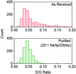
:![[thin space (1/6-em)]](https://www.rsc.org/images/entities/char_2009.gif) 1) show a decrease in average the D/G ratio (Fig. 7), due to the removal of the highly defective materials; the distribution of D/G measurements around 0.05 remains similar, implying that remaining SWCNTs are undamaged. As higher concentrations and yields of nanotubide can be seen for stirred samples compared to fractions removed during the unstirred purification at similar stoichiometries, it can be assumed that the concentration values obtained from dissolution during purification are not due to saturation. The material dissolved in purification is thought to be driven kinetically with smaller impurities able to dissolve out of the bulk, driven in part by coulombic repulsion from the rest the sample. SWCNTs will be limited to reptation out of the network which is slow due to their high lengths (diffusion time of SWCNT reptation is inversely proportional to length cubed)56 leading to the majority of SWCNTs being kinetically trapped in the bulk network. Increasing the charge density of the system swells the network through coulombic repulsion, allowing longer SWCNTs to escape. In addition, while the charge density of a specific carbon/inorganic species will depend on its density of states and defect concentration, the distribution of sodium between dissolved and undissolved materials (ESI 10†) implies that the majority of charge remains in the undissolved material leading to the conclusion that the purification is not thermodynamically driven. By introducing stirring, the networks are physically agitated, and the concentration gradient between undissolved material surface and bulk solution reduced,57 accelerating the reptation and dissolution of the SWCNTs and lowering the difference in timescale between impurity and SWCNT dissolution. Here, the concentration of the material dissolved will be limited by saturation or percentage of material which is intrinsically soluble, as seen for standard dissolution of SWCNTs using DMAc/NaNp and stirring (Fig. 3). The purification of SWCNTs benefits subsequent functionalisation; the removal of impurities increases the degree of functionalisation (ESI 11†) by allowing a greater percentage of the charge added to the system to be held on the SWCNTs increasing the available charge for functionalisation, as well as removing carbonaceous debris known to hinder functionalisation.58
1) show a decrease in average the D/G ratio (Fig. 7), due to the removal of the highly defective materials; the distribution of D/G measurements around 0.05 remains similar, implying that remaining SWCNTs are undamaged. As higher concentrations and yields of nanotubide can be seen for stirred samples compared to fractions removed during the unstirred purification at similar stoichiometries, it can be assumed that the concentration values obtained from dissolution during purification are not due to saturation. The material dissolved in purification is thought to be driven kinetically with smaller impurities able to dissolve out of the bulk, driven in part by coulombic repulsion from the rest the sample. SWCNTs will be limited to reptation out of the network which is slow due to their high lengths (diffusion time of SWCNT reptation is inversely proportional to length cubed)56 leading to the majority of SWCNTs being kinetically trapped in the bulk network. Increasing the charge density of the system swells the network through coulombic repulsion, allowing longer SWCNTs to escape. In addition, while the charge density of a specific carbon/inorganic species will depend on its density of states and defect concentration, the distribution of sodium between dissolved and undissolved materials (ESI 10†) implies that the majority of charge remains in the undissolved material leading to the conclusion that the purification is not thermodynamically driven. By introducing stirring, the networks are physically agitated, and the concentration gradient between undissolved material surface and bulk solution reduced,57 accelerating the reptation and dissolution of the SWCNTs and lowering the difference in timescale between impurity and SWCNT dissolution. Here, the concentration of the material dissolved will be limited by saturation or percentage of material which is intrinsically soluble, as seen for standard dissolution of SWCNTs using DMAc/NaNp and stirring (Fig. 3). The purification of SWCNTs benefits subsequent functionalisation; the removal of impurities increases the degree of functionalisation (ESI 11†) by allowing a greater percentage of the charge added to the system to be held on the SWCNTs increasing the available charge for functionalisation, as well as removing carbonaceous debris known to hinder functionalisation.58
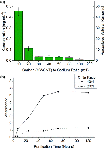 | ||
| Fig. 6 (a) Concentration of material dissolved versus C/Na after 48 h soaking of 1 mg mL−1 SWCNT in DMAc. (b) Absorbance (660 nm) of NaNp/DMAc and SWCNTs at a given SWCNT to sodium ratio versus time. | ||
4. Conclusions
In summary, a quick, simple, one-step dissolution of SWCNTs has been demonstrated through the use of DMAc as a stable solvent for both sodium naphthalide and reduced SWCNTs, enabling the synthesis of concentrated solutions of nanotubide. Additionally, the inherent scalability of the NaNp/DMAc process provides a potentially large-scale source of individualised SWCNTs, of particular use for electronic devices and high surface area applications including electrochemical electrodes and catalyst supports. The concentrations of these solutions are notably high for individualised SWCNT solutions, particularly compared to the individualised fraction of ultracentrifuged SWCNT dispersions (<0.01 mg mL−1).59 However, the use of relatively large volumes of solvent may favour initial applications in high value/high performance applications of individualised SWCNTs, for example in thin films and devices. Higher concentrations may be obtained in future if a nematic phase can be isolated and/or with the addition of complexing agents for the sodium counter-ions.60These solutions can be easily functionalised with a host of known reagents and the extent of grafting can be maximised by decreasing the steric bulk of the grafting species and using a leaving group with high polarisability. The extent of functionalisation can be seen to be a function of counter cation concentration with an idealized concentration of 25 mmol dm−3 giving a maximum grafting ratio. Additionally, modifying this method allows quick and simple access to reductive purification55 and the option to sequentially add further NaNp solution to directly dissolve the purified material. It is hoped that this work will facilitate and expand research in the versatile field of nanotubide chemistry by providing a relatively convenient route to their creation using cheap, available and easy to handle reagents.
Acknowledgements
The author would like to thank Thomas Swan Ltd. and the EPSRC (EP/G007314/1, EP/L001896/1) the support of this research and S. Hodge for development of the reductive purification methodology. The authors would also like to acknowledge funding from the Leverhulme Trust with additional support provided by an ERC starting grant (#257182).References
- A. Eatemadi, D. Hadis, H. Karimkhanloo, M. Kouhi, N. Zarghami, A. Akbarzadeh, M. Abasi, Y. Hanifehpour and S. W. Joo, Nanoscale Res. Lett., 2014, 9, 1–13 CrossRef CAS PubMed.
- S. Hodge, M. Bayazit, K. Coleman and M. Shaffer, Chemical Society Reviews, 2012, 41, 4409–4429 RSC.
- J. Hone, M. C. Llaguno, M. J. Biercuk, A. T. Johnson, B. Batlogg, Z. Benes and J. E. Fischer, Appl. Phys. A, 2002, 74, 339–343 CrossRef CAS.
- L. A. Girifalco, M. Hodak and R. S. Lee, Phys. Rev. B: Condens. Matter Mater. Phys., 2000, 62, 13104–13110 CrossRef CAS.
- T. Hasan, V. Scardaci, P. H. Tan, A. G. Rozhin, W. I. Milne and A. C. Ferrari, J. Phys. Chem. C, 2007, 111, 12594–12602 CAS.
- M. F. Yu, B. S. Files, S. Arepalli and R. S. Ruoff, Phys. Rev. Lett., 2000, 84, 5552–5555 CrossRef CAS.
- S. Reich, C. Thomsen and P. Ordejon, Phys. Rev. B, 2002, 65, 155411 CrossRef.
- Y. Wang, H. Shan, R. Hauge, M. Pasquali and R. Smalley, J. Phys. Chem. B, 2007, 111, 1249–1252 CrossRef CAS PubMed.
- T.-J. Park, S. Banerjee, T. Hemraj-Benny and S. S. Wong, J. Mater. Chem., 2006, 16, 2 RSC.
- W. Guo, Z. Dou, H. Li, Z. Shi, H. Sun and Y. Liu, Carbon, 2010, 48, 3769–3777 CrossRef CAS PubMed.
- T. Shastry, A. Morris-Cohen, E. Weiss and M. Hersam, J. Am. Chem. Soc., 2013, 135, 6750–6753 CrossRef CAS PubMed.
- H. Wang, J. Mei, P. Liu, K. Schmidt, G. Jimenez-Oses, S. Osuna, L. Fang, C. J. Tassone, A. P. Zoombelt, A. N. Sokolov, K. N. Houk, M. F. Toney and Z. Bao, ACS Nano, 2013, 7, 2659–2668 CrossRef CAS PubMed.
- M. Zheng, A. Jagota, E. D. Semke, B. A. Diner, R. S. McLean, S. R. Lustig, R. E. Richardson and N. G. Tassi, Nat. Mater., 2003, 2, 338–342 CrossRef CAS PubMed.
- S. Bergin, Z. Sun, D. Rickard, P. Streich, J. Hamilton and J. Coleman, ACS Nano, 2009, 3, 2340–2350 CrossRef CAS PubMed.
- S. Bergin, Z. Sun, P. Streich and J. Hamilton, J. Phys. Chem. C, 2009, 114, 231–237 Search PubMed.
- S. Barman, D. Pan, M. Vosgueritchian, A. Zoombelt, G. Galli and Z. Bao, Nanotechnology, 2012, 23, 344011 CrossRef CAS PubMed.
- A. Lucas, C. Zakri, M. Maugey, M. Pasquali, P. Schoot and P. Poulin, J. Phys. Chem. C, 2009, 113, 20599–20605 CAS.
- H. Yoon, M. Yamashita, S. Ata, D. Futaba, T. Yamada and K. Hata, Sci. Rep., 2014, 4, 3907 Search PubMed.
- A. Suri and K. S. Coleman, Carbon, 2011, 49, 3031–3038 CrossRef CAS PubMed.
- M. N. Tchoul, W. T. Ford, G. Lolli, D. E. Resasco and S. Arepalli, Chem. Mater., 2007, 19, 5765–5772 CrossRef CAS.
- B. Gebhardt, F. Hof, C. Backes, M. Müller, T. Plocke, J. Maultzsch, C. Thomsen, F. Hauke and A. Hirsch, J. Am. Chem. Soc., 2011, 133, 19459–19473 CrossRef CAS PubMed.
- A. Zandiatashbar, G.-H. Lee, S. An, S. Lee, N. Mathew, M. Terrones, T. Hayashi, C. Picu, J. Hone and N. Koratkar, Nat. Commun., 2014, 5, 3186 Search PubMed.
- A. Pénicaud, P. Poulin, A. Derré, E. Anglaret and P. Petit, J. Am. Chem. Soc., 2005, 127, 8–9 CrossRef PubMed.
- S. Fogden, C. Howard, R. Heenan, N. Skipper and M. Shaffer, ACS Nano, 2012, 6, 54–62 CrossRef CAS PubMed.
- A. Parra-Vasquez, N. Behabtu, M. Green, C. Pint, C. Young, J. Schmidt, E. Kesselman, A. Goyal, P. Ajayan, Y. Cohen, Y. Talmon, R. Hauge and M. Pasquali, ACS Nano, 2010, 4, 3969–3978 CrossRef CAS PubMed.
- V. A. Davis, L. M. Ericson, A. N. G. Parra-Vasquez, H. Fan, Y. Wang, V. Prieto, J. A. Longoria, S. Ramesh, R. K. Saini, C. Kittrell, W. E. Billups, W. W. Adams, R. H. Hauge, R. E. Smalley and M. Pasquali, Macromolecules, 2004, 37, 154–160 CrossRef CAS.
- P. K. Rai, A. N. G. Parra-Vasquez, J. Chattopadhyay, R. A. Pinnick, F. Liang, A. K. Sadana, R. H. Hauge, W. E. Billups and M. Pasquali, J. Nanosci. Nanotechnol., 2007, 7, 3378–3385 CrossRef CAS PubMed.
- V. Davis, A. Parra-Vasquez, M. Green, P. Rai, N. Behabtu, V. Prieto, R. Booker, J. Schmidt, E. Kesselman, W. Zhou, H. Fan, W. Adams, R. Hauge, J. Fischer, Y. Cohen, Y. Talmon, R. Smalley and M. Pasquali, Nat. Nanotechnol., 2009, 4, 830–834 CrossRef CAS PubMed.
- S. Hodge, M. Bayazit, H. Tay and M. Shaffer, Nat. Commun., 2013, 4, 1989 Search PubMed.
- M. K. Bayazit, A. Suri and K. S. Coleman, Carbon, 2010, 48, 3412–3419 CrossRef CAS PubMed.
- D. Voiry, C. Drummond and A. Pénicaud, Soft Matter, 2011, 7, 7998–8001 RSC.
- A. Pénicaud, F. Dragin, G. Pécastaings, M. He and E. Anglaret, Carbon, 2014, 67, 360–367 CrossRef PubMed.
- A. García-Gallastegui, I. Obieta, I. Bustero, G. Imbuluzqueta, J. Arbiol, J. I. Miranda and J. M. Aizpurua, Chem. Mater., 2008, 20, 4433–4438 CrossRef.
- J. Guan, Y. Martinez-Rubi, S. Dénommée, D. Ruth, C. Kingston, M. Daroszewska, M. Barnes and B. Simard, Nanotechnology, 2009, 20, 245701 CrossRef PubMed.
- D. Voiry, O. Roubeau and A. Pénicaud, J. Mater. Chem., 2010, 20, 4385–4391 RSC.
- J. Chattopadhyay, S. Chakraborty, A. Mukherjee, R. Wang, P. S. Engel and W. E. Billups, J. Phys. Chem. C, 2007, 111, 17928–17932 CAS.
- F. Liang, A. K. Sadana, A. Peera, J. Chattopadhyay, Z. Gu, R. H. Hauge and W. E. Billups, Nano Lett., 2004, 4, 1257–1260 CrossRef CAS.
- Z. Syrgiannis, L. V. Parola, C. Hadad, M. Lucío, E. Vázquez, F. Giacalone and M. Prato, Angew. Chem. Int. Ed., 2013, 52, 6480–6483 CrossRef CAS PubMed.
- F. Hof, F. Hauke and A. Hirsch, Chem. Commun., 2014, 50, 6582–6584 RSC.
- Y. Martinez-Rubi, B. Ashrafi, J. Guan, C. Kingston, A. Johnston, B. Simard, V. Mirjalili, P. Hubert, L. Deng and R. J. Young, ACS Appl. Mater. Interfaces, 2011, 3, 2309–2317 CAS.
- F. Liang, J. M. Beach, K. Kobashi, A. K. Sadana, Y. I. Vega-Cantu, J. M. Tour and W. E. Billups, Chem. Mater., 2006, 18, 4764–4767 CrossRef CAS.
- N. Connelly and W. Geiger, Chem. Rev., 1996, 96, 877–910 CrossRef CAS PubMed.
- R. Paul, B. Anand and R. Kapoor, Indian J. Chem., 1975, 13, 1338 CAS.
- N. Sarmah, P. K. Bhattacharyya and K. K. Bania, J. Phys. Chem. A, 2014, 118, 3760–3774 CrossRef CAS PubMed.
- N. Tummala and A. Striolo, ACS Nano, 2009, 3, 595–602 CrossRef CAS PubMed.
- M. F. Islam, E. Rojas, D. M. Bergey, A. T. Johnson and A. G. Yodh, Nano Lett., 2003, 3, 269–273 CrossRef CAS.
- C. Jiang, A. Saha, C. C. Young, D. P. Hashim, C. E. Ramirez, P. M. Ajayan, M. Pasquali and A. A. Martí, ACS Nano, 2014, 8, 9107–9112 CrossRef CAS PubMed.
- R. Chadwick, U. Khan, J. Coleman and A. Adronov, Small, 2013, 9, 552–560 CrossRef CAS PubMed.
- Y. Martinez-Rubi, B. Ashrafi, J. Guan, C. Kingston, A. Johnston, B. Simard, V. Mirjalili, P. Hubert, L. Deng and R. Young, ACS Appl. Mater. Interfaces, 2011, 3, 2309–2317 CAS.
- T. Morishita, A. J. Clancy and M. S. P. Shaffer, J. Phys. Chem. A, 2014, 2, 15022–15028 CAS.
- A. A. Isse, C. Lin, M. L. Coote and A. Gennaro, J. Phys. Chem. B, 2010, 115, 678–684 CrossRef PubMed.
- D. V. Avila, K. U. Ingold, J. Lusztyk, W. R. Dolbier, H. Q. Pan and M. Muir, J. Am. Chem. Soc., 1994, 116, 99–104 CrossRef CAS.
- G. D. Sargent and G. A. Lux, J. Am. Chem. Soc., 1968, 90, 7160–7162 CrossRef CAS.
- S. A. Hodge, H. H. Tay, D. B. Anthony, R. Menzel, D. J. Buckley, P. L. Cullen, N. T. Skipper, C. A. Howard and M. S. P. Shaffer, Faraday Discuss., 2014, 172, 311–325 CAS.
- S. Hodge, S. Fogden, C. Howard, N. Skipper and M. Shaffer, ACS Nano, 2013, 7, 1769–1778 CrossRef CAS PubMed.
- N. Fakhri, F. C. MacKintosh, B. Lounis, L. Cognet and M. Pasquali, Science, 2010, 330, 1804–1807 CrossRef CAS PubMed.
- T. Twardowski, Introduction to Nanocomposite Materials, DEStech Publications Inc, 2007 Search PubMed.
- L. Shao, G. Tobias, C. G. Salzmann, B. Ballesteros, S. Y. Hong, A. Crossley, B. G. Davis and M. L. Green, Chem. Commun., 2007, 5090–5092, 10.1039/b712614j.
- S. Giordani, S. D. Bergin, V. Nicolosi, S. Lebedkin, M. M. Kappes, W. J. Blau and J. N. Coleman, J. Phys. Chem. B, 2006, 110, 15708–15718 CrossRef CAS PubMed.
- C. Jiang, A. Saha, C. Xiang, C. Young, J. Tour, M. Pasquali and A. Martí, ACS Nano, 2013, 7, 4503–4510 CrossRef CAS PubMed.
Footnote |
| † Electronic supplementary information (ESI) available: Supplementary figures. See DOI: 10.1039/c5ta03561a |
| This journal is © The Royal Society of Chemistry 2015 |

