
 Open Access Article
 This Open Access Article is licensed under a
 Creative Commons Attribution 3.0 Unported Licence
Boron-doped onion-like carbon with enriched substitutional boron: the relationship between electronic properties and catalytic performance†
Yangming
Lin
ab,
Yansong
Zhu
b,
Bingsen
Zhang
b,
Yoong Ahm
Kim
c,
Morinobu
Endo
d and
Dang Sheng
Su
*be
aSchool of Chemistry and Materials Science, University of Science and Technology of China, Hefei, 230026, China. Fax: +86-24-83970019; Tel: +86-24-83970029
bShenyang National Laboratory for Materials Science, Institute of Metal Research, Chinese Academy of Sciences, Shenyang, 110016, China. E-mail: dssu@imr.ac.cn; Fax: +86-24-83970019; Tel: +86-24-83970029
cSchool of Polymer Science and Engineering, Chonnam National University, 77 Yongbong-ro, Buk-gu Kwangju, 500-757, Korea
dCarbon Institute of Science and Technology, Shinshu University, 4-17-1 Wakasato, Nagano, 380-8553, Japan
eDepartment of Inorganic Chemistry, Fritz Haber Institute of the Max Planck Society, Faradayweg 4-6, Berlin, 14195, Germany
First published on 7th September 2015
Abstract
Incorporating heteroatoms into onion-like carbon (OLC, average size ∼5 nm) with a fullerene-like structure and investigating its peculiar properties are fascinating challenges. Here, we present straightforward fabrication of doped OLC samples with a high concentration of boron (0.63–4.57 at%) via a high-temperature thermal diffusion method. The highest proportion of substitutional boron of the boron species reaches 29%, which far exceeds most of the reported boron-doped carbon materials. The influence of boron on the fullerene-like layers and electronic properties of OLC is systematically investigated using Raman spectroscopy with different excitation energies (1.58–3.8 eV) and ultraviolet photoelectron spectroscopy (UPS). The as-prepared boron-doped OLC samples exhibit a perfect four-electron process for the oxygen reduction reaction (ORR), which is similar to commercial Pt/C. It is worth noting that the intrinsic relationship between the electronic properties and catalytic performance of doped samples is explored based on experimental studies instead of theoretical calculations. The results indicate that the lower work function, lower valence band edge and higher density of states (DOSs) of doped OLC are crucial to improve the catalytic performance. Our work can provide valuable information on the design of doped metal-free materials and give new evidence for enhanced ORR activity associated with heteroatom doping and electronic properties.
Introduction
Since onion-like carbon (OLC) was found and described for the first time by Iijima, its structure has been envisioned to be quasi-spherical nanoparticles consisting of multilayer concentric fullerene-like shells.1–3 In contrast to those of graphene, carbon nanotubes (CNTs) and carbon fibers (CNFs), OLC has specific p and π electronic structures due to its high curvature.4,5 Over the past few years, OLC as a fascinating material has stimulated a great deal of research in various fields, including supercapacitors,6 supports,7 Li-ion batteries,8 catalysis,9 tribology10 and electromagnetic shielding.11 There are many synthetic methods for OLC-related materials such as plasma spraying,12 laser irradiation,13 chemical vapor deposition (CVD)14 and arc-discharge,15 but the annealing of detonation nanodiamond powders (UDD) in an inert atmosphere or in a vacuum (T > 1200 °C) is the only widely used one that allows the synthesis of a large amount of OLC at low cost.16Chemical doping in carbon materials using heteroatoms (e.g. N, S, O and P) is a common strategy to effectively modulate their intrinsic electronic characteristics, surface and local chemical features.17–19 Boron atoms could be incorporated into the carbon matrix because they have a comparable atomic size and three valence electrons for binding with carbon atoms. The formed B–C bond is longer than the C–C bond (ca. 0.5%), leading to the chemical disorder of graphite layers, and obtaining p-type (or hole) doped carbon materials.20 Recently, the fabrication of boron-doped carbon materials with excellent physicochemical properties has been the research hotspot by using the traditional annealing treatment (T < 1200 °C), CVD method and plasma etching.21–23 For instance, Park et al. described that the boron-doped graphene exhibited a higher specific capacitance than typical carbon-based supercapacitor materials after surface area-normalized capacitance, attributed to the effect of boron atoms on the electronic structure.24 Cheng and co-workers reported that boron-doped graphene as an anode material had high rate capability and large capacity in lithium ion batteries.25 Kim et al. showed that boron-doped CNTs could effectively improve electron–hole transport in solar cells.26 Despite these great achievements, the low doping level of boron, the low yield, the deficiency of substitutional boron (BC3) and the vague identification of boron species still hinder the study of these doped carbon materials to a great extent. Therefore, it is very meaningful to explore a novel heteroatom-doped carbon material (e.g. OLC) with a high concentration of BC3 species and the mixed textures of planar graphene and curved CNTs, and further investigate its unique electronic properties.
The oxygen reduction reaction (ORR) is a very important process in many fields, including energy conversion,27 corrosion28 and biosensing.29 Recently, metal-free electrocatalysts have attracted a great deal of interest due to their potentially low-cost, high abundance and much better stability toward CO and methanol poisoning than the state-of-the-art Pt catalyst.30–36 In some cases, the obtained catalysts in the presence of heteroatoms exhibit excellent catalytic activity (onset potential) comparable to that of Pt/C.37,38 Wang et al. summarized the current progress of the ORR mechanism in metal-free electrocatalysis and believed that the presence of heteroatoms would change the atomic spin, charge densities, band structure and electronic states of carbon materials and hence could improve the ORR activity.39 However, the understanding of the ORR mechanism and electronic structure of the doped metal-free carbon catalysts is still limited to predictions based on theoretical calculations. Experimental studies for insight into the relationship between ORR activity and electronic properties are still rare.
In the present study, we report a systematic study on the preparation of boron-doped OLC (B-OLC) samples via a high temperature thermal treatment (1500–2400 °C) starting from nanodiamonds in a graphite furnace. The boron content in B-OLC samples could be simply tuned by varying the amount of boron source. The detailed preparation process is shown in Scheme 1. Our aim is to investigate the effect of the enriched substitutional boron atoms on the ordered structure and electronic properties of fullerene-like layers, and then use experimental studies to systematically correlate the impact of heteroatom doping in nanocarbons with enhanced ORR activity instead of theoretical calculations.
 | ||
| Scheme 1 Schematic illustration of the fabrication of various B-OLC samples (seven fullerene-like shells as an ideal structure represent the sp2 carbon shells of OLC). | ||
Experimental section
Materials
Purified ultra-dispersed nanodiamonds (UDDs) were bought from Beijing Grish Hitech Co. (China), produced by detonation and followed by acid washing. The average particle size was about 5 nm. Boric acid (H3BO3) (Aladdin Co. high purity, 99.999%) was chosen as the dopant.Sample preparation and activity test
The various boron-doped samples were produced by the following procedures: (1) the mixture with 5 wt% boric acid and ultra-dispersed nanodiamonds (UDDs) was produced by manual mixing for 1 h and then the sample was thermally treated from 25 °C to 100 °C at a very slow heating rate of 0.5 K min−1 in a graphite furnace under an argon atmosphere. (2) The obtained mixture was further annealed at 1500 °C, 1800 °C, 2100 °C and 2400 °C for 30 min at a heating rate of 5 K min−1 in a graphite furnace under an argon atmosphere. The final products were labeled as B-OLC-1-5, B-OLC-2-5, B-OLC-3-5 and B-OLC-4-5. The undoped samples OLC-1, OLC-2, OLC-3 and OLC-4 were synthesized by the same procedure without adding the boron dopant. Moreover, the 10 wt% and 20 wt% boric acid were manually mixed with the UDDs and then annealed at 1500 °C for 30 min at a heating rate of 5 K min−1 in a furnace under an argon atmosphere. These two products were denoted by B-OLC-1-10 and B-OLC-1-20, respectively.High-resolution transmission electron microscopy (HRTEM) images and electron energy loss spectroscopy (EELS) spectra were recorded on a FEI Tecnai G2 F20 microscope. The Brunauer–Emmett–Teller (BET) specific surface area measurement was conducted on a Micromeritics ASAP2020 analyzer. X-ray diffraction (XRD) patterns were measured by using a Rigaku D/Max-2500PC diffractometer with Cu Kα radiation operating at 50 kV, 300 mA. N2 adsorption–desorption analysis was conducted on the Micromeritics ASAP2020 analyzer. The X-ray photoelectron spectroscopy (XPS) and ultraviolet photoelectron spectroscopy (UPS) were carried out on an ESCALAB 250 XPS system with a monochromatized Al Ka X-ray source and a He discharge lamp (He I: hν = 21.22 eV). The corresponding XPS spectra were divided by fitting the peak maximum within ± 0.1 eV and applying a full width half-maximum (FWHM) of 1.2–1.6 eV using Avantage analysis soft. The value of the mixed Gaussian–Lorentzian was fixed at 30%. The skeletal density of the samples was determined with a TD-2200 density analyzer (Biaode, China). The content of boron in doped samples was determined by inductively coupled plasma optical emission spectroscopy (ICP-OES). The electrical conductivity of all the samples was obtained on a conventional four probe system. The Raman spectra of samples on SiO2/Si were recorded with a LabRam HR800 spectrometer and a He/Ne laser at 325 nm (15× objective), various Ar–Kr ion lasers at 532 nm (50× objective), 633 nm (50× objective) and 785 nm (50× objective) were selected as the excitation source. Moreover, the laser power and exposure time were maintained well to avoid the damage of samples and the heating effects.
Electrochemical measurements were performed using an Epsilon Electrochemical Station (PAR2273) in a conventional three-electrode electrochemical cell. To avoid any potential contamination of a non-precious metal catalyst by platinum, experiments were carried out using a graphite rod as the counter electrode. An Ag/AgCl electrode in 3.0 M KCl (0.220 V vs. NHE) was used as a reference electrode. All potentials were later converted to the RHE scale. The experiments were carried out at room temperature (25 °C). The boron-doped OLC samples were transferred onto the glassy carbon electrode (GCE, 5 mm diameter) according to the following procedures: (1) 18 mg catalysts were added into the solution mixture of 1 mL isopropanol and 100 μL nafion (5% w/w solution), and then ultrasonicated for 30 min. (2) 10 μL of the as-made solution mixture was dropped on the GCE surface and dried at room temperature in air without any heating process. The final loading of the catalyst on the electrode is about 0.83 mg cm−2.
The activity of the electrocatalysts was evaluated by the linear sweep voltammetry (LSV) techniques on rotating disk electrodes (RDE) in an oxygen- and nitrogen-saturated aqueous solution of 0.1 M KOH and maintained at 5 mV s−1 scan rate. The tolerate ability of the catalyst (B-OLC-1-10 and 20% Pt/C) was tested by adding methanol (3 M, 10 mL) at a constant voltage of 0.6 V in an O2 bubbled 0.1 M KOH electrolyte. The durability evaluation of Pt/C and B-OLC-1-10 samples was maintained for 10![[thin space (1/6-em)]](https://www.rsc.org/images/entities/char_2009.gif) 000 s at 0.6 V and a rotation rate of 900 rpm. Here, the loadings of B-OLC-1-10 and 20% Pt/C catalysts on the electrode were about 0.055 mg cm−2.
000 s at 0.6 V and a rotation rate of 900 rpm. Here, the loadings of B-OLC-1-10 and 20% Pt/C catalysts on the electrode were about 0.055 mg cm−2.
The Koutecky–Levich equation is
| J−1 = Bω−0.5 + JK−1 |
| B = 0.62nF(DO2)2/3 (ν−1/6)CO2 |
485 C mol−1), n is the number of electrons transferred per oxygen molecule, DO2 is the diffusion coefficient of O2 in the electrolyte (1.9 × 10⁻⁵ cm2 s−1), ν is the kinetic viscosity (0.01 cm2 s−1), and CO2 is the oxygen concentration (solubility) in the electrolyte (1.2 × 10⁻⁶ mol cm−3). The constant 0.62 is adopted when the rotation speed is expressed in rpm.
Results and discussion
X-ray photoelectron spectroscopy (XPS) was used to investigate the boron species in the samples. As displayed in Fig. 1A, the spectrum of B1s can be deconvoluted into the seven regions that correspond to the boron atom cluster (B1, ∼186.5 eV), B4C (B2, ∼187.6 eV), substitutional boron species BC3 (B3, ∼188.8 eV), BC2O (B4, ∼190.1 eV), B–N (B5, ∼190.7 eV, originating from the chemical bonding between the inherent trace nitrogen species and boron source after annealing), BCO2 (B6, ∼191.3 eV) and B2O3 (B7, >192.8 eV), respectively.40–42 The detailed results of XPS are summarized in Fig. 1B, S1A and Table S1 (ESI†). We find that on increasing the calcination temperature, the total concentration of boron atoms consecutively decreases from 1.0 at% for B-OLC-1-5 to 0.63 at% for B-OLC-4-5. Among all the doped samples, the B-OLC-4-5 has the highest content of B1 (0.27 at%), and yet the highest concentration of substituted boron species, B3 (0.3 at%) exists in B-OLC-1-5. This result indicates that the B1 species can be favorably formed at elevated temperature, leading to the decrease of the B3 species. Therefore, the optimized calcination temperature for boron doped OLC is conducted at 1500 °C to obtain highly substitutional boron species B3. Fig. 1C and D show that the concentration of boron species increases from 1.0 to 4.57 at% by simply varying the amount of boron source from 5 to 20 wt% at 1500 °C. It is worth noting that the proportions of the substitutional boron species B3 remain at 21–29%, which far exceed the doping level of the reported boron-doped carbon materials.24–26,43 The ordered graphitic structure can be revealed by the full width at half maximum (FWHM) of XPS C1s.4 Compared with the undoped OLC-1 (1.21 eV), the C1s peak of the doped sample at 284.6 eV is gradually broadened (1.30 eV and 1.34 eV, respectively) demonstrating that the introduction of boron affects the ordered structure of fullerene-like layers due to the formation of the longer boron–carbon bonds (Fig. S2A†). This result is further supported by a small carbidic boron–carbon spectral feature at about 282.7 eV, corresponding to the presence of boron atoms in fullerene-like layers. Fig. S2B† illustrates that the specific surface area of pristine OLC-1 decreases from 463 m2 g−1 to 383 m2 g−1 for B-OLC-1-20. In contrast, a slight increase in skeletal density after the incorporation of boron can be seen in doped samples (Table 1).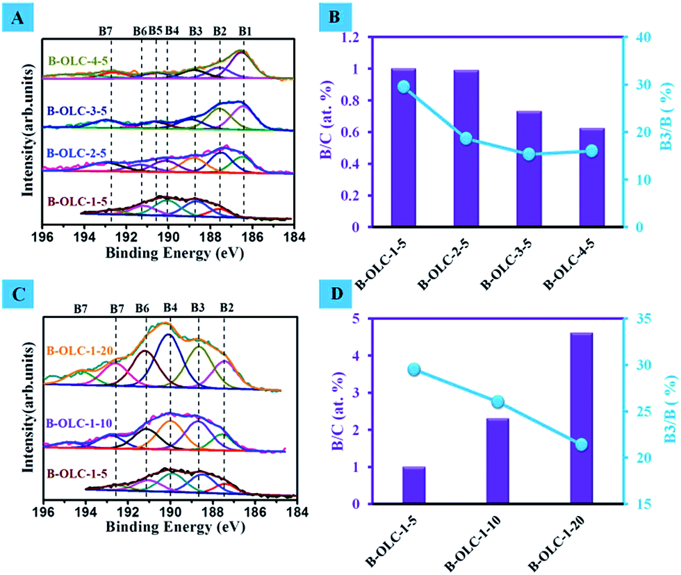 | ||
| Fig. 1 (A) XPS B1s spectra and (B) the Bx/C distribution diagram of the B-OLC samples under different calcination temperatures (from 1500 to 2400 °C) with the same content of boron source (5 wt%). (C) XPS B1s spectra of the B-OLC samples prepared at the same temperature (1500 °C) using different amounts of boron source (5, 10 and 20 wt%). (D) The Bx/C distribution diagram and proportional graph of the substitutional boron species B3 on B-OLC samples. The XPS B1s spectra were deconvoluted by fitting the peak maximum within ±0.1 eV and applying a full width half-maximum (FWHM) of 1.2–1.6 eV. The value of the mixed Gaussian–Lorentzian was fixed at 30%. | ||
| Sample | Skeletal density (g cm−3) | Boron (wt%) |
|---|---|---|
| OLC-1 | 2.15 | 0.008 |
| B-OLC-1-5 | 2.21 | 0.852 |
| B-OLC-1-10 | 2.29 | 1.631 |
| B-OLC-1-20 | 2.40 | 3.312 |
The thermostability of pristine and doped OLC under dry air and an inert atmosphere was studied by using thermogravimetric analysis (TGA). As shown in Fig. S3A,† there are no obvious changes in the combustion onset temperature (∼560 °C) after boron species are introduced. The combustion residue of pure OLC is about 0.89 wt%, which is mainly attributed to the unpurified BaKXSO4 in the original commercial UDDs (Fig. S4†). The residues of doped OLC samples are basically consistent with the amount of boron source, implying that most of the boron is introduced into the OLC. This result is further supported by inductively coupled plasma optical emission spectroscopy (ICP-OES, Table 1). In addition, the introduction of boron has no obvious influence on thermostability compared with undoped OLC under an inert atmosphere (Fig. S3B†). The mass loss slightly increases from 0.96 wt% of undoped OLC to 1.23 wt% of doped OLC. Various doped samples with different concentrations of boron species exhibit the same thermostability performance. A certain amount of mass loss of various samples can be ascribed to the surface-adsorbed water or the desorption of oxygen groups under elevated temperature conditions.
The HRTEM images in Fig. 2B–D show that the structures of OLC and doped OLC samples are composed of multilayer sp2 fullerene-like shells. The identified interlayer spacing of 0.340 nm in the shell of OLC corresponds to the (002) of turbostratic carbons–graphite. We did not observe an obvious increase in the interlayer spacing regardless of the value varying from 0.34 nm of OLC-1 to 0.348 nm of B-OLC-1-20. However, the excessive incorporated boron may disrupt the order of curved fullerene-like shells, as explained by the slight change in the structure of the B-OLC-1-20 (Fig. 2D). The particle sizes of nanodiamonds, the pristine and doped OLC samples are about 5–8 nm. Selected area electron diffraction (SAED) pattern (inset in Fig. 2A and B) results indicate that the UDDs convert effectively into the sp2 carbon phase because of the disappearance of three characteristic diffraction rings (111), (220), and (311) of UDDs and the appearance of an apparent graphite (002) ring.19,44 Besides, we did not find more diffuse diffraction rings after the boron species are incorporated into OLC (Fig. 2B–D). Some defects or amorphous carbon derived from the reconstruction of the fullerene-like structure appear on the surface of samples (marked by red arrows in Fig. 2B–D). Electron energy loss spectroscopy (EELS) was considered to be an efficient analysis method for doped carbon materials owing to their spectra corresponding to the excitation of the C1s and B1s core electrons to the empty conduction band states which show the local conduction density of states at that site.45,46 The results of EELS show the well-defined π* (∼285 eV) and the σ* (∼292.3 eV) fine structure features of the carbon K-edges (see Fig. 2E), which are characteristic of well-graphitized sp2-bonded hexagonal networks.4 As depicted in Fig. 2F, the π* peak at about 190.3 eV in the boron K-edge corresponds to the sp2 bonding of boron in hexagonal boron/carbon conformation (BC3).47,48 By systematically quantifying the chemical compositions from the EELS spectra, it is found that the as-made doped OLC samples contain 1.15, 2.24 and 3.98 at% of boron in the bulk, respectively. Moreover, the very similar spectral features between carbon and boron K-edge also reveal the incorporation of boron atoms into the carbon sp2 network, which are well consistent with the XPS results.
 | ||
| Fig. 2 (A)–(D) HRTEM images and SAED patterns (insets) of fresh UDDs, pristine OLC-1, B-OLC-1-10 and B-OLC-1-20 samples, respectively. The red arrows present the defects or amorphous carbon on the fullerene-like shells. The SAED patterns show the typical graphite and diamond structure diffraction rings in all the samples. The scale bar of SAED patterns is 2 nm−1. (E) and (F) EELS profiles of three different B-OLC samples. | ||
Raman scattering was an excellent probe for studying the electronic and phonon structure in pristine and doped carbon materials.49 Raman spectra of different samples using a 532 nm laser source exhibit various main feature bands in the 1000–2800 cm−1 region as shown in Fig. 3: the defect-induced D-band (∼1334 cm−1), the amorphous carbon structure A-band (∼1490 cm−1), the ideal graphite lattice G-band (∼1579 cm−1) and the 2D-band (∼2660 cm−1). The D-band represented the breathing mode of the aromatic ring in the carbon network and was assigned to the TO phonons of A1g symmetry at the K point of the Brillouin zone.50 The intensity and line width of the D-band were allowed as probes for the formation of a disordered structure. The value of the ID/IG ratio was frequently used for a quantitative measure of structural defects. The 2D-band was related to a phonon near the K point in carbon materials and could be activated by double resonance processes. It was responsible for the dispersive nature and caused a strong dependence on any perturbation to the electronic and/or phonon structure of carbon materials. Therefore, the 2D feature provided a very sensitive probe for characterizing specific sp2 nanocarbons.51–53 The behavior of the I2D/IG ratio does not solely depend on the π–π stacking order of the graphite layers, but also is a function of the Fermi level energy. Besides, the G-peak corresponded to the high-frequency E2g phonon at Γ and the position of the G-band implied the formation of point-like defects, the doping of holes and electrons, and thus was also highly sensitive to the doping state of carbon materials and strain effects in sp2 nanocarbon.53,54 After the introduction of boron species (Fig. 3A), the wider line width of the D-band (increases from 97 cm−1 of OLC-1 to 121 cm−1 of B-OLC-1-20) on doped samples are observed, indicating that the boron species changes the order of the fullerene-like structure to some degree. Moreover, the value of ID/IG increases from 1.9 to 2.6, revealing that the introduction of boron produces much more structural defects compared with the undoped OLC-1 sample as shown in Fig. 3C. The same phenomenon had also been reported on B-doped graphite fibers.55 On the other hand, the lower ratio of I2D/IG and the lower intensity 2D-band on the doped samples verify that the successful incorporation of boron species will disturb the stacking order of the fullerene-like layers.56,57Fig. 3B further shows that the 2D-band frequency downshifts from 2662 cm−1 for undoped OLC to 2654 cm−1 for B-OLC-1-20. This downshift presumably is that EF moves away from the Dirac point (the level will shift to a lower energy) and leads to the opening of the energy gap because of the change of electronic states near the K–M direction.57–59 In addition, we find that the presence of boron cannot improve the amorphous carbon phase of the OLC sample, which is supported by the weak change of the IA/IG value from 0.19 of the undoped OLC to 0.3 of the B-OLC-1-20 sample. Interestingly, compared with undoped OLC, we did not observe a distinctive upshift change (∼3 cm−1) of the G-band frequency on the B-OLC-1-5 and the B-OLC-1-10 samples, which may be attributed to the p-type boron doping (stiffening) partially counteracting the tensile strain effect induced by the larger carbon–boron bond length (softening).20,60,61 When the concentration of boron is further increased, an apparent upshift of the G-band that varied from 1579 cm−1 to 1587 cm−1 can be observed in the B-OLC-1-20 samples (see Fig. 3A). These results signify that boron has been successfully doped in the sp2 carbon framework of OLC and further influences the electronic structure of fullerene-like layers.
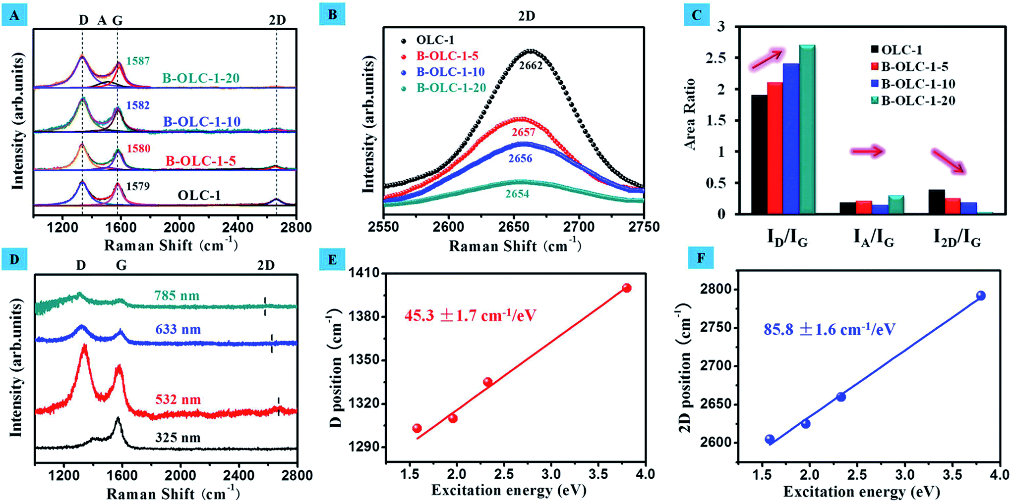 | ||
| Fig. 3 (A) The deconvolution of the first- and second-order for Raman spectra of different samples using a He–Ne laser (λ = 532 nm) and (B) the enlarged spectra of the 2D band in the 2550–2750 cm−1 region. (C) The integrated area ratios of the D band (ID/IG), A band (IA/IG) and 2D band (I2D/IG). (D) Raman spectra of the representative B-OLC-1-10 sample using different excitation sources (λ = 325 nm, 532 nm, 633 nm and 785 nm). (E) and (F) Line positions of the D band and 2D band frequencies in the B-OLC-1-10 sample as a function of excitation energy, respectively. | ||
In Fig. 3D, lasers with a wavelength from 325 nm to 785 nm were employed to further investigate the vibrational modes of the representative B-OLC-1-10 sample. With increasing excitation wavelengths, the peak position of the D-band decreases from 1400 cm−1 to 1303 cm−1 and the dispersive 2D-band varies from 2792 cm−1 to 2605 cm−1. All these dispersion behaviors can be explained by a phonon double resonance process.49 In contrast, the peak frequency of the G-band almost remains unchanged under different laser wavelengths, which is attributed to a first-order mode. Moreover, we plotted the positions of the D- and 2D-band of B-OLC-1-10 versus the excitation energy as shown in Fig. 3E and F. A good linear relationship is found and the slope of the D-band (45.3 ± 1.7 cm−1/eV) is about half of that of the 2D-band (85.8 ± 1.6 cm−1/eV). This result signifies that the incorporation of boron only partly changes the order of the fullerene-like structure instead of complete destruction. In addition, such a low value of the D-peak dispersion slope supports the hole-doped OLC by substitutional boron doping, which is further revealed by the theoretical calculation of the Raman D-peak dispersion as a function of doping.54 The strong slope behavior of the 2D-band is related to its second-order process of a phonon branch near the K point in the Brillouin zone.20,62
Ultraviolet photoelectron spectroscopy (UPS) was employed as a credible measurement for further investigating electronic structures, valence band edges and work functions of doped OLC samples. As displayed in Fig. 4A, three peaks can be observed for undoped and doped samples. A broad peak at around 3 eV is assigned as a 2p–π state.63 As the content of boron increases, the 2p–π peaks of doped OLC catalysts slightly shift to the lower binding energy (∼2.5 eV). This may be attributed to the electron transfer from carbon to boron (electron deficiency), leading to a lower shift of the Fermi level (EF). The weakening of the 2p–π + σ peak of doped samples at about 7 eV can be explained by the p-doping effect. For boron doping, all three valence electrons of boron will participate in the σ bonding with neighboring carbons, while the additional electron for π bonding will vanish.64 Additionally, a more prominent 2s–σ peak of B-OLC-1-10 compared with that of OLC-1, B-OLC-1-5 and B-OLC-1-20 at the nominal binding energy (about 13 eV) is due to a higher density of states (DOSs) in the unoccupied states originating from the interlayer band that has larger charge densities between boron and carbon planes.65,66 The downshift of this peak in doped samples as compared to pristine OLC-1 (13.1 eV) suggests that DOSs located in an energy region are more close to the EF. Moreover, Fig. 4B shows that the valence band edge decreases from the 1.27 eV for the undoped OLC to 0.84 eV for the B-OLC-1-10 sample.
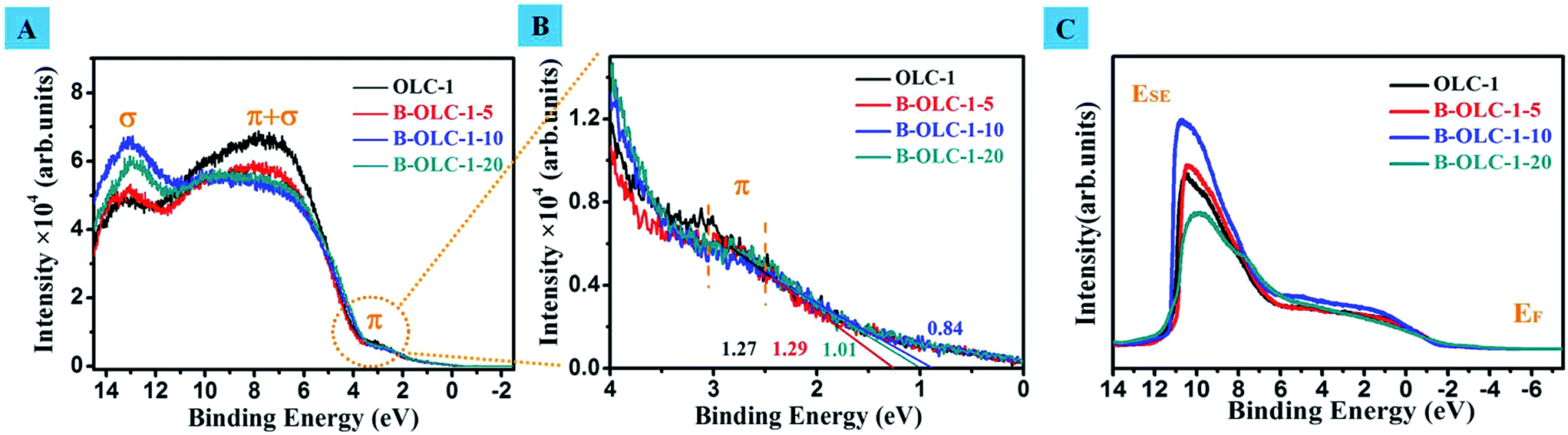 | ||
| Fig. 4 (A) UPS spectra of the undoped OLC and various doped OLC samples without bias. (B) Valence band photoemission spectra of undoped OLC and various doped OLC samples (the enlarged view of the circle at (A)). (C) UPS spectra of the undoped OLC and various doped OLC samples with bias. UPS spectra are obtained at room temperature using a He discharge lamp (He I: hν = 21.22 eV). The samples are biased by about −6 V during the work function measurements to accelerate the low energy secondary electrons (SE) and nickel metal is used as reference. The work function (Φ) = 21.22 eV − |ESE − EF|. EF is the Fermi edge. The valence band edge is calculated by the cross-over point between the tangent of photoemission spectra and the X axis. | ||
The work function (Φ) is the needed minimum energy of inner electrons that can escape from their nucleus, that is, the lower work function implies that the electrons of samples have a lower energetic barrier and are more likely to be motivated under reaction conditions.67 As shown in Fig. 4C, the calculated Φ value of B-OLC-1-10 is 4.10 eV, which is far less than that of OLC (4.42 eV), B-OLC-1-5 (4.48 eV) and B-OLC-1-20 (4.28 eV) as well as that of most of the reported boron or other heteroatom-doped carbon materials (3.9–5.1 eV).17,68,69
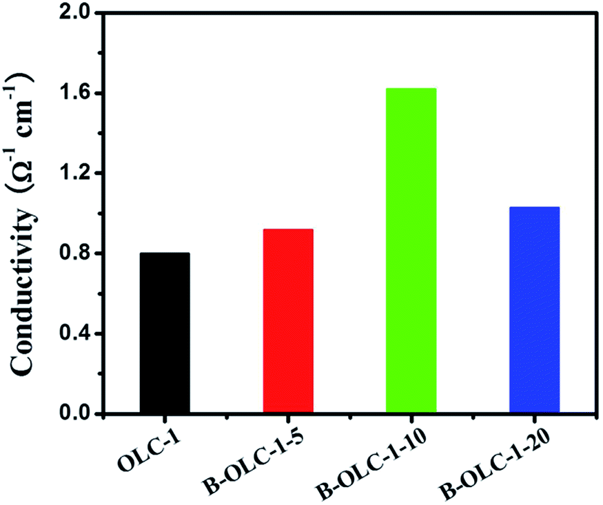
In Fig. 5, with the increase of boron content, the electrical conductivity increases from 0.8 Ω−1 cm−1 for OLC-1 to 1.62 Ω−1 cm−1 for B-OLC-1-10. However, the decreasing electrical conductivity of B-OLC-1-20 is probably due to the disruption of a fullerene-like layer structure. In a word, the introduction of boron species changes obviously the electronic properties of pristine OLC and hence it may find potential applications in the catalytic field.
 | ||
| Fig. 5 Electrical conductivity of various samples. | ||
The electrocatalytic activity of various B-OLC samples was examined in an O2-saturated 0.1 M KOH electrolyte with a rotation rate of 900 rpm at a scan rate of 5 mV s−1. As shown in Fig. 6A, the two limiting current platforms in the LSV curve of the undoped OLC catalyst indicate that the ORR catalyzed by OLC is not a four-electron process, but a typical feature of a two-electron pathway with two onset potentials of about 0.80 V and 0.48 V, where the first onset is assigned to the two-electron reduction of O2 to HO2-process. In contrast, after introducing boron species into OLC, the doped OLC catalysts exhibit a more positive onset potential and a clear sign of the direct four-electron process for the ORR, which is similar to the reference Pt/C sample (Fig. 6A). In terms of onset potential and limiting current density, both the optimum values are found on B-OLC-1-10 (0.835 V and 3.75 mA cm−2). The polarization curves of B-OLC-1-10 at different potentials and rotation speeds are shown in Fig. 6B. Interestingly, B-OLC-1-20 with the highest concentration of boron species exhibits a lower current density than B-OLC-1-10. It may be ascribed to the high-level boron that leads to the lower conductivity and a more disordered fullerene-like layer structure (Fig. 3 and 5). To get insight into the reaction mechanism of boron-doped OLC, the linear sweep voltammetry (LSV) curves of different catalysts at various electrode rotation rates ranging from 400 to 2500 rpm, and the corresponding ORR performance in the diffusion and the kinetically limited regions are evaluated by using Koutecky–Levich (K–L) plots, a typical relationship between the current density (J), kinetic current density (JK) and rotation speed (ω) as shown in Fig. 6C. All LSV curves of catalysts show a linear relationship between j−1 and ω−1/2 at a potential of 0.6 V. By calculating, a JK value of 18.5 mA cm−2 at 0.6 V on B-OLC-1-10 is obtained, and which is much higher than that of pristine and doped OLC. The detailed equation can be found in the Experimental section. Moreover, the electron-transfer number in one ORR process is 3.95 for B-OLC-1-10, revealing its perfect selectivity for the efficient four-electron-dominated ORR pathway (see Fig. 6D). This excellent electrocatalytic efficiency is much higher than that of OLC-1 (n = 2.71), B-OLC-1-5 (n = 2.96) and B-OLC-1-20 (n = 3.69), and even as well as that of the commercial Pt/C catalyst (n = 3.97–3.98).70
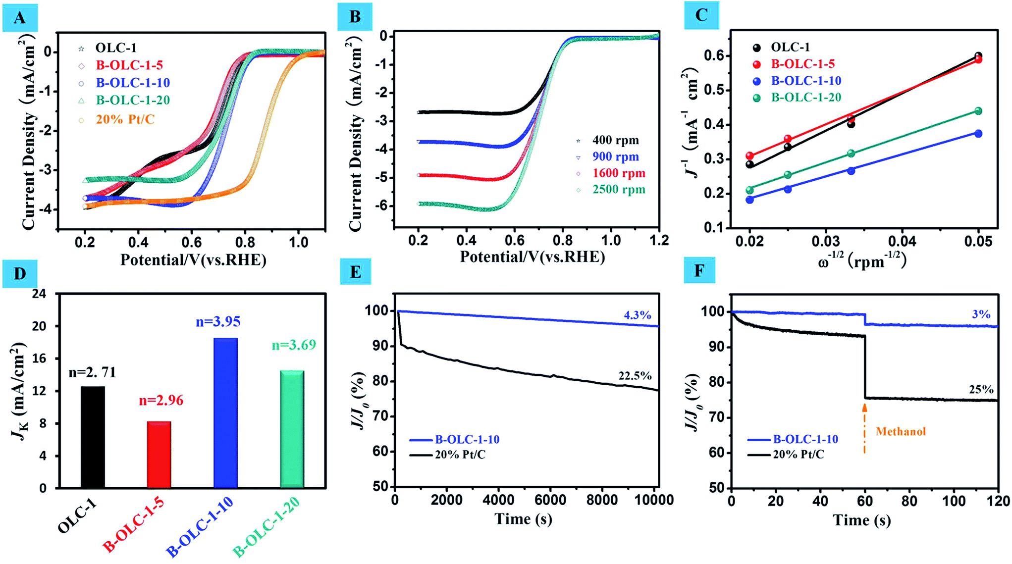 | ||
| Fig. 6 (A) Rotating disk electrode (RDE) voltammograms recorded with OLC-1, B-OLC-1-5, B-OLC-1-10, B-OLC-1-20 and Pt/C in O2-saturated 0.1 M KOH at 900 rpm, scan rate: 5 mV s−1. (B) Linear sweep voltammetry (LSV) curves of B-OLC-1-10 with a rotation rate from 400 to 2500 rpm, scan rate: 5 mV s−1. (C) Koutecky–Levich plot of J−1vs. ω−1/2 for OLC-1, B-OLC-1-5, B-OLC-1-10 and B-OLC-1-20 in 0.1 M KOH at 0.6 V. (D) Electrochemical activities given as the kinetic-limiting current density (JK) at 0.6 V for all four electrodes. (E) Durability evaluation of 20% Pt/C and B-OLC-1-10 samples for 10000 s at 0.6 V and a rotation rate of 900 rpm. (F) Chronoamperometric responses of B-OLC-1-10 and 20% Pt/C electrodes with 3 M methanol added into an O2-saturated KOH electrolyte at a constant potential of 0.6 V with a rotation rate of 900 rpm. | ||
The results in Fig. 6E indicate that the B-OLC-1-10 catalyst exhibits a much better stability than the commercial Pt/C catalyst in alkaline solution. Moreover, the tolerability of catalysts toward methanol is further investigated as can be observed in Fig. 6F. After a certain amount of methanol is added into the electrolyte, the relative current density (J/JO) of the Pt/C catalyst shows a sharp loss of 25% in activity, whereas the B-OLC-1-10 catalyst exhibits a more stable current response under the same conditions. These results clearly show that the B-OLC-1-10 as a cathode material for alkaline fuel cells has a better catalytic performance in withstanding methanol crossover and in the long-time stability compared with the commercial Pt/C catalyst.
Actually, there are some related reports on boron-doped carbon materials as electrocatalysts toward the ORR.71,72 Yang et al. demonstrated that the boron-doped CNTs exhibited excellent electrocatalytic performance for the ORR. By using DFT calculations, the authors thought that the transferred charge of incorporated boron can weaken the O–O bond of the adsorbed oxygen molecules and thus facilitate the ORR.73 Wang and co-workers proposed that the presence of boron could reduce the band gap and promote the rate of electron transfer. The atomic spin and charge densities also were considered to determine the catalytic capability of materials for ORR to some degree.74 When boron species, especially B3, were introduced into the carbon network, the nature of surface charged sites stemming from the different electronegativity of carbon and boron atoms was emphasized and hence the intrinsic relationship between the electronic properties and the corresponding catalytic performance was ignored. Moreover, theoretical calculation has always been the only tool for studying the ORR process on doped metal-free catalysts and thus lacks persuasion for the origin of the reaction mechanism. To this end, it is desired to get insight into the effects of boron on the reaction process using effective physical characterization tools. Joo et al. reported that the work function (Φ) of N-, O- and S-doped ordered mesoporous carbons (OMCs) could be measured by Kelvin probe force microscopy and found an interesting relationship between the electron transfer number and Φ toward ORR.75 Nevertheless, due to the difference of material structures and a single study for work function, these results may not provide a convincing evidence for other metal-free carbon catalysts (e.g. CNTs and graphene). In the previous section, UPS was successfully used as an effective measurement for studying the electronic properties of doped OLC catalysts. Here, in order to understand the ORR origin of doped catalysts, the correlation among the work function, valence band edge, DOS intensity and electron transfer number is studied. A linear relationship between the Φ value and electron transfer number (n) can be observed in Fig. 7A. We find that a lower Φ on the catalyst is accompanied by a higher n, implying a more efficient electrocatalytic performance under the given reaction conditions. Moreover, a good linear relationship between the valence band edge and electron transfer number (n) is also found in Fig. 7B, indicating that the introduction of boron is capable of extracting the electrons from the valence band to facilitate the reduction of oxygen molecules. Higher DOS intensity represents higher charge density around the EF (Fig. 7C). So, it is reasonable to believe that the lower work function, lower valence band edge (namely, closer to EF) and higher DOS of doped samples are accountable for the better catalytic performance. These factors are energetically favorable to activate electrons originating from the valence band of the catalyst under a low energy condition, thus leading to the facile formation of activated complexes for any potential reactions. In addition, when various low contents (0.1–0.18 at%) of BC3 species are obtained deliberately, there is no obvious difference in the work function, valence band edge and catalytic activity (onset potential) as shown in Fig. S5 and Table S2.†
 | ||
| Fig. 7 (A)–(C) The relationship graphs between the Φ, valence band edge, DOS intensity and electron transfer number, respectively. | ||
Conclusions
In summary, a class of boron-doped onion-like carbons (B-OLC) with tunable boron doping levels has been developed via a one-step approach using boric acid as the source. The incorporation of boron could effectively change the electronic structure and properties. Such novel metal-free doped nanomaterials exhibit a higher catalytic activity than pristine OLC for the ORR. Its good electrocatalytic efficiency (four-electron pathway, n = 3.95), higher tolerance for methanol, activity and stability and relatively lower cost than those of commercial Pt/C make it a promising candidate for the next generation of cost-effective ORR electrocatalysts. It is noteworthy that the work function, valence band edge and DOS measured by UPS could be correlated with the ORR activity. The lower work function of B-OLC-1-10 (4.10 eV) with a moderate boron content (2.3 at%) as compared to those of reported heteroatom-doped carbon materials makes it an interesting material for research in semiconductors, quantum dots (QDs), supercapacitors and battery in the future. We believe this insight concerning the work function, valence band edge and DOS of the doped nanocarbons can be generally used as an activity descriptor for the ORR as well as other catalytic reactions.Acknowledgements
The authors thank Dr Anmin Zheng, Junyuan Xu, Linhui Yu, Gupta Neeraj, Zhenbao Feng, Shuchang Wu, Rui Huang and Jia Wang for their kind help in this study. The authors acknowledge the financial support from MOST (2011CBA00504), NSFC of China (21133010, 51221264, 21261160487), “Strategic Priority Research Program” of the Chinese Academy of Sciences, Grant No. XDA09030103.Notes and references
- S. Iijima, J. Cryst. Growth, 1980, 50, 675 CrossRef CAS.
- H. W. Kroto and K. McKay, Nature, 1988, 331, 328 CrossRef CAS PubMed.
- D. Ugarte, Nature, 1992, 359, 707 CrossRef CAS PubMed.
- Y. Lin, X. Pan, W. Qi, B. Zhang and D. S. Su, J. Mater. Chem. A, 2014, 2, 12475 CAS.
- G. Wu, M. Nelson, S. Ma, H. Meng, G. Cui and P. K. Shen, Carbon, 2011, 49, 3972 CrossRef CAS PubMed.
- D. Pech, M. Brunet, H. Durou, P. Huang, V. Mochalin, Y. Gogotsi, P. L. Taberna and P. Simon, Nat. Nanotechnol., 2010, 5, 651 CrossRef CAS PubMed.
- Y. Wang, F. Yan, S. W. Liu, A. Y. S. Tan, H. Song, X. W. Sun and H. Y. Yang, J. Mater. Chem. A, 2013, 1, 5212 CAS.
- P. Simon and Y. Gogotsi, Nat. Mater., 2008, 7, 845 CrossRef CAS PubMed.
- D. Su, N. I. Maksimova, G. Mestl, V. L. Kuznetsov, V. Keller, R. Schlögl and N. Keller, Carbon, 2007, 45, 2145 CrossRef CAS PubMed.
- N. Matsumoto, P. L. Joly, H. Kinoshita and N. Ohmae, Diamond Relat. Mater., 2007, 16, 1227 CrossRef CAS PubMed.
- O. Shenderova, V. Grishko, G. Cunningham, S. Moseenkov, G. McGuire and V. Kuznetsov, Diamond Relat. Mater., 2008, 17, 462 CrossRef CAS PubMed.
- A. V. Gubarevich, J. Kitamura, S. Usuba, H. Yokoi, Y. Kakudate and O. Odawara, Carbon, 2003, 41, 2601 CrossRef CAS.
- A. Inoue, T. Seto and Y. Otani, Carbon, 2012, 50, 1116 CrossRef CAS PubMed.
- C. Zhang, J. Li, C. Shi, E. Liu, X. Du, W. Feng and N. Zhao, Carbon, 2011, 49, 1151 CrossRef CAS PubMed.
- R. Borgohain, J. Yang, J. P. Selegue and D. Y. Kim, Carbon, 2014, 66, 272 CrossRef CAS PubMed.
- K. Bogdanov, A. Fedorov, V. Osipov, T. Enoki, K. Takai, T. Hayashi, V. Ermakov, S. Moshkalev and A. Baranov, Carbon, 2014, 73, 78 CrossRef CAS PubMed.
- U. N. Maiti, W. J. Lee, J. M. Lee, Y. Oh, J. Y. Kim, J. E. Kim, J. Shim, T. H. Han and S. O. Kim, Adv. Mater., 2014, 26, 40 CrossRef CAS PubMed.
- D. W. Wang and D. Su, Energy Environ. Sci., 2014, 7, 576 CAS.
- Y. Lin and D. S. Su, ACS Nano, 2014, 8, 7823 CrossRef CAS PubMed.
- Y. A. Kim, K. Fujisawa, H. Muramatsu, T. Hayashi, M. Endo, T. Fujimori, K. Kaneko, M. Terrones, J. Behrends, A. Eckmann, C. Casiraghi, K. S. Novoselov, R. Saito and M. S. Dresselhaus, ACS Nano, 2012, 6, 6293 CrossRef CAS PubMed.
- Z. H. Sheng, H. L. Gao, W. J. Bao, F. B. Wang and X. H. Xia, J. Mater. Chem., 2012, 22, 390 RSC.
- H. Wang, Y. Zhou, D. Wu, L. Liao, S. Zhao, H. Peng and Z. Liu, Small, 2013, 9, 1316 CrossRef CAS PubMed.
- X. Li, L. Fan, Z. Li, K. Wang, M. Zhong, J. Wei, D. Wu and H. Zhu, Adv. Energy Mater., 2012, 2, 425 CrossRef CAS PubMed.
- J. Han, L. L. Zhang, S. Lee, J. Oh, K. S. Lee, J. R. Potts, J. Ji, X. Zhao, R. S. Ruoff and S. Park, ACS Nano, 2012, 7, 19 CrossRef PubMed.
- Z. S. Wu, W. Ren, L. Xu, F. Li and H. M. Cheng, ACS Nano, 2011, 5, 5463 CrossRef CAS PubMed.
- J. M. Lee, J. S. Park, S. H. Lee, H. Kim, S. Yoo and S. O. Kim, Adv. Mater., 2011, 23, 629 CrossRef CAS PubMed.
- A. S. Aricò, P. Bruce, B. Scrosati, J. M. Tarascon and W. van Schalkwijk, Nat. Mater., 2005, 4, 366 CrossRef PubMed.
- M. Kendig, M. Hon and L. Warren, Prog. Org. Coat., 2003, 47, 183 CrossRef CAS.
- J. Yang, S. Deng, J. Lei, H. Ju and S. Gunasekaran, Biosens. Bioelectron., 2011, 29, 159 CrossRef CAS PubMed.
- S. Wang, E. Iyyamperumal, A. Roy, Y. Xue, D. Yu and L. Dai, Angew. Chem., Int. Ed., 2011, 50, 11756 CrossRef CAS PubMed.
- L. Qu, Y. Liu, J. B. Baek and L. Dai, ACS Nano, 2010, 4, 1321 CrossRef CAS PubMed.
- J. Liang, Y. Jiao, M. Jaroniec and S. Z. Qiao, Angew. Chem., Int. Ed., 2012, 51, 11496 CrossRef CAS PubMed.
- G. Tian, M. Zhao, D. Yu, X. Kong, J. Huang, Q. Zhang and F. Wei, Small, 2014, 10, 2251 CrossRef CAS PubMed.
- T. Sharifi, G. Hu, X. Jia and T. Wågberg, ACS Nano, 2012, 6, 8904 CrossRef CAS PubMed.
- Y. Zheng, Y. Jiao, L. Ge, M. Jaroniec and S. Z. Qiao, Angew. Chem., 2013, 125, 3192 CrossRef PubMed.
- J. Zhang, J. Li, Z. Wang, X. Wang, W. Feng, W. Zheng, W. Cao and P. Hu, Chem. Mater., 2014, 26, 2460 CrossRef CAS.
- H. Fei, R. Ye, G. Ye, Y. Gong, Z. Peng, X. Fan, E. L. G. Samuel, P. M. Ajayan and J. M. Tour, ACS Nano, 2014, 8, 10837 CrossRef CAS PubMed.
- Z. Yang, Z. Yao, G. Li, G. Fang, H. Nie, Z. Liu, X. Zhou, X. Chen and S. Huang, ACS Nano, 2011, 6, 205 CrossRef CAS.
- D. Wang and D. Su, Energy Environ. Sci., 2014, 7, 576 CAS.
- N. Rodriguez and R. Baker, J. Mater. Res., 1993, 8, 1886 CrossRef CAS.
- T. Shirasaki, A. Derré, M. Ménétrier, A. Tressaud and S. Flandrois, Carbon, 2000, 38, 1461 CrossRef CAS.
- S. Jacques, A. Guette, X. Bourrat, F. Langlais, C. Guimon and C. Labrugere, Carbon, 1996, 34, 1135 CrossRef CAS.
- L. Panchakarla, A. Govindaraj and C. Rao, ACS Nano, 2007, 1, 494 CrossRef CAS PubMed.
- R. Wang, X. Sun, B. Zhang, X. Sun and D. S. Su, Chem.–Eur. J., 2014, 20, 6324 CrossRef CAS PubMed.
- R. F. Egerton, Chapter 1-An Introduction to EELS. Electron Energy-loss Spectroscopy in the Electron Microscope, Plenum Press, New York, 3rd edn, 1996 Search PubMed.
- S. Waidmann, M. Knupfer, J. Fink, B. Kleinsorge and J. Robertson, Diamond Relat. Mater., 2000, 9, 722 CrossRef CAS.
- X. Liu, H. Romero, H. Gutierrez, K. Adu and P. Eklund, Nano Lett., 2008, 8, 2613 CrossRef CAS PubMed.
- J. Robin, J. Mater. Chem., 2000, 10, 1425 RSC.
- M. S. Dresselhaus, G. Dresselhaus, R. Saito and A. Jorio, Phys. Rep., 2005, 409, 47 CrossRef PubMed.
- A. C. Ferrari and J. Robertson, Phys. Rev. B: Condens. Matter Mater. Phys., 2000, 61, 14095 CrossRef CAS.
- C. Thomsen and S. Reich, Phys. Rev. Lett., 2000, 85, 5214 CrossRef CAS.
- J. Jiang, R. Saito, Ge. G. Samsonidze, A. Jorio, S. G. Chou, G. Dresselhaus and M. S. Dresselhaus, Phys. Rev. B: Condens. Matter Mater. Phys., 2007, 75, 035407 CrossRef.
- M. S. Dresselhaus, A. Jorio, M. Hofmann, G. Dresselhaus and R. Saito, Nano Lett., 2010, 10, 751 CrossRef CAS PubMed.
- A. Das, S. Pisana, B. Chakraborty, S. Piscanec, S. K. Saha, U. V. Waghmare, K. S. Novoselov, H. R. Krishnamurthy, A. K. Geim and A. C. Ferrari, Nat. Nanotechnol., 2008, 3, 210 CrossRef CAS PubMed.
- M. Endo, C. Kim, T. Karaki, T. Tamaki, Y. Nishimura, M. J. Matthews, S. D. M. Brown and M. S. Dresselhaus, Phys. Rev. B: Condens. Matter Mater. Phys., 1998, 58, 8991 CrossRef CAS.
- A. C. Ferrari, Solid State Commun., 2007, 143, 47 CrossRef CAS PubMed.
- M. Calandra and F. Mauri, Phys. Rev. B: Condens. Matter Mater. Phys., 2007, 76, 205411 CrossRef.
- C. Casiraghi, Phys. Rev. B: Condens. Matter Mater. Phys., 2009, 80, 233407 CrossRef.
- A. C. Ferrari and D. M. Basko, Nat. Nanotechnol., 2013, 8, 235 CrossRef CAS PubMed.
- R. Saito, A. Grüneis, G. G. Samsonidze, V. Brar, G. Dresselhaus, M. Dresselhaus, A. Jorio, L. Cançado, C. Fantini and M. Pimenta, New J. Phys., 2003, 5, 157 CrossRef.
- M. Huang, H. Yan, C. Chen, D. Song, T. F. Heinz and J. Hone, Proc. Natl. Acad. Sci. U. S. A., 2009, 106, 7304 CrossRef CAS PubMed.
- C. Attaccalite, L. Wirtz, M. Lazzeri, F. Mauri and A. Rubio, Nano Lett., 2010, 10, 1172 CrossRef CAS PubMed.
- Z. Luo, S. Lim, Z. Tian, J. Shang, L. Lai, B. MacDonald, C. Fu, Z. Shen, T. Yu and J. Lin, J. Mater. Chem., 2011, 21, 8038 RSC.
- J. Gebhardt, R. Koch, W. Zhao, O. Höfert, K. Gotterbarm, S. Mammadov, C. Papp, A. Görling, H. P. Steinrück and T. Seyller, Phys. Rev. B: Condens. Matter Mater. Phys., 2013, 87, 155437 CrossRef.
- S. Suzuki, C. Bower, Y. Watanabe and O. Zhou, Appl. Phys. Lett., 2000, 76, 4007 CrossRef CAS PubMed.
- D. Marchand, C. Fretigny, M. Lagues, F. Batallan, C. Simon, I. Rosenman and R. Pinchaux, Phys. Rev. B: Condens. Matter Mater. Phys., 1984, 30, 4788 CrossRef CAS.
- J. W. Wilder, L. C. Venema, A. G. Rinzler, R. E. Smalley and C. Dekker, Nature, 1998, 391, 59 CrossRef.
- F. McFeely, S. Kowalczyk, L. Ley, R. Cavell, R. Pollak and D. Shirley, Phys. Rev. B: Condens. Matter Mater. Phys., 1974, 9, 5268 CrossRef CAS.
- M. Shiraishi and M. Ata, Carbon, 2001, 39, 1913 CrossRef CAS.
- K. Parvez, S. Yang, Y. Hernandez, A. Winter, A. Turchanin, X. Feng and K. Müllen, ACS Nano, 2012, 6, 9541 CrossRef CAS PubMed.
- Y. Jiao, Y. Zheng, M. Jaroniec and S. Z. Qiao, J. Am. Chem. Soc., 2014, 136, 4394 CrossRef CAS PubMed.
- E. Pourazadi, E. Haque, W. Zhang, A. T. Harris and A. I. Minett, Chem. Commun., 2013, 49, 11068 RSC.
- L. Yang, S. Jiang, Y. Zhao, L. Zhu, S. Chen, X. Wang, Q. Wu, J. Ma, Y. Ma and Z. Hu, Angew. Chem., 2011, 123, 7270 CrossRef PubMed.
- S. Wang, L. Zhang, Z. Xia, A. Roy, D. W. Chang, J. B. Baek and L. Dai, Angew. Chem., Int. Ed., 2012, 51, 4209 CrossRef CAS PubMed.
- J. Y. Cheon, J. H. Kim, J. H. Kim, K. C. Goddeti, J. Y. Park and S. H. Joo, J. Am. Chem. Soc., 2014, 136, 8875 CrossRef CAS PubMed.
Footnote |
| † Electronic supplementary information (ESI) available: The materials of additional data and figures about the BET analysis, XPS spectra, TG, and XRD for various samples. See DOI: 10.1039/c5ta03141a |
| This journal is © The Royal Society of Chemistry 2015 |