
 Open Access Article
 This Open Access Article is licensed under a
 Creative Commons Attribution 3.0 Unported Licence
Heat treatment of ZnO nanoparticles: new methods to achieve high-purity nanoparticles for high-voltage applications†
A. M.
Pourrahimi
a,
D.
Liu
a,
V.
Ström
b,
M. S.
Hedenqvist
a,
R. T.
Olsson
a and
U. W.
Gedde
*a
aKTH Royal Institute of Technology, School of Chemical Science and Engineering, Fibre and Polymer Technology, SE-100 44 Stockholm, Sweden. E-mail: gedde@kth.se; Fax: +46 8 208856; Tel: +46 8 790 7640
bKTH Royal Institute of Technology, School of Industrial Engineering and Management, Material Science and Engineering, SE-100 44 Stockholm, Sweden
First published on 16th July 2015
Abstract
Novel methods based on orienting and coating of ZnO nanoparticles were studied in order to obtain uniform, nano-sized and ultra-pure ZnO grains/particles after heat treatment. A 1 nm zinc-hydroxy-salt complex layer on the nanoparticle surfaces was revealed by thermogravimetry and infrared spectroscopy. This ‘phase’ gradually decomposed into ZnO during the heat treatment while sintering occurred above 600 °C, as revealed by scanning- and transmission-electron microscopy. The c-axis alignment of the nanoparticles provided smaller pores than those associated with non-oriented nanoparticles, presenting the means to obtain high-density ceramics. The orientation resulted in a smaller grain size after heat treatment than that of the nonaligned nanoparticles. Another method that involved three steps – silane coating, heat treatment and silica layer etching – was used to remove the ionic species from the nanoparticle surface while preserving its hydroxylated surface. These ultra-pure nanoparticles are expected to be key components in the development of HVDC insulation polyethylene nanocomposites.
1. Introduction
Renewable electric power generation is a rapidly expanding field, and there is a need to increase the long-distance transmission capacity with lower energy losses. The most feasible solution is underground and submarine high-voltage direct current (HVDC) cables with a maximum anticipated voltage of 1 MV by 2030.1 Extruded HVDC cables insulated with crosslinked polyethylene are commercially available for use up to 525 kV.2 One strategy to enhance the insulating performance of polyethylene is by the incorporation of dispersed metal oxide (e.g. ZnO) nanoparticles at very low concentrations. The nanoparticles adsorb ionic/polar species and suppress space charge accumulation in the insulating polymer matrix and thus reduce the conductivity in a high electric field.3–5 The challenge in the development of nanocomposites with ultra-low electrical conductivity is to find highly pure nanoparticles without conducting counter-ions on the particle surfaces, but, it is essential that nanoparticles are functionalized with hydroxide groups in order to allow further coating chemistry to be applied. High-purity ZnO is essential not only for electrical insulations but also for varistor ceramics in electronic applications.Different methods have been used to synthesize ZnO nanoparticles among which water-based precipitation at low temperatures is versatile, inexpensive and gives a high yield,6 and the surfaces of the nanoparticles prepared by this method have a high concentration of zinc hydroxide.6–10 The hydroxide groups are stabilized by the anions remaining from the zinc salt precursors which form quasi-crystalline zinc hydroxy salt (ZHS)11–14 with a composition depending on the zinc salt precursor anion. It has been suggested that the ZHS species with acetate anions create an amphiphilic capping layer around primary ZnO nanoparticles, and that they provide steric repulsion and colloidal stability among the particles during and after the aqueous precipitation.6,15,16 In contrast, nitrate counter-ions could not form a capping layer, the result being extensive self-assembly of the primary nanoparticles along the c-axis with sub-micron flower-shaped morphologies.6 The ZHS phase adsorbs impurities and forms hard aggregates of the nanoparticles in polymer nanocomposites.7 The ZHS decomposes due to the release of water and ionic species into pure ZnO during high-temperature annealing.11,13
Heat treatment is thus efficient in transforming the nanoparticles with a surface ZHS phase into pure ZnO, but the disadvantage is the accompanying undesirable nanoparticle sintering leading to larger particles/grains.17 A higher breakdown voltage of nanocomposites with ultra-low electrical conductivity was obtained by decreasing the particle size from μm to nm.18 With regard to varistor applications, electrical characteristics such as the resistivity and dielectric properties of ZnO ceramics can be tuned by controlling the sintering process.19–29 The grain boundaries in the varistors provide a high charge barrier compared to that of the conductive ZnO bulk grains, and hence the breakdown voltage depends on the number of grain boundaries per unit volume.28,29 As the grain size decreases, the number of grain boundaries increases and this leads to an increase in breakdown voltage.30 Meng et al.27 obtained small-grain ultra-dense ZnO ceramics by a specific heat treatment with a favourable electrical performance with high breakdown strength, excellent nonlinear coefficient and low leakage current.
Different methods have been used to obtain nano-sized ZnO particles/grains after the heat treatment: sintering under different atmospheres,31–33 two-step sintering,26,30,34–36 microwave sintering,37 spark plasma sintering,38 addition of dopants,28,39,40 silica coating17,27 and sintering using oriented particles.29 Spark plasma sintering yields dense and fine-grained ceramics with a rapid sintering rate, but the method is not useful for industrial applications.36 A two-step-sintering process was developed with the purpose of obtaining large quantities of nano-sized grains. During the first step, the relative density is increased by treatment at temperatures above 900 °C by the destabilisation of pores.35 The second step is carried out at temperatures below 600 °C with the purpose of minimizing the grain growth. The relatively low final density and the long sintering times required are drawbacks compared to the conventional one-step-sintering.41,42 The silica coating of the particles retained the initial large surface area, and the hydroxy salt complex on the particle surfaces was transformed into pure oxide by the heat treatment.
This paper presents two new strategies to achieve high purity, fine and nano-sized ZnO particles/grains during the heat treatment above 600 °C intended for high-voltage applications. In both strategies, the zinc hydroxy salt phase as a surface defect was transformed to pure ZnO. One strategy was based on silane coating of ZnO nanoparticles, heat treatment and finally removal of the silica layer. The processed particles had a zinc hydroxide surface without the presence of associated ionic species while preserving their nano-sizes. Another strategy was to increase the density of ZnO ceramics by orienting the nanoparticles and reducing the inter-particle pore size. A positive effect of nanoparticle orientation is the possible minimization of grain growth accompanying the heat treatment. It is shown that a single-step-sintering process can yield uniform, nano-sized and ultra-pure ZnO grains.
2. Experimental
2.1. Materials
Zinc nitrate hexahydrate (Zn(NO3)2·6H2O, ≥98 wt%, Sigma-Aldrich), zinc acetate dihydrate (Zn(CH3COO)2·2H2O, ≥99wt%, Sigma-Aldrich), sodium hydroxide (≥98 wt%, Sigma-Aldrich), octadecyl trimethoxy silane (OTMS, ≥90 wt%, Sigma-Aldrich), ammonia hydroxide (25 wt%, Sigma-Aldrich), 2-propanol (≥99.5 wt%, VWR), ethanol (≥96 wt%, VWR) and potassium bromide (KBr, ≥98 wt%, FTIR grade, Sigma-Aldrich) were used as received. High resistivity Milli-Q water (18.2 MΩ cm at 25 °C) was used in all the aqueous reactions.2.2. Synthesis of ZnO nanoparticles
2.3. Heat treatment of zinc oxide particles
The ZnO particles were heat-treated from 23 °C to 600 °C with a heating rate of 10 °C min−1 and held at 600 °C for 1 h in a muffle furnace (ML Furnaces) with ambient air. The heat-treated particles were designated as ZA-8g T and ZN-8g T. For the grain growth study, pristine and OTMS-coated ZA-8g were heat-treated in a Mettler Toledo TG/DSC 1 at different temperatures (600, 800 and 1000 °C) and for different periods of time (10, 30, 60, 120 and 240 min) in dry nitrogen with a flow rate of 50 mL min−1.2.4. Alkaline etching
After heat treatment, the 0.4 g OTMS-coated ZA-8g nanoparticles were dispersed in 50 mL of 1 M NaOH aqueous solution under ultrasonication for 30 min in order to remove the silica shell. The applied energy per volume (weight) of the nanoparticle material in the suspension was estimated to be ca. 4.8 kJ per 50 mL of particles (0.4 g). The etched ZnO nanoparticles were purified thrice in ultrasonicated Milli-Q water.2.5. Particle characterisation
A field emission scanning electron microscope (SEM; Hitachi S-4800) and a transmission electron microscope (TEM; Hitachi HT7700) were used to assess the habit and size distributions of the ZnO nanoparticles. For SEM: powder samples were coated with a thin conductive layer of Pt/Pd (60/40) for 20 s of sputtering using a current of 80 mA in a Cressington 208 HR. The samples were examined in the microscope with an acceleration voltage of 5 kV and a current of 10 μA. The size distribution of the nanoparticles was obtained by manually measuring 600 particles using ImageJ (National Institute of Health, Maryland, USA). For TEM: the particles were deposited on 400 mesh copper grids from a suspension of pure ethanol containing a particle concentration of 0.45 ± 0.05 g L−1. The samples were dried and examined in the microscope operating at an acceleration voltage of 100 kV.The Brunauer–Emmett–Teller (BET) method based on nitrogen adsorption/desorption with a Micromeritics ASAP 2000 at 77 K was used to determine the specific surface area and pore size distribution.
X-ray diffractograms of the powder samples were recorded at room temperature using a PANalytical X'pert Pro MPD diffractometer with a Cu-Kα source (wavelength = 1.54178 Å) using a 2θ step size of 0.017°. The crystal size was obtained from the Scherrer equation:
 | (1) |
Thermogravimetry (TG) was carried out in a Mettler Toledo TG/DSC 1. Powder samples weighing 5 ± 1 mg were placed in 70 μL alumina crucibles and heated from 30 to 800 °C at a rate of 10 °C min−1 in dry nitrogen with a flow rate of 50 mL min−1.
Infrared spectra of the nanoparticle samples before and after heat treatment were recorded with a Perkin-Elmer Spectrum 2000 FTIR spectrometer and analysed with Perkin-Elmer Spectrum software (Norwalk, CT, USA). The samples were prepared by mixing 3 mg of particles and 300 mg of ground KBr and pressing the mixture under a load of 100 kN for 1 min in a die to form a pellet. The wavenumber range used was 450 cm−1 to 4000 cm−1 with a spectral resolution of 4 cm−1. Each spectrum was based on 32 scans.
Photoluminescence (PL) emission measurements were performed at 23 °C in a Perkin-Elmer LS55 instrument equipped with a Xe lamp. An aqueous particle suspension with a particle concentration of 2.67 g L−1 was placed in a quartz cuvette with an inner cross-section of 10 × 10 mm2. The excitation wavelength was 290 nm, and both the excitation and emission slits had a width of 5 nm.
X-ray photoelectron spectroscopy (XPS) spectra were collected with a Kratos Axis Ultra DLD electron spectrometer using a monochromatic Al Kα source operating at 150 W. An analyser pass energy of 160 eV for acquiring wide spectra and a pass energy of 20 eV for individual photoelectron lines were used. The surface potential was stabilized by using the spectrometer charge neutralization system. The binding energy (BE) scale was referenced to the C 1s line of aliphatic carbon, set at 285.0 eV. The spectra were processed with the Kratos software. Powder samples for the analysis were pressed into a pellet directly on a sample holder using a Ni spatula.
3. Results and discussion
3.1. Morphology of ZnO particles
Fig. 1a and b show transmission electron micrographs of the ZnO particles synthesized from zinc acetate and zinc nitrate precursors, respectively. The zinc acetate precursor yielded separate and randomly oriented nanoparticles with an average size of ca. 25 nm, whereas zinc nitrate yielded submicron flower-shaped particles with a symmetrical habit. These submicron particles consisted of c-axis oriented primary nanoparticles along each petal (spike) director, as shown by black arrows (Fig. 1b). This important finding was confirmed by electron diffraction and high resolution TEM data presented elsewhere6 (see also ESI, Fig. S1†). Oliveira et al.43 observed the orientation of nanoparticles inside flower-shaped particles in a kinetic study of the reaction between zinc nitrate and sodium hydroxide. It was reported in another paper that only a few nanoparticles deviated from perfect alignment as a result of lattice imperfection, and improper stacking in contacting areas among the primary nanoparticles44 inside the flower-shaped particles.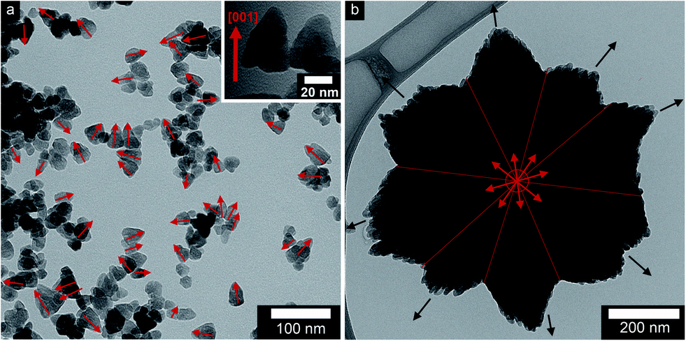 | ||
| Fig. 1 Transmission electron micrographs of ZnO nanoparticles: (a) non-oriented (ZA-8g) and (b) oriented (ZN-8g) (red and black arrows show the c-axis and director). | ||
Fig. 2 presents scanning electron micrographs of non-oriented and aligned ZnO nanoparticles, before and after heat treatment at 600 °C, together with the particle size distributions. The heat treatment smoothed the niched surface of both nano and submicron particles and the nanoparticles merged into larger grains. The nanoparticles doubled in size while the submicron particles decreased from ca. 550 to 520 nm during the heat treatment (Table 1). Mouzon et al.45 modelled the transient structure during sintering. According to their model, necks and grain boundaries between the primary particles were formed and the sharp edges of the nanoparticles curved due to a process referred to as the spheroidization process.45 Gu et al.46 removed the terrace-like surface (shown in the inset of Fig. 2a) of the ZnO particles by heat treatment at 1100 °C in air and obtained nanoparticles with atomically smooth Zn- and O-terminated surfaces. After the grain boundary had formed, the smaller particles were consumed by the larger particles by an Ostwald ripening process (sublimation and recrystallization on larger particles).33,47 These steps are shown in Fig. 2b (the inset micrograph). The fact that the oriented nanoparticle aggregates decreased in size by 6% on heat treatment suggested that the sintering of the oriented nanoparticles increased the density by 20% (assuming that the bulk density is proportional to the reciprocal of the oriented nanoparticle aggregate volume) by the elimination of inter-particle pores. These pores are further discussed in Section 3.3.
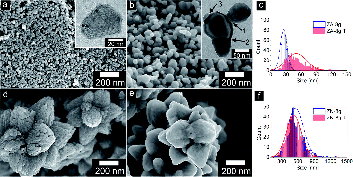 | ||
| Fig. 2 Scanning electron micrographs of ZnO particles before and after heat treatment at 600 °C in air (a) ZA-8g, the inset shows the terrace-like surface of a ZnO nanoparticle from top view; (b) ZA-8g T, arrows marked 1, 2 and 3 show the sintering steps as neck formation, grain boundary formation and Ostwald ripening, respectively; (d) ZN-8g; (e) ZN-8g T; (c) and (f) particle size distribution. | ||
| Sample | Metal salt precursor | SEM particle size (nm) | BET surface area (m2 g−1) | Crystal sizea (nm) | Crystal size ratio (Dc-axis/Da-axis)b | Volume of unit-cell (Å3) |
|---|---|---|---|---|---|---|
a Crystal size was calculated based on the X-ray diffractogram peak at 36° corresponding to the (101) crystal plane.
b The ratio 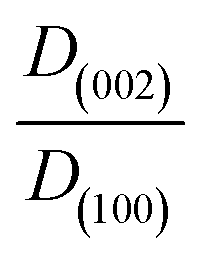 is obtained by using the Scherrer equation (eqn (1)). is obtained by using the Scherrer equation (eqn (1)).
|
||||||
| ZA-8g | Zn(O2CCH3)2·2H2O | 25 ± 6 | 33.6 | 22 | 1.19 | 47.9 |
| ZA-8g T | Zn(O2CCH3)2·2H2O | 50 ± 20 | 11.8 | 34 | 0.95 | 47.8 |
| ZN-8g | Zn(NO3)2·6H2O | 555 ± 146 | 12.6 | 22 | 1.47 | 47.9 |
| ZN-8g T | Zn(NO3)2·6H2O | 524 ± 137 | 3.8 | 25 | 1.00 | 47.8 |
3.2. Thermal decomposition of zinc hydroxy salt (ZHS) into ZnO
Fig. 3 (upper diagram) shows the normalized mass plotted as a function of temperature for non-oriented and oriented nanoparticle systems. The total mass losses of less than 3% in the thermograms were divided into a low (30–185 °C) and a high temperature (185–800 °C) region. The former was assigned to the removal of loosely bound water on the nanoparticle surface, and the latter was attributed to the decomposition of ZHS into ZnO.11 The greater mass loss of the non-oriented nanoparticle system (ZA-8g) in the low temperature region was due to the larger surface area (33.6 m2 g−1) accessible for water sorption in this sample compared to the sample based on the densely packed oriented nanoparticles (ZN-8g) (12.6 m2 g−1) (Table 1). The mass loss in the high temperature region was 2.5% regardless of the nanoparticle orientation (Table 1), which suggests that the hydroxyl group concentration on the nanoparticles was the same in the two systems (ZA-8g and ZN-8g).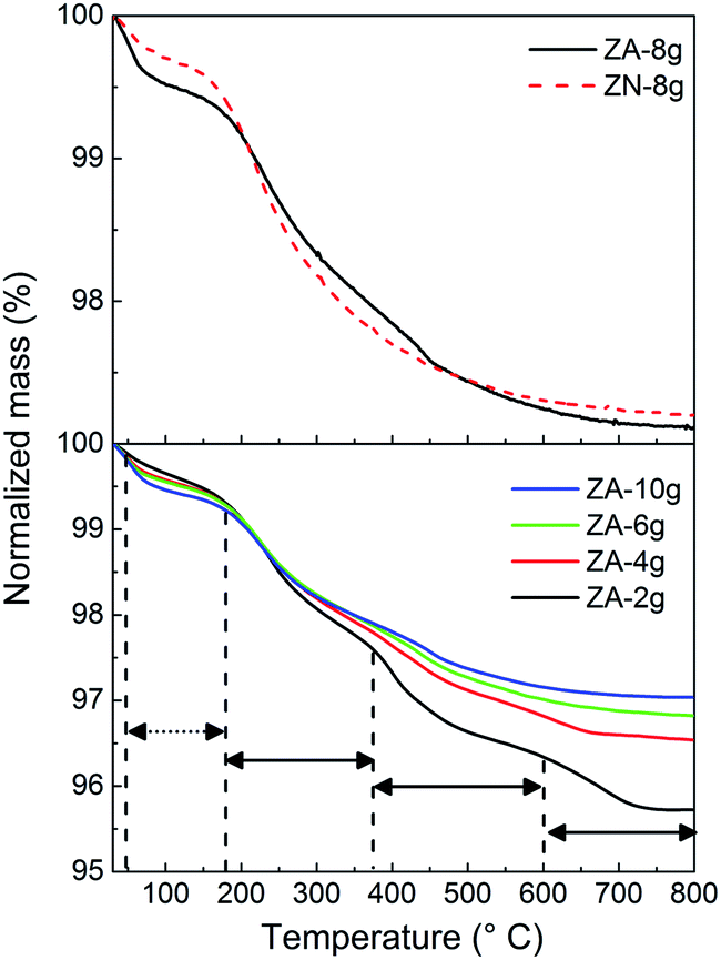 | ||
| Fig. 3 Normalized mass plotted as a function of temperature as revealed by TG for the different ZnO particles prepared. Dashed and solid arrows indicate the low and high temperature ranges. | ||
It was reported that the ZHS phase formed as an intermediate complex during ZnO particle precipitation.48,49 For the acetate system, the amount of ZHS composition increased with a decrease in the concentration of zinc acetate solution during the aqueous precipitation of ZnO particles.49 In order to clarify the decomposition of ZHS species on the surface of ZnO particles, TG was carried out on samples based on non-oriented ZnO nanoparticles synthesized using different concentrations of the zinc acetate precursor (Fig. 3 (lower diagram)). The mass loss curves showed four distinct regions of mass loss in the case of the ZA-samples: 20–185 °C (loosely bound water), 185–380 °C, 380–600 °C and 600–800 °C (decomposition of ZHS into ZnO). Moezzi et al.11 reported that acetone, acetic acid, acetic anhydride and water evaporated in three steps at high temperatures during the thermal decomposition of ZHS into ZnO. The different products indicated that the ZHS structure was Zn5(OH)8(C2H3O2−)2·2H2O.8,11 The proposed chemical reaction for the decomposition of ZHS into ZnO is:
| Zn5(OH)8(C2H3O2−)2·2H2O (s) → 5ZnO (s) + 2H(C2H3O2−) (g) + 5H2O (g) | (2) |
According to the stoichiometry of this decomposition reaction, the measured high-temperature (>185 °C) mass loss of 2.5% from ZA-8g indicated that 7.3% of the ZnO nanoparticles were covered by ZHS. It was assumed that the ZHS phase was uniformly distributed over the exterior surface of the spherical ZnO nanoparticles. The calculated ZHS thickness on the ZnO nanoparticle surface was close to 1 nm. The expected thickness of the ZHS layer ranges between 1 and 1.6 nm depending on the size of the anions and their interaction with the zinc hydroxide layer.50 A thickness of 1 nm corresponds to one atomic layer of ZHS on the surface of a ZnO nanoparticle.
Fig. 4a shows the IR spectra of the non-oriented and oriented nanoparticle samples before (continuous line) and after (broken line) heat treatment in air at 600 °C. The absorbance band at 450–600 cm−1 is assigned to the Zn–O stretching and the absorbance band at 880 cm−1 originates from the stretching vibration of Zn–OH.51 Two different interaction types of OH groups on the surface of ZnO particles have been reported:52 (i) the 3000–3650 cm−1 band is due to the reversible dissociative adsorption of hydrogen on both O and Zn sites; (ii) the 1610–1630 cm−1 band is due to chemisorbed water. The broad peak at ca. 1365 cm−1 corresponds to the nitrate anion vibration, and the peak at ca. 1635 cm−1 shows the δ-vibration of interlayer water for the ZHS structure,50 which were found in the spectrum of ZN-8g. The two broad absorbance peaks at 1380–1390−1 cm and 1480–1510 cm−1 are assigned to the C–O and C![[double bond, length as m-dash]](https://www.rsc.org/images/entities/char_e001.gif) O stretching vibrations in the acetate anion,50,53 which were present in the spectrum of ZA-8g. The intensities of the nitrate and acetate peaks around 1500 cm−1 were slightly weak due to their low concentrations; however the presence of acetate groups was confirmed by the XPS experimental results described in Section 3.4. The high concentration of acetate anions in ZA-2g, as indicated by TG (Fig. 3b), was also confirmed by IR; the three intensities assigned to C–H stretching (2850–2990 cm−1) were the highest for this particular sample (Fig. 4b). The heat-treated samples showed none of the absorbance bands assigned to the ZHS structure (Fig. 4a). The IR spectrum of the heat-treated nanoparticles after exposure to humid air (100% RH for 3 h) showed a very small amount of either chemi- or physi-sorbed water or zinc hydroxide (Fig. 4c). This was proof that the heat-treated ZnO nanoparticles retained their structures even after extended exposure to moisture.
O stretching vibrations in the acetate anion,50,53 which were present in the spectrum of ZA-8g. The intensities of the nitrate and acetate peaks around 1500 cm−1 were slightly weak due to their low concentrations; however the presence of acetate groups was confirmed by the XPS experimental results described in Section 3.4. The high concentration of acetate anions in ZA-2g, as indicated by TG (Fig. 3b), was also confirmed by IR; the three intensities assigned to C–H stretching (2850–2990 cm−1) were the highest for this particular sample (Fig. 4b). The heat-treated samples showed none of the absorbance bands assigned to the ZHS structure (Fig. 4a). The IR spectrum of the heat-treated nanoparticles after exposure to humid air (100% RH for 3 h) showed a very small amount of either chemi- or physi-sorbed water or zinc hydroxide (Fig. 4c). This was proof that the heat-treated ZnO nanoparticles retained their structures even after extended exposure to moisture.
 | ||
| Fig. 4 IR spectra of ZnO particles (a) synthesized from nitrate and acetate zinc salt precursors in 8 g batches before (continuous curve) and after (dotted curve) heat treatment at 600 °C in air, (b) synthesized from different concentrations of the zinc acetate precursor, and (c) heat-treated nanoparticles after exposure to humid air. | ||
3.3. Sintering characteristics of oriented ZnO nanoparticles
Fig. 5 presents nitrogen desorption/adsorption isotherms together with the corresponding Barret–Joyner–Halenda (BJH) pore size distributions (insert graphs) of the ZnO particles before and after heat treatment in air at 600 °C. All the samples obeyed the isotherm type III with hysteresis loops of different sizes according to the IUPAC classification.54 The samples based on non-oriented nanoparticles prior to heat treatment exhibited a small H1 hysteresis loop, suggesting nanoparticles with a uniform size. A large H3 hysteresis loop was observed in the case of the sample with oriented nanoparticles, suggesting that the pores had a slit shape. The pores in solid materials are classified as intra-particle, inter-particle and inter-aggregate based on the pore size.55 Since the nanoparticles in both systems were synthesized as mono-domain crystals,6 they did not show any intra-particle porosity. The non-oriented nanoparticles showed a small volume of inter-particle pores (2 to 4 nm), and a large volume of inter-aggregation pores (5 to 50 nm). The oriented nanoparticle system showed mainly inter-particle pores (3.5 nm) among the primary nanoparticles inside the submicron flower-shaped particles. The inter-particle pores in the oriented nanoparticle system were entirely removed by heat treatment, whereas the sample based on non-oriented nanoparticles retained its inter-particle pores (Fig. 5c and d (the inset graph)). This demonstrates the ultra-dense structure of heat-treated oriented nanoparticles.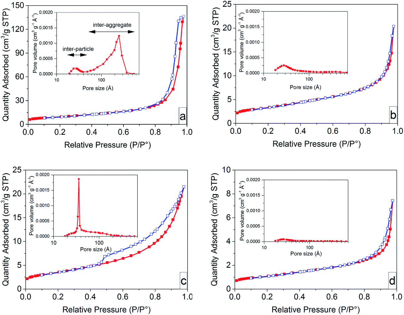 | ||
| Fig. 5 Nitrogen adsorption (red filled squares)–desorption (blue open squares) isotherms of ZnO particles before and after heat treatment at 600 °C in air (a) ZA-8g, (b) ZA-8g T, (c) ZN-8g, and (d) ZN-8g T. Inset: the corresponding BJH (Barret–Joyner–Halenda) pore size distribution. | ||
The removal of pores and the densification during heat treatment are related to the sintering stress,56,57 defined as the mechanical stress required to overcome the surface energy on grain boundaries during sintering, which is proportional to the reciprocal pore size.56–58 The pore sizes were taken to be 3.5 nm in the oriented nanoparticle system and 25 nm in the non-oriented nanoparticle system. Consequently, the sintering stress for a sample with oriented nanoparticles (ZN-8g) was ca. 7 times larger than that for a sample with non-oriented nanoparticles (ZA-8g), causing less grain growth of the oriented nanoparticles.
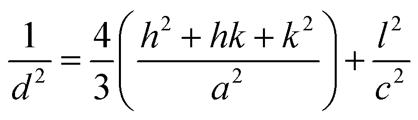
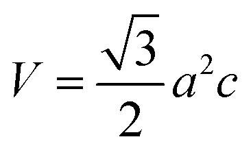
Fig. 6a shows X-ray diffractograms of the ZnO particles before and after heat treatment at 600 °C in air. None of the samples showed any sign of a zinc hydroxy salt structure, indicating that the thickness of the ZHS layer was below the X-ray detection limit e.g. 3 nm.6 This is in accordance with the predicted layer thickness of 1 nm revealed by TG (Section 3.2). All the ZnO samples were highly crystalline with diffraction peaks corresponding to the expected lattice planes with a Miller index of (hkl) in the Wurtzite crystal structure. The Wurtzite lattice parameters, e.g. the crystal interplanar distances (d), were calculated from the Bragg equation (λ = 2d![[thin space (1/6-em)]](https://www.rsc.org/images/entities/char_2009.gif) sinθ); the lattice constants a and c and the crystal unit-cell volume (V) were obtained from the lattice geometry equations:59
sinθ); the lattice constants a and c and the crystal unit-cell volume (V) were obtained from the lattice geometry equations:59
 | (3) |
 | (4) |
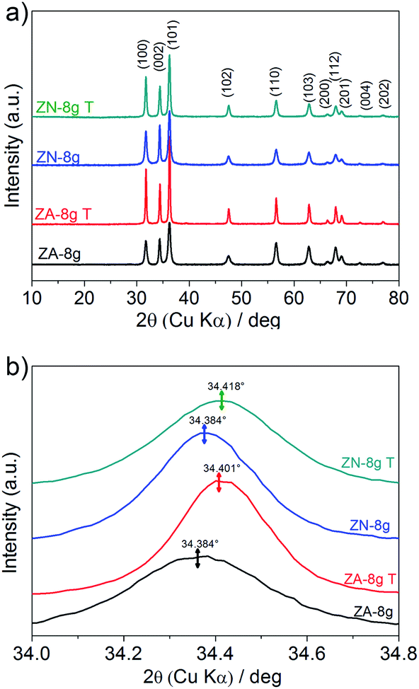 | ||
| Fig. 6 (a) X-ray diffractograms of ZnO particles before (data obtained from ref. 6) and after heat treatment at 600 °C in air (marked T in the figure). (b) Close-up of the (002) diffraction peaks for the different samples. | ||
Fig. 6b shows a slight peak shift to higher diffraction angles, i.e. a shorter interplanar distance and a smaller unit cell volume, as a result of the heat treatment (Table 1). The shrinkage of the unit cell is in accordance with earlier published data, which was attributed to the relaxation of defects inside the crystal unit cells, e.g. zinc and oxygen vacancies.60,61 In order to gain more information about the crystal defects, photoluminescence measurements were conducted on ZnO samples before and after heat treatment (Fig. 7). All the samples showed a strong and broad emission band in the ultraviolet, violet and blue regions (370–500 nm) together with a weak emission band in the green region (520–540 nm). These emissions have been attributed to a variety of vacancy and interstitial defects on the surface and grain boundaries of the ZnO particles.62,63 The onset of the spectra was observed at longer wavelengths for the oriented nanoparticles after heat treatment. In order to clarify this shift, the spectra of oriented nanoparticles before and after heat treatment were deconvoluted into a series of relatively sharp Gaussian peaks centred at 386, 405, 417, 459, 484 and 530 nm. It was observed that the peak at 386 nm (3.21 eV) disappeared and the intensity of the peak at 405 nm (3.06 eV) clearly decreased. The former peak was assigned to near-band-edge emission, and the latter was responsible for electron transition from the conduction band to the zinc vacancy as an acceptor level, 0.3 eV above the valance band.62 These high energy transitions were attributed to poor crystal quality and the presence of band-edge defects64 in ZnO nanoparticles before heat treatment. However, the heat treatment of oriented ZnO nanoparticles removed the high-energy barrier of crystal lattice defects with reference to that of the non-oriented ZnO nanoparticles.
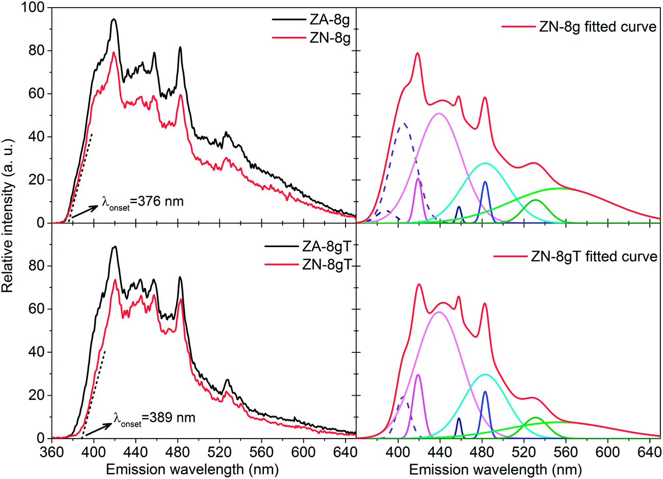 | ||
| Fig. 7 Photoluminescence spectra of ZnO particles before (top) (data obtained from ref. 6) and (bottom) after heat treatment at 600 °C in air together with deconvoluted peaks. The excitation wavelength was 290 nm. | ||
The crystal size increased by 55% and 14%, respectively, for ZA-8g and ZN-8g, indicating that there were significant crystal lattice diffusion and grain growth of the non-oriented nanoparticles compared to the oriented nanoparticles inside the flower-shaped particles (Table 1). Yang et al.65 found repulsive dipole–dipole interactions between nanoparticle surfaces inside oriented nanoparticle aggregates, which inhibited the fusion of ZnO crystals during synthesis. It is suggested here that this repulsive energy between oriented nanoparticles inside submicron flower-shaped particles inhibited the crystal growth during the heat treatment. The crystal aspect ratio (Dc-axis/Da-axis) showing the crystal habit66 decreased by 6% and 32% for the non-oriented and oriented nanoparticle systems, respectively, during heat treatment. The aspect ratio of the ZnO crystals in all the systems was close to 1 after heat treatment, which means that the heat treatment changed the crystallographic direction growth and made the crystals equiaxial. This process occurred due to the surface and volume diffusion on solitary particles or Ostwald ripening by the contribution of the adjacent particles during heat treatment (see Fig. 2b inset). Suvaci and Özer29 showed that the ZnO templates aligned on the c-axis grew anisotropically during sintering. The ZnO nanoparticles with a pyramidal morphology exhibit a basal polar zinc plane of (001) and nonpolar prismatic planes of (110) and (100) with both zinc and oxygen termination.67 The grain growth of the ZnO nanoparticles during post heat treatment was greater for nonpolar prismatic planes than for polar planes.33 Therefore, the nanoparticles aligned along the c-axis; the prismatic crystal planes grew faster due to the more favourable zinc and oxygen atom arrangements,29,68 resulting in lower grain growth along the c direction for oriented particles. This shows that particle orientation can be used as a method to obtain dense ceramics with minimal grain growth during heat treatment. The previous sintering methods (for example in ref. 19, 36 and 42) to obtain fully-dense ZnO ceramics are not able to retain the grain size less than 100 nm under low temperature heat treatment (i.e. below 600 °C). In contrast, we show that the orientation of ZnO nanoparticles could pave the way to achieve a new generation of ultra-dense ZnO ceramics for varistor applications with grain sizes less than 25 nm and a large number of grain boundaries per unit volume.
3.4. Grain growth of coated ZnO nanoparticles
Fig. 8 shows scanning electron micrographs of ZnO nanoparticles with and without OTMS coating on the nanoparticle surfaces, which were heat-treated for 1 h in nitrogen at different temperatures. The heat treatment was carried out in nitrogen in order to avoid the effect of oxygen from the surrounding air on the ZnO sintering process. The average size of the ZnO nanoparticles without coating was essentially unaffected by heat treatment at 600 °C. More subtle changes in the particles occurred, such as rounding of the sharp edges of the nanoparticles. The grain size increased sharply with increasing heat treatment temperature above 800 °C. The OTMS coating on ZnO nanoparticle surfaces inhibited the grain growth, and the sintering occurred at temperatures above 1000 °C. The grain growth of ZnO particles has been extensively investigated for more than 50 years.39,40,69–73 The kinetics of the grain growth is conveniently described by:73 | (5) |
| G = 1.56L | (6) |
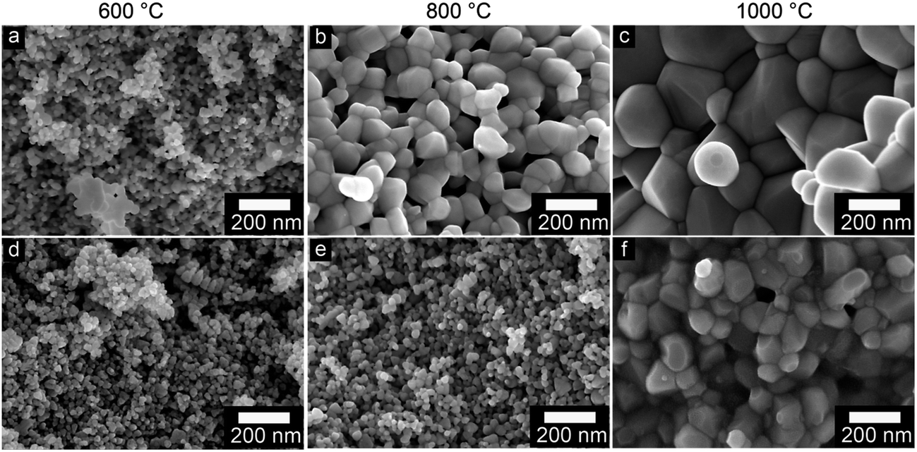 | ||
| Fig. 8 Scanning electron micrographs of (a–c) pristine and (d–f) OTMS-coated ZnO nanoparticles after heat treatment in nitrogen for 1 h at different temperatures. | ||
Fig. 9a shows the isothermal grain growth of the ZnO nanoparticles with and without coating as a function of heat treatment time. The kinetic grain growth exponent was obtained from the slope of the fitted line of logG vs. logt, which is 1/n. The slope of the fitted line of lnG vs. T−1 gives the activation energy (Fig. 9b, Table 2). The high activation energies of pristine ZnO nanoparticles suggested that the volume diffusion was the rate-controlling mechanism. However, the low activation energy obtained with the OTMS surface coating on the ZnO particles indicated that surface diffusion was the dominating sintering mechanism at temperatures below 800 °C. At 1000 °C, the surface diffusion changed to volume diffusion, resulting in larger grains at higher temperatures. It was concluded that silane coating is an effective way for impeding the grain growth during heat treatment and the removal of surface defects.
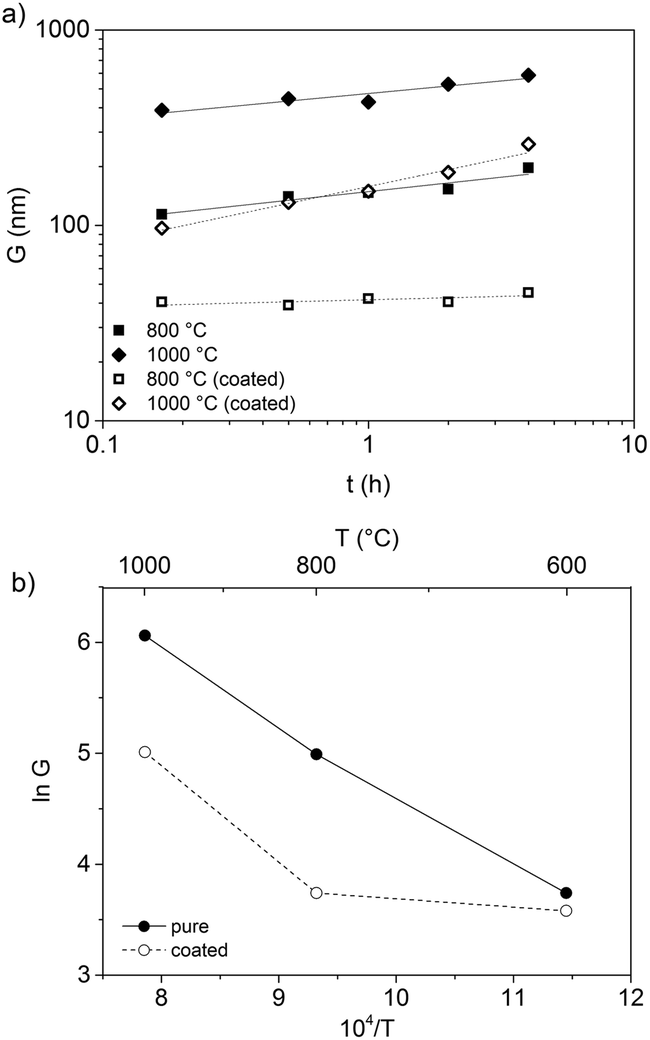 | ||
| Fig. 9 (a) Isothermal grain growth rate (log scale) plotted as a function of time (log scale) for ZA-8g nanoparticles with and without coating. Ambient medium: nitrogen. (b) Arrhenius plot of the grain growth rate for coated and uncoated ZA-8g nanoparticles. | ||
| Sample | n LT | n HT | Q LT (kJ mol−1) | Q HT (kJ mol−1) |
|---|---|---|---|---|
| a LT and HT were used for temperatures below and above 800 °C, respectively. | ||||
| ZA-8g (pristine) | 7.8 | 6.8 | 332 | 253 |
| ZA-8g (coated) | 28.9 | 3.5 | 180 | 475 |
Heat treatment transformed the silane coating to silica while the zinc hydroxy salt defects decomposed, yielding pure ZnO. It was necessary to remove the silica layer in order to produce nano-sized ZnO with an active hydroxylated surface. The presence of the hydroxyl groups on ZnO surfaces is of paramount importance due to their pronounced effect on the chemical activity of the nanoparticles in nanocomposites.52 XPS was used to characterize the surface composition. Fig. 10a–c show the high resolution spectra of the C 1s, Si 2p and O 1s photoelectrons for the synthesized nanoparticles (ZA-8g), the silica-coated nanoparticles after heat treatment at 600 °C (TS) and the sample etched with NaOH solution (TS-E). The C 1s region shows two peaks for the ZA-8g sample at 285.0 and 288.9 eV due to C–C and CO bonds75 in acetate groups on the ZnO nanoparticle surfaces in the ZHS phase.76 These peaks were absent after coating/heat treatment of the TS sample, indicating that ZHS defects had been removed by the heat treatment. The Si 2p region shows that the silica peak at 102.4 eV was absent after the etching of ZnO nanoparticle surfaces with NaOH solution. The O 1s region shows one peak at 530.0 eV with a large shoulder at 531.4 eV for the ZA-8g sample, assigned to O2− ions in the Wurtzite structure and OH groups on the synthesized ZnO nanoparticle surfaces, respectively. The peak assigned to hydroxyl groups disappeared after coating/heat treatment of the TS sample. This peak reappeared after etching the silica shell in the TS-E sample, indicating the hydroxylated surface of the final ZnO nanoparticles. The coating/heat treatment/etching process thus provided the nano-sized ZnO particles with activated hydroxyl surfaces without the presence of associated ionic species. These ultra-pure ZnO nanoparticles with the capability of up-scaling have not been reported to the best of our knowledge. These nanoparticles show their high potential in ultra-low electrically conductive nanocomposites where the absence of the ionic/polar species is of paramount importance.
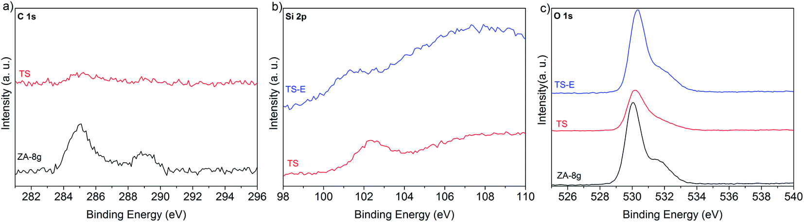 | ||
| Fig. 10 High resolution XPS spectra of synthesized nanoparticles (ZA-8g), silica-coated nanoparticles after the heat treatment at 600 °C (TS) and the sample etched with NaOH solution (TS-E). | ||
4. Conclusions
This study presents two methods using a suitable particle orientation and coating of ZnO nanoparticles to obtain nano-sized and ultra-pure ZnO grains/particles in a single-step heat treatment at low temperatures. The oriented nanoparticle systems obtained by the initial synthesis were more densely packed than the systems consisting of non-oriented nanoparticles and this led to a reduction in the grain growth during heat treatment. The nano-sized and dense ZnO ceramics with a high concentration of grain boundaries have a potential use in varistor applications. Another method was based on silane coating of ZnO nanoparticles which inhibited the sintering during heat treatment. The hydroxylated surface of the ZnO nanoparticles was recovered by alkaline etching of the silica shell. This process makes possible the synthesis of ultra-pure nanoparticles with a hydroxide functional surface and, most importantly, without the presence of counter-ions. These nanoparticles have potential for use in polyethylene nanocomposites within the insulating layer of extruded HVDC cables.Acknowledgements
The Swedish Foundation for Strategic Research (EM11-0022) is acknowledged for providing the financial support for this study.References
- H. Sellerholm, Report 14:21, Elforsk AB, Stockholm, 2014.
- A. Gustafsson, M. Saltzer, A. Farkas, H. Ghorbani, T. Quist and M. Jeroense, The new 525 kV extruded HVDC cable system, ABB Grid Systems, 2014 Search PubMed.
- F. Tian, Q. Lei, X. Wang and Y. Wang, Appl. Phys. Lett., 2011, 99, 142903 CrossRef PubMed.
- D. Liu, A. M. Pourrahimi, R. T. Olsson, M. S. Hedenqvist and U. W. Gedde, Eur. Polym. J., 2015, 66, 67–77 CrossRef CAS PubMed.
- L. K. H. Pallon, R. T. Olsson, D. Liu, A. M. Pourrahimi, M. S. Hedenqvist, A. T. Hoang, S. Gubanski and U. W. Gedde, J. Mater. Chem. A, 2015, 3, 7523–7534 CAS.
- A. M. Pourrahimi, D. Liu, L. K. H. Pallon, R. L. Andersson, A. Martinez Abad, J. M. Lagaron, M. S. Hedenqvist, V. Strom, U. W. Gedde and R. T. Olsson, RSC Adv., 2014, 4, 35568–35577 RSC.
- A. Degen and M. Kosec, J. Eur. Ceram. Soc., 2000, 20, 667–673 CrossRef CAS.
- S. Musić, Đ. Dragčević and S. Popović, J. Alloys Compd., 2007, 429, 242–249 CrossRef PubMed.
- S. Liu, E. Killen, M. Lim, C. Gunawan and R. Amal, RSC Adv., 2014, 4, 4363–4370 RSC.
- F. Demoisson, R. Piolet and F. Bernard, Cryst. Growth Des., 2014, 14, 5388–5396 CAS.
- A. Moezzi, A. McDonagh, A. Dowd and M. Cortie, Inorg. Chem., 2012, 52, 95–102 CrossRef PubMed.
- H. Morioka, H. Tagaya, J. I. Kadokawa and K. Chiba, J. Mater. Sci. Lett., 1999, 18, 995–998 CrossRef CAS.
- A. Moezzi, M. B. Cortie and A. M. McDonagh, Dalton Trans., 2013, 14432–14437 RSC.
- X. Zhao, F. Zhang, S. Xu, D. G. Evans and X. Duan, Chem. Mater., 2010, 22, 3933–3942 CrossRef CAS.
- D. Segets, R. Marczak, S. Schäfer, C. Paula, J.-F. Gnichwitz, A. Hirsch and W. Peukert, ACS Nano, 2011, 5, 4658–4669 CrossRef CAS PubMed.
- D. Sun, M. Wong, L. Sun, Y. Li, N. Miyatake and H.-J. Sue, J. Sol-Gel Sci. Technol., 2007, 43, 237–243 CrossRef CAS.
- Y. Piao, J. Kim, H. B. Na, D. Kim, J. S. Baek, M. K. Ko, J. H. Lee, M. Shokouhimehr and T. Hyeon, Nat. Mater., 2008, 7, 242–247 CrossRef CAS PubMed.
- J. I. Hong, L. S. Schadler, R. W. Siegel and E. Mårtensson, Appl. Phys. Lett., 2003, 82, 1956–1958 CrossRef CAS PubMed.
- N. Neves, R. Barros, E. Antunes, I. Ferreira, J. Calado, E. Fortunato and R. Martins, J. Am. Ceram. Soc., 2012, 95, 204–210 CrossRef CAS PubMed.
- T. K. Gupta, J. Am. Ceram. Soc., 1990, 73, 1817–1840 CrossRef CAS PubMed.
- M. Maleki Shahraki, S. Ali Shojaee, M. A. Faghihi Sani, A. Nemati and I. Safaee, Solid State Ionics, 2011, 190, 99–105 CrossRef PubMed.
- M. Michio, Jpn. J. Appl. Phys., 1971, 10, 736 CrossRef.
- M. Takata, D. Tsubone and H. Yanagida, J. Am. Ceram. Soc., 1976, 59, 4–8 CrossRef CAS PubMed.
- M. Chaari, Mater. Sci. Appl., 2011, 765–770 CAS.
- X. Li, L. Xu, L. Liu, Y. Wang, X. Cao, Y. Huang, C. Meng and Z. Wang, J. Mater. Chem. A, 2014, 2, 16740–16745 CAS.
- S. C. Pillai, J. M. Kelly, R. Ramesh and D. E. McCormack, J. Mater. Chem. C, 2013, 1, 3268–3281 RSC.
- L. Meng, L. Zheng, L. Cheng, G. Li, L. Huang, Y. Gu and F. Zhang, J. Mater. Chem., 2011, 21, 11418–11423 RSC.
- D. Nina, B. Slavko and R. Aleksander, J. Phys.: Conf. Ser., 2011, 326, 012003 CrossRef.
- E. Suvaci and İ. Ö. Özer, J. Eur. Ceram. Soc., 2005, 25, 1663–1673 CrossRef CAS PubMed.
- P. Durán, F. Capel, J. Tartaj and C. Moure, Adv. Mater., 2002, 14, 137–141 CrossRef.
- D. Dollimore and P. Spooner, Trans. Faraday Soc., 1971, 67, 2750–2759 RSC.
- S.-D. Shin, C.-S. Sone, J.-H. Han and D.-Y. Kim, J. Am. Ceram. Soc., 1996, 79, 565–567 CrossRef CAS PubMed.
- D. E. Wurster, E. Oh and J. C. T. Wang, J. Pharm. Sci., 1995, 84, 1301–1307 CrossRef CAS PubMed.
- I. W. Chen and X. H. Wang, Nature, 2000, 404, 168–171 CrossRef CAS PubMed.
- B. Chen, Z. Xia and K. Lu, J. Eur. Ceram. Soc., 2013, 33, 2499–2507 CrossRef CAS PubMed.
- M. Mazaheri, A. M. Zahedi and S. K. Sadrnezhaad, J. Am. Ceram. Soc., 2008, 91, 56–63 CrossRef CAS PubMed.
- R. Roy, D. Agrawal, J. Cheng and S. Gedevanishvili, Nature, 1999, 399, 668–670 CrossRef CAS.
- T. Hungría, J. Galy and A. Castro, Adv. Eng. Mater., 2009, 11, 615–631 CrossRef PubMed.
- T. Senda and R. C. Bradt, J. Am. Ceram. Soc., 1990, 73, 106–114 CrossRef CAS PubMed.
- J. Han, P. Q. Mantas and A. M. R. Senos, J. Eur. Ceram. Soc., 2000, 20, 2753–2758 CrossRef CAS.
- M. Mazaheri, S. A. Hassanzadeh-Tabrizi and S. K. Sadrnezhaad, Ceram. Int., 2009, 35, 991–995 CrossRef CAS PubMed.
- A. P. Hynes, R. H. Doremus and R. W. Siegel, J. Am. Ceram. Soc., 2002, 85, 1979–1987 CrossRef CAS PubMed.
- A. P. A. Oliveira, J.-F. Hochepied, F. Grillon and M.-H. Berger, Chem. Mater., 2003, 15, 3202–3207 CrossRef CAS.
- Z. Zhang, H. Sun, X. Shao, D. Li, H. Yu and M. Han, Adv. Mater., 2005, 17, 42–47 CrossRef CAS PubMed.
- J. Mouzon, M. Odén, O. Tillement and Y. Jorand, J. Am. Ceram. Soc., 2006, 89, 3094–3100 CrossRef CAS PubMed.
- X. Gu, S. Sabuktagin, A. Teke, D. Johnstone, H. Morkoç, B. Nemeth and J. Nause, J. Mater. Sci.: Mater. Electron., 2004, 15, 373–378 CrossRef CAS.
- D. V. Wagle and G. A. Baker, Mater. Horiz., 2015, 2, 157–167 RSC.
- P. Uthirakumar, B. Karunagaran, S. Nagarajan, E.-K. Suh and C.-H. Hong, J. Cryst. Growth, 2007, 304, 150–157 CrossRef CAS PubMed.
- Y. Wang, Y. Li, Z. Zhou, X. Zu and Y. Deng, J. Nanopart. Res., 2011, 13, 5193–5202 CrossRef CAS.
- G. R. Williams, J. Crowder, J. C. Burley and A. M. Fogg, J. Mater. Chem., 2012, 22, 13600–13611 RSC.
- H. Staroszczyk and P. Janas, Carbohydr. Polym., 2010, 80, 962–969 CrossRef CAS PubMed.
- H. Noei, H. Qiu, Y. Wang, E. Loffler, C. Woll and M. Muhler, Phys. Chem. Chem. Phys., 2008, 10, 7092–7097 RSC.
- H. Wang and C. Xie, J. Phys. Chem. Solids, 2008, 69, 2440–2444 CrossRef CAS PubMed.
- S. J. Gregg and K. S. W. Sing, Adsorption, surface area, and porosity, Academic Press, 1991 Search PubMed.
- K. Kaneko, J. Membr. Sci., 1994, 96, 59–89 CrossRef CAS.
- M.-Y. Chu, M. N. Rahaman, L. C. de Jonghe and R. J. Brook, J. Am. Ceram. Soc., 1991, 74, 1217–1225 CrossRef CAS PubMed.
- L. C. De Jonghe, M.-Y. Chu and M. F. Lin, J. Mater. Sci., 1989, 24, 4403–4408 CrossRef CAS.
- F. Wakai, Y. Shinoda and T. Akatsu, Acta Mater., 2004, 52, 5621–5631 CrossRef CAS PubMed.
- C. Suryanarayana and M. G. Norton, X-ray diffraction: a practical approach, Springer, 1998 Search PubMed.
- H. Zeng, G. Duan, Y. Li, S. Yang, X. Xu and W. Cai, Adv. Funct. Mater., 2010, 20, 561–572 CrossRef CAS PubMed.
- A. K. Zak, M. E. Abrishami, W. Majid, R. Yousefi and S. Hosseini, Ceram. Int., 2011, 37, 393–398 CrossRef CAS PubMed.
- S. Vempati, J. Mitra and P. Dawson, Nanoscale Res. Lett., 2012, 7, 1–10 CrossRef PubMed.
- Z. Chen, N. Zhang and Y.-J. Xu, CrystEngComm, 2013, 15, 3022–3030 RSC.
- Y. H. Leung, Z. B. He, L. B. Luo, C. H. A. Tsang, N. B. Wong, W. J. Zhang and S. T. Lee, Appl. Phys. Lett., 2010, 96, 053102 CrossRef PubMed.
- M. Yang, K. Sun and N. A. Kotov, J. Am. Chem. Soc., 2010, 132, 1860–1872 CrossRef CAS PubMed.
- X. Pan, M.-Q. Yang and Y.-J. Xu, Phys. Chem. Chem. Phys., 2014, 16, 5589–5599 RSC.
- X. Liu and M. T. Swihart, Nanoscale, 2013, 5, 8029–8036 RSC.
- L. Vayssieres, K. Keis, A. Hagfeldt and S.-E. Lindquist, Chem. Mater., 2001, 13, 4395–4398 CrossRef CAS.
- J. Wu, T. Li, C. Wang, B. Zhu, R. Wu and C. Xie, Ceram. Int., 2011, 37, 3469–3476 CrossRef CAS PubMed.
- X. J. Qin, G. J. Shao, R. P. Liu and W. K. Wang, J. Mater. Sci., 2005, 40, 4943–4946 CrossRef CAS.
- J. Wong, J. Appl. Phys., 1980, 51, 4453–4459 CrossRef CAS PubMed.
- T. K. Gupta and R. L. Coble, J. Am. Ceram. Soc., 1968, 51, 521–525 CrossRef CAS PubMed.
- G. C. Nicholson, J. Am. Ceram. Soc., 1965, 48, 214–215 CrossRef CAS PubMed.
- M. I. Mendelson, J. Am. Ceram. Soc., 1969, 52, 443–446 CrossRef CAS PubMed.
- B. Weng, M.-Q. Yang, N. Zhang and Y.-J. Xu, J. Mater. Chem. A, 2014, 2, 9380–9389 CAS.
- S.-W. Bian, I. A. Mudunkotuwa, T. Rupasinghe and V. H. Grassian, Langmuir, 2011, 27, 6059–6068 CrossRef CAS PubMed.
Footnote |
| † Electronic supplementary information (ESI) available. See DOI: 10.1039/c5ta03120f |
| This journal is © The Royal Society of Chemistry 2015 |