 Open Access Article
Creative Commons Attribution 3.0 Unported Licence
Free-standing composite hydrogel films for superior volumetric capacitance†
Mahmoud
Moussa
ab,
Zhiheng
Zhao
a,
Maher F.
El-Kady
cd,
Huakun
Liu
e,
Andrew
Michelmore
a,
Nobuyuki
Kawashima
a,
Peter
Majewski
a and
Jun
Ma
*a
aMawson Institute and School of Engineering, University of South Australia, Mawson Lakes, SA5095, Australia. E-mail: Jun.Ma@unisa.edu.au
bDepartment of Chemistry, Faculty of Science, Beni-Suef University, Beni-Suef 62111, Egypt
cDepartment of Chemistry & Biochemistry California NanoSystems Institute, University of California Los Angeles (UCLA), Los Angeles, CA 90095, USA
dDepartment of Chemistry, Faculty of Science, Cairo University, Giza 12613, Egypt
eInstitute for Superconducting and Electronic Materials (ISEM), University of Wollongong, 2522 NSW, Australia
First published on 19th June 2015
Abstract
High volumetric capacitance is vital for the development of wearable and portable energy storage devices. We herein introduce a novel simple route for the fabrication of a highly porous, binder-free and free-standing polyaniline/reduced graphene oxide composite hydrogel (PANi/graphene hydrogel) as an electrode with a packing density of 1.02 g cm−3. PANi played critical roles in gelation, which include reduction, crosslinking, creation of pseudocapacitance and as a spacer preventing graphene sheets from stacking. The composite hydrogel film delivered a volumetric capacitance of 225.42 F cm−3 with a two-electrode supercapacitor configuration, which was enhanced to 592.96 F cm−3 in a redox-active electrolyte containing hydroquinone. This new strategy will open a new area for using conducting polymer derivatives in the development of flexible graphene electrodes towards many applications such as batteries, sensors and catalysis.
Introduction
Recently, flexible electrodes have received increasingly more attention because of their extensive applications in bendable, wearable and portable electronic devices, especially flexible energy storage devices such as supercapacitors and batteries.1,2 Supercapacitors or ultracapacitors are advantageous over batteries due to their high power density, fast charge–discharge rates, long cycle life, safety, cost-effectiveness and environmental friendliness. Graphene, a flat monolayer of sp2 hybridized carbon atoms, is considered as the most promising candidate for flexible supercapacitor electrodes.3,4 But graphene sheets just stack themselves leading to graphite-like behaviour, and an effective solution to this problem is to use polymers as spacers between the sheets.5–11Mechanically robust graphene hydrogels hold promise for the development of flexible electrodes, because they demonstrate high flexibility, low ion diffusion resistance yet large ion-accessible surface areas. These gels were initially developed by a hydrothermal treatment of graphene oxide (GO) suspension, and they showed a specific capacitance of 175 to 190 F g−1.12,13 To further increase the capacitance, Xu et al. prepared a graphene hydrogel film using a hydrothermal process followed by pressing with a gold-coated polyimide substrate, and the film was then functionalized with hydroquinone; the functionalization improved the specific capacitance from 190 to 441 F g−1.14,15 Recently, the treatment appears to have been replaced by chemical reactions at an elevated temperature with no pressurized containers involved.16 For instance, a graphene hydrogel fabricated by the reduction of GO with L-glutathione showed a specific capacitance of 157.7 F g−1.17 Another hydrogel was fabricated by crosslinking GO with ethylenediamine, subsequently reduced by hydrazine, delivering a specific capacitance of 232 F g−1.18 Synergistic effects on capacitance were observed between conducting polymers, graphene and carbon nanotubes, leading to a high specific capacitance of 498 F g−1.19 However, it is unknown whether conducting polymers can form hydrogels; if so, what will be the capacitance.
Volumetric capacitance – a paramount metric in real industrial applications – is indeed far more important than gravimetric capacitance for portable devices in need of as much energy storage as possible in rather limited space.20 A compressed holey graphene oxide framework, which was hydrothermally prepared in the presence of H2O2, showed a gravimetric capacitance of 298 F g−1 and a volumetric capacitance of 212 F cm−3 in an organic electrolyte.21 Yang et al. prepared a chemically reduced, free-standing graphene oxide hydrogel film by a capillary compression process, which exhibited a volumetric capacitance of 255.5 F cm−3.22 The highest volumetric capacitance of 376 F cm−3 to date was reported by Tao et al. who developed a highly dense graphene by evaporation-induced drying of a graphene hydrogel.23
The current study introduces a new strategy for the development of a free-standing hydrogel composite film consisting of polyaniline (PANi) and reduced graphene oxide sheets, where PANi plays multi-roles including reduction, crosslinking, as a spacer to wedge open stacked graphene sheets, and an additive for pseudocapacitance. As noted before, GO can be partially reduced during the in situ polymerization of aniline24–26 or during its contact with some conjugated polymers such as poly(m-phenylenediamine) to produce a composite through a redox reaction.27 A dopant poly(2-acrylamido-2-methyl-1-propanesulfonic acid (PAMPA)) is selected for PANi because it has extraordinary stability under high oxidizing potentials and also it improves water accessibility to PANi.28 The obtained free-standing hydrogel film electrodes have high flexibility and an interconnected porous structure, and they deliver the highest gravimetric (Cwt = 580.52 F g−1) and volumetric (Cvol = 592.96 F cm−3) capacitance values among all the reported porous carbon-based supercapacitors to date.
Experimental
Materials
Graphite powder was provided by Adelaide Moulding & Casting Supplies; Product Code: 325 Mesh (45 micron). Poly(2-acrylamido-2-methyl-1-propanesulfonic acid (PAMPA); Mw = 800 kg mol−1) was delivered from Scientific Polymer Products. Aniline, ammonium persulfate (APS), potassium permanganate (KMnO4), sulphuric acid (H2SO4), phosphoric acid (H3PO4), hydrogen peroxide (H2O2), and hydroquinone (HQ) were purchased from Sigma-Aldrich. All chemicals were used without further purification.Synthesis of polyaniline: poly(2-acrylamido-2-methyl-1-propanesulfonic acid)
The synthesis of a compound containing polyaniline and poly(2-acrylamido-2-methyl-1-propanesulfonic acid) (denoted as PANi-PAMPA) was carried out according to a previous report.28 In brief, 1.65 g of PAMPA was dissolved in 107.14 ml of deionized water, into which 0.74 g of aniline monomers was added, followed by stirring for 1 h at room temperature. APS (4.6 g) was dissolved in 7.14 ml of deionized water. Afterwards, these two batches of solutions were purged with nitrogen gas for 1 h. Then the APS solution was added dropwise at 1.25 ml min−1 to the aniline-PAMPA solution to start the polymerization lasting 24 h. Finally, 200 ml of acetone was used to precipitate the PANi-PAMPA composite. The resulting polymer was washed several times with acetone and dried under vacuum at room temperature giving 93% yield.Synthesis of graphene oxide
Graphene oxide (GO) was prepared as per a previous study.29 In brief, graphite powder (0.5 g) was mixed under stirring with a mixture of 60 ml H2SO4 and 6.6 ml H3PO4, and then 3 g of KMnO4 was slowly blended with the mixture within 1 h in an ice bath. Subsequently the reaction system was transferred to an oil bath, with the temperature raised to 50 °C and stirring for 24 h. After that, the reaction was lifted for cooling down to room temperature and poured into a mixture of 200 ml ice and 1 ml H2O2 (30%). The produced GO was centrifuged and washed with 1 M HCl solution and deionized water, respectively, to remove the residual metal ions and acids. The final GO paste was dried at 60 °C for 48 h for the following synthesis.Synthesis of a polyaniline/graphene hydrogel film
A polyaniline (PANi)/graphene hydrogel was prepared according to the following steps. 60 mg GO (90 wt%) and 7 mg PANi-PAMPA (10 wt%) were dispersed, respectively, in 10 ml and 5 ml of deionized water, both with ultrasonication for 1 h. The two batches of solutions were stir-mixed, followed by sonication for another 1 h. Subsequently the mixture was heated at 95 °C for 30 h with no stirring to form a PANi/graphene hydrogel. The hydrogel was added into 60 ml deionized water with vigorous stirring, turning the hydrogel monolith into many tiny pieces. Next, the resulting suspension was filtered through a PTFE membrane to form a hydrogel film. The film was easily peeled off from the filter paper after drying under vacuum at room temperature for 4 h. The composites with over 10 wt% of PANi obviously showed lower mechanical strength, and thus the 10 wt% composite hydrogel was used throughout this study. The hydrogel film of ∼7 μm in thickness was then washed several times with deionized water, and was immersed again in water for 24 h to remove unreacted materials, producing the end product – a PANi/graphene hydrogel composite film – for the following application.Supercapacitor fabrication and electrochemical characterization
The composite film was cut into small pieces, each of which has a surface area of 1 cm2; these pieces were dipped into electrolytes overnight which can be either 1 M H2SO4 or a mixture of 1 M H2SO4 and 0.4 M hydroquinone (HQ) (H2SO4/HQ). Two identical films were attached to Pt foil as current collectors, and then the electrodes were sandwiched by a piece of filter paper as the separator. All electrochemical measurements, such as cyclic voltammetry (CV), galvanostatic charge/discharge (CD) and electrochemical impedance spectroscopy (EIS), were performed by a two-electrode configuration using a CHI 660E electrochemical workstation. The CV testings were done between −0.2 and 0.8 V at different scan rates from 5 to 100 mV s−1. The CD measurements were carried out in a voltage window between 0 and 0.8 V at 0.4–10 A g−1. The EIS spectra were recorded from 100 kHz to 10 mHz at an open circuit potential with an AC voltage amplitude of 5 mV. All measurements were performed at room temperature.Results and discussion
PANi/graphene composites
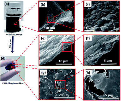
Fig. 1 illustrates our simple method for the preparation of a polyaniline (PANi)/graphene hydrogel film. We adopted graphene oxide (GO) in this study because it has shown great potential in the development of energy storage devices8,10,11,30–34 and other applications.7,9,35 When the GO suspension was mixed with the solution of PANi and poly(2-acrylamido-2-methyl-1-propanesulfonic acid) (denoted PAMPA), an electrostatic interaction was immediately created between the negatively charged carboxylic groups of GO and the positively charged nitrogen atoms of both PANi and PAMPA (Fig. S1a† contains the polymers' morphology); leaving the mixture at 95 °C for 12 h changed the colour from brown to black. While PAMPA may crosslink PANI, the PANi-PAMPA solution has the following roles: (i) reducing GO and (ii) interleaving graphene sheets as a spacer; this would produce an impressive pseudocapacitance that is to be discussed later. Heating the mixture at 95 °C for 30 h created a cylindrical shape of the PANi/graphene hydrogel (Fig. 2a). The hydrogel morphology may consist of particulates, nanotubes and nanofibers, as shown in the ESI Fig. S1;† Fig. S2† contains images of the hydrogels. The hydrogel used in the following measurement contains 99.33 wt% H2O, 0.07 wt% PANi and 0.60 wt% graphene. The internal micro-porous network of the freeze-dried hydrogel is clearly seen in Fig. 2b and c.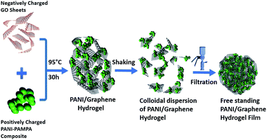 | ||
| Fig. 1 A schematic diagram of the formation of a polyaniline (PANI)/graphene hydrogel (graphene refers to reduced graphene oxide). | ||
We report below a new method for the fabrication of a hydrogel composite film. The cylindrical PANi/graphene hydrogel obtained from the last step was sheared into many tiny pieces in deionized water by vigorous stirring, producing a colloidal suspension; by filtration and drying, we created a flexible and free-standing PANi/graphene hydrogel film (Fig. 2d). This filtration process contributes to a higher volumetric capacitance because it created a film of controllable lower thickness (∼7 μm) for supercapacitor electrodes than the original composite hydrogel. The cross section and surface of the film are shown in Fig. 2f, h and S3,† all of which reveal orderly layered graphene sheets with a porous structure. Fig. 2f shows polymeric particles embedded between the graphene layers providing exactly more interspace and high accessibility to the electrolyte ions.
Raman scattering was used to elucidate the structural integrity of GO and its composite hydrogel (Fig. 3a). The Raman spectra displayed two peaks, a D band at 1348 cm−1 relating to the conversion of sp2 to sp3-hybridized carbon and a G band at 1590 cm−1 corresponding to the vibration of a sp2-hybridized carbon. The ID/IG intensity ratio provides a major tool to determine the degree of disorder and the information of sp2 domains. After the PANi-PAMPA treatment, the ID/IG intensity ratio increases from 1.03 for GO to 1.11 for a PANi/graphene hydrogel, indicating the role of PANi in reducing GO.
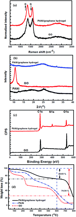 | ||
| Fig. 3 Characterization of the graphene oxide and PANi/graphene hydrogel: (a) Raman spectra, (b) XRD, (c) XPS and (d) TGA. | ||
Fig. 3b describes the XRD patterns of PANi, GO sheets and their hydrogel films. The characteristic diffractions of PANi-PAMPA are centred at 2θ values of 20.1° and 25.3°, which attribute to the crystallinity and the coherence length of aligned polymer chains;36 a sharp and intense diffraction at 10.6° corresponds to an interplanar spacing of 0.83 nm of GO sheets.37 The reduction of GO by PANi was clearly proved by the disappearance of the diffraction at 10.6° in the hydrogel XRD pattern, in agreement with the Raman analysis. However, a broad diffraction is found at 24.7° for the hydrogel in Fig. 3b corresponding to an interlayer spacing of 0.36 nm which relates to a graphite-like structure (0.33 nm); the broadness implies a wide variety of interlayer spacing which may be caused by inserted polymer particles (Fig. 2f).
High-resolution XPS was used to investigate the compositions of GO and its composite hydrogel (Fig. 3c). The hydrogel survey spectrum shows an N1s peak centred at 399 eV corresponding to the secondary amine groups of PANi indicating its presence. The GO reduction by PANi increased the C/O ratio from 2.52 for GO to 5.27 for the gel (after deducting the contribution from PANi, the C/O ratio is 4.74 for the reduced GO). The reduction led to an increase in sp2 hybridized carbon atoms on the graphene sheets, which enhanced the π–π interaction between graphene and PANi facilitating the electron transfer between graphene and PANi.
Fig. 3d contains the graphs of thermogravimetric analysis (TGA) of PANi, GO and the dried PANi/graphene hydrogel which is an aerogel. For PANi, the weight loss up to 100 °C is due to the elimination of adsorbed water molecules, and the largest weight loss at 200–500 °C should be attributed to the decomposition of low molecular weight PANi. GO displays low thermal stability with three stages of thermal degradation. The weight loss at ∼100 °C is likely due to the removal of physically adsorbed water molecules (stage 1), and the rapid degradation at ∼200 °C is attributed to the removal of oxygen-containing functional groups (stage 2), and the carbon skeleton of the GO decomposed at elevated temperatures between 550 and 650 °C leading to a total weight loss of 74.54% (stage 3). The dried hydrogel film has far better thermal stability than both PANi and GO, as shown by the film weight loss of 28.63% at 600 °C.
It is worth noting that the design of our hydrogel composite film electrodes provides an effective solution to the problem of graphene stacking, where PANi nano-entities, by π–π interaction with graphene sheets, work as a spacer inserted between the graphene sheets; this leads to a high interfacial area and excellent electrolyte diffusion rate throughout the network. Moreover, the produced hydrogel film has high flexibility (Fig. 2d) and high electrical conductivity (5600 S m−1), eliminating the need for polymer binders or conductive additives that are electrochemically inert with low capacity.
Electrochemical performance of PANi/graphene composite hydrogels in 1 M H2SO4
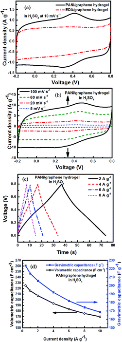
The electrochemical performance of the as-prepared PANi/graphene hydrogel film electrodes was first investigated in 1 M H2SO4. The cyclic voltammetry (CV) curve of PANi/graphene hydrogel films is shown in Fig. 4a, where quasi-rectangles are seen with very weak reversible anodic and cathodic peaks, indicating pseudocapacitance mainly contributed by PANi or residual oxygen-containing functional groups on graphene sheets.To gauge the effect of PANi, we replaced PANi with 40 μl of ethylenediamine (EDA) as the reducing agent to produce a control sample – an EDA/graphene hydrogel film. In Fig. 4a, the characteristic peaks for pseudocapacitance disappear in the EDA/graphene hydrogel with a lower integrated area; and this demonstrates the role of PANi to enhance the electrode capacitance.
The CV curves of PANi/graphene hydrogel electrodes at different scan rates are displayed in Fig. 4b, showing the capacity of the composite hydrogel film to present competitive electrochemical behaviour in a wide range of scan rates. A linear relationship is observed between the capacitive current peaks and the scan rates, confirming that the electrochemical behaviour was mainly determined by the diffusion of H+ into the porous structure of the hydrogel electrodes (Fig. S4a†).
Fig. 4c contains the galvanostatic charge/discharge (CD) curves of the hydrogel film at different scan rates; the deviation from linearity is due to the pseudocapacitance from PANi. The long charge and discharge time is attributed by the incorporation of EDLC and Faradic capacitance, respectively, from graphene sheets and PANi.
Fig. 4d shows the gravimetric (Cwt) and volumetric (Cvol) capacitances of the supercapacitor (density = 1.02 g cm−3) at different current densities, calculated from charge/discharge curves by the following equations:
 | (1) |
 | (2) |
 is the slope of the discharge curve, m is the total mass of the two electrodes (g), and V is the total volume of the two electrodes.
The hydrogel film electrodes display a gravimetric (Cwt) capacitance of 223.82 F g−1 at 0.4 A g−1, which is higher than the chemically reduced graphene gel film (170.60 F g−1) but lower than the holey graphene framework (310.00 F g−1).21,22 On the other hand, the calculated volumetric capacitance based on the packing film density (1.02 g cm−3) was 225.42 F cm−3. As the value is lower than the reported capacitance values such as 255.5 F cm−3 for the graphene gel film22 and 300 F cm−3 for carbon nanotube-graphene fibres,38 we improved our electrode performance by selecting an electrolyte mixture.
Superior performance of the hydrogel composite film
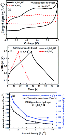
Since hydroquinone (HQ) was reported as an effective redox-active electrolyte providing additional redox reactions,39 we added 0.4 M HQ into 1 M H2SO4 to produce a mixed electrolyte. Using the mixed electrolyte obviously increased the integrated area of cyclic voltammetry (Fig. 5a). In Fig. 5b, the electrolyte shows the longest CD time, where the deviation from the nearly symmetric triangular shape confirms the contribution from HQ.Fig. 5c contains the gravimetric and volumetric capacitances (Cwt and Cvol) of the hydrogel film electrodes in the mixed electrolyte (H2SO4/HQ) at different current densities, which demonstrate remarkably far higher performance (Cwt = 580.52 F g−1 and Cvol = 592.96 F cm−3). As shown in Table S1,† our Cvol is 197% higher than the highest 300 F cm−3 reported to date for flexible supercapacitors.38 Similarly, the areal capacitance per footprint of the device increases from 78.89 mF cm−2 (in H2SO4) to 207.53 mF cm−2 (in H2SO4/HQ) (Fig. S4e†). Thus, our composite hydrogel films are promising for the development of flexible supercapacitors.
Electrochemical impedance spectroscopy (EIS) is essential to understand the electrochemical response of our composite film electrodes. Fig. 6a shows Nyquist plots of the hydrogel electrodes tested, respectively, in H2SO4 and in the mixed electrolyte (H2SO4/HQ). It is apparent that the sample in H2SO4/HQ shows a more obvious semicircle in the high-frequency region (inset in Fig. 6a). By extrapolating the straight portion of the graph, we obtained an equivalent series resistance (ESR) of 1 Ω for the electrodes in H2SO4. By contrast, the sample in H2SO4/HQ presents a much lower ESR at 0.78 Ω due to the high electrical conductivity of the electrolyte.40,41 At low frequency, the hydrogel in H2SO4/HQ demonstrates a more vertical line than the hydrogel in H2SO4, corresponding to the lower diffusion resistance of ions and more capacitance from the HQ's redox behaviour.
In Fig. 6b we made the Ragone plot with the average volumetric energy density (Evol) and the average volumetric power density (Pvol) based on the total volume of electroactive materials in the two electrodes by using the following equations;
 | (3) |
 | (4) |
For the hydrogel electrodes in H2SO4, the average volumetric energy and power density values are, respectively, 5.1 Wh L−1 and 2427.4 W L−1. In case of the H2SO4/HQ electrolyte, much higher values are obtained at 13.2 Wh L−1 and 2636.9 W L−1, corresponding to the gravimetric energy and power density at 12.9 Wh L−1 and 2581.6 W kg−1.
The platinum current collector is 100 μm in thickness, which can be readily bent. The composite hydrogel film supercapacitor with H2SO4/HQ as the electrolyte shows excellent flexibility and can be bent to a large angle with no damage to the structural integrity. While all the previous electrochemical measurements were performed on flat electrodes due to the convenience of fabrication and handling, Fig. 6c shows the CVs of the hydrogel electrodes in H2SO4/HQ with different bending conditions at 100 mV s−1. It is seen that bending does not pose any effect on the capacitance, indicating excellent mechanical stability of our hydrogel electrodes, and this implies potential applications for many portable devices.
The long-term cyclic stability of the hydrogel film electrodes was studied by charge/discharge testing at a current density of 10 A g−1 in both H2SO4 and H2SO4/HQ electrolytes for 5000 cycles (Fig. S4d†). The electrodes in H2SO4/HQ reveal lower cyclic stability (70% of cyclic retention) than that in H2SO4 (87.5%), and this may be due to the extensive redox reactions in the redox electrolyte.40,41 In spite of these, the capacitance in the redox electrolyte is 70% higher than that in H2SO4. The first and last five cycles of the hydrogel electrodes in H2SO4/HQ (inset Fig. 4Sc†) are nearly identical, indicating good reversibility.
A number of supercapacitor units are often connected either in series or parallel to make a tandem cell; this is a traditional way to enhance the ability of the supercapacitor to supply a variety of devices in practical applications. In this study, three composite hydrogel film supercapacitors with H2SO4/HQ as the electrolyte were assembled in series to power a red light emitting diode (LED). The operating potential window was thus extended from 0.8 V for a single device to 2.4 V for the assembled cell (Fig. 6d), and there is no change on the discharge time, revealing the high capability of the cell. Charging the cell at 2.4 V for 30 seconds provided sufficient power to light up the LED for over 6 minutes (inset in Fig. 6d).
Conclusions
To summarize, we developed a simple method for the fabrication of a free-standing conducting polymer/graphene composite hydrogel film. The conducting polymer polyaniline (PANi) played a number of key roles in the fabrication. The composite film has a porous and orderly layered structure where polymeric particles were found between the layers; these particles worked as stiff nano-spacers providing plenty of electrochemical interface for electrolyte ion interactions. When the hydrogel film was used as a flexible supercapacitor electrode in a redox active electrolyte, it revealed the highest gravimetric and volumetric capacitances at 580.52 F g−1 and 592.96 F cm−3, respectively, at a current density of 0.4 A g−1. Furthermore, the hydrogel electrodes provided a maximum volumetric energy density of 13.20 Wh L−1 with an average volumetric power density of 124.08 W L−1.Acknowledgements
The authors thank financial support by the Australian Research Council (LP140100605).References
- L. Liu, Z. Niu, L. Zhang, W. Zhou, X. Chen and S. Xie, Adv. Mater., 2014, 26, 4855–4862 CrossRef CAS PubMed.
- G. Zhou, L. Li, D.-W. Wang, X.-Y. Shan, S. Pei, F. Li and H.-M. Cheng, Adv. Mater., 2015, 27, 641–647 CrossRef CAS PubMed.
- M. F. El-Kady, V. Strong, S. Dubin and R. B. Kaner, Science, 2012, 335, 1326–1330 CrossRef CAS PubMed.
- M. F. El-Kady and R. B. Kaner, Nat. Commun., 2013, 4, 1475 CrossRef PubMed.
- S. Zhu, J. Guo, J. Dong, Z. Cui, T. Lu, C. Zhu, D. Zhang and J. Ma, Ultrason. Sonochem., 2013, 20, 872–880 CrossRef CAS PubMed.
- Z. Sun, J. Guo, S. Zhu, L. Mao, J. Ma and D. Zhang, Nanoscale, 2014, 6, 2186–2193 RSC.
- S. Araby, I. Zaman, Q. Meng, N. Kawashima, A. Michelmore, H.-C. Kuan, P. Majewski, J. Ma and L. Zhang, Nanotechnology, 2013, 24, 165601 CrossRef PubMed.
- Y. Li, S. Zhu, Q. Liu, Z. Chen, J. Gu, C. Zhu, T. Lu, D. Zhang and J. Ma, Water Res., 2013, 47, 4188–4197 CrossRef CAS PubMed.
- S. Araby, L. Zhang, H.-C. Kuan, J.-B. Dai, P. Majewski and J. Ma, Polymer, 2013, 54, 3663–3670 CrossRef CAS PubMed.
- Y. Li, C. Zhu, T. Lu, Z. Guo, D. Zhang, J. Ma and S. Zhu, Carbon, 2013, 52, 565–573 CrossRef CAS PubMed.
- S. Zhu, C. Zhu, J. Ma, Q. Meng, Z. Guo, Z. Yu, T. Lu, Y. Li, D. Zhang and W. M. Lau, RSC Adv., 2013, 3, 6141–6146 RSC.
- Y. Xu, K. Sheng, C. Li and G. Shi, ACS Nano, 2010, 4, 4324–4330 CrossRef CAS PubMed.
- P. Chen, J.-J. Yang, S.-S. Li, Z. Wang, T.-Y. Xiao, Y.-H. Qian and S.-H. Yu, Nano Energy, 2013, 2, 249–256 CrossRef CAS PubMed.
- Y. Xu, Z. Lin, X. Huang, Y. Wang, Y. Huang and X. Duan, Adv. Mater., 2013, 25, 5779–5784 CrossRef CAS PubMed.
- Y. Xu, Z. Lin, X. Huang, Y. Liu, Y. Huang and X. Duan, ACS Nano, 2013, 7, 4042–4049 CrossRef CAS PubMed.
- H. Hu, Z. Zhao, W. Wan, Y. Gogotsi and J. Qiu, Adv. Mater., 2013, 25, 2219–2223 CrossRef CAS PubMed.
- H. Gao, F. Xiao, C. B. Ching and H. Duan, ACS Appl. Mater. Interfaces, 2012, 4, 2801–2810 CAS.
- V. H. Luan, H. N. Tien, L. T. Hoa, N. T. M. Hien, E.-S. Oh, J. Chung, E. J. Kim, W. M. Choi, B.-S. Kong and S. H. Hur, J. Mater. Chem. A, 2013, 1, 208–211 CAS.
- H. Fan, N. Zhao, H. Wang, J. Xu and F. Pan, J. Mater. Chem. A, 2014, 2, 12340–12347 CAS.
- M. Moussa, M. F. El-Kady, H. Wang, A. Michimore, Q. Zhou, J. Xu, P. Majeswki and J. Ma, Nanotechnology, 2015, 26, 075702 CrossRef PubMed.
- Y. Xu, Z. Lin, X. Zhong, X. Huang, N. O. Weiss, Y. Huang and X. Duan, Nat. Commun., 2014, 5, 4554 CAS.
- X. Yang, C. Cheng, Y. Wang, L. Qiu and D. Li, Science, 2013, 341, 534–537 CrossRef CAS PubMed.
- Y. Tao, X. Xie, W. Lv, D.-M. Tang, D. Kong, Z. Huang, H. Nishihara, T. Ishii, B. Li, D. Golberg, F. Kang, T. Kyotani and Q.-H. Yang, Sci. Rep., 2013, 3, 2975 Search PubMed.
- U. Rana and S. Malik, Chem. Commun., 2012, 48, 10862–10864 RSC.
- Y. M. Shulga, S. A. Baskakov, V. V. Abalyaeva, O. N. Efimov, N. Y. Shulga, A. Michtchenko, L. Lartundo-Rojas, L. A. Moreno-R, J. G. Cabañas-Moreno and V. N. Vasilets, J. Power Sources, 2013, 224, 195–201 CrossRef CAS PubMed.
- L. Q. Xu, Y. L. Liu, K.-G. Neoh, E.-T. Kang and G. D. Fu, Macromol. Rapid Commun., 2011, 32, 684–688 CrossRef CAS PubMed.
- L. Zhang, T. Wang, H. Wang, Y. Meng, W. Yu and L. Chai, Chem. Commun., 2013, 49, 9974–9976 RSC.
- J.-W. Jeon, Y. Ma, J. F. Mike, L. Shao, P. B. Balbuena and J. L. Lutkenhaus, Phys. Chem. Chem. Phys., 2013, 15, 9654–9662 RSC.
- D. C. Marcano, D. V. Kosynkin, J. M. Berlin, A. Sinitskii, Z. Sun, A. Slesarev, L. B. Alemany, W. Lu and J. M. Tour, ACS Nano, 2010, 4, 4806–4814 CrossRef CAS PubMed.
- D. Li, D. Shi, Z. Liu, H. Liu and Z. Guo, J. Nanopart. Res., 2013, 15, 1–10 Search PubMed.
- L. Li, K. Seng, D. Li, Y. Xia, H. Liu and Z. Guo, Nano Res., 2014, 7, 1466–1476 CrossRef CAS.
- S. Li, K. Shu, C. Zhao, C. Wang, Z. Guo, G. Wallace and H. K. Liu, ACS Appl. Mater. Interfaces, 2014, 6, 16679–16686 CAS.
- S. Li, C. Zhao, K. Shu, C. Wang, Z. Guo, G. G. Wallace and H. Liu, Carbon, 2014, 79, 554–562 CrossRef CAS PubMed.
- Y. Li, S. Zhu, Z. Yu, Q. Meng, T. Zhang, Q. Liu, J. Gu, W. Zhang, T. Lu and C. Zhu, Sci. Adv. Mater., 2014, 6, 283–289 CrossRef CAS PubMed.
- S. Araby, Q. Meng, L. Zhang, H. Kang, P. Majewski, Y. Tang and J. Ma, Polymer, 2014, 55, 201–210 CrossRef CAS PubMed.
- J. P. Pouget, M. E. Jozefowicz, A. J. Epstein, X. Tang and A. G. MacDiarmid, Macromolecules, 1991, 24, 779–789 CrossRef CAS.
- N. A. Kotov, I. Dékány and J. H. Fendler, Adv. Mater., 1996, 8, 637–641 CrossRef CAS PubMed.
- D. Yu, K. Goh, H. Wang, L. Wei, W. Jiang, Q. Zhang, L. Dai and Y. Chen, Nat. Nano, 2014, 9, 555–562 CrossRef CAS PubMed.
- S. Roldán, C. Blanco, M. Granda, R. Menéndez and R. Santamaría, Angew. Chem., Int. Ed., 2011, 50, 1699–1701 CrossRef PubMed.
- W. Chen, R. B. Rakhi and H. N. Alshareef, J. Phys. Chem. C, 2013, 117, 15009–15019 CAS.
- W. Chen, R. B. Rakhi and H. N. Alshareef, Nanoscale, 2013, 5, 4134–4138 RSC.
Footnote |
| † Electronic supplementary information (ESI) available. See DOI: 10.1039/c5ta03113c |
| This journal is © The Royal Society of Chemistry 2015 |

