
 Open Access Article
 This Open Access Article is licensed under a Creative Commons Attribution-Non Commercial 3.0 Unported Licence
Synthesis of ultralong MnO/C coaxial nanowires as freestanding anodes for high-performance lithium ion batteries†
Jian-Gan
Wang
a,
Cunbao
Zhang
a,
Dandan
Jin
a,
Keyu
Xie
a and
Bingqing
Wei
*ab
aState Key Laboratory of Solidification Processing, Center for Nano Energy Materials, School of Materials Science and Engineering, Northwestern Polytechnical University, Xi'an 710072, China. E-mail: weib@udel.edu
bDepartment of Mechanical Engineering, University of Delaware, Newark, DE19716, USA
First published on 20th May 2015
Abstract
A facile synthesis strategy is reported for the preparation of a freestanding membrane of ultralong MnO/C coaxial nanowires using a novel in situ interfacial polymerization technique. The MnO/C membrane possesses interconnected porous structures with a nanowire diameter of ca. 100 nm and a length of up to hundreds of micrometers. When used as a freestanding anode for lithium ion batteries, the coaxial MnO/C nanocomposites exhibit a high reversible capacity of 832 mA h g−1 at a current density of 100 mA g−1 after 100 cycles, good rate capability and outstanding cycling stability with a specific capacity of 480 mA h g−1 being retained after 600 cycles at a high current density of 1000 mA g−1. The uniform carbon coating formed along the ultralong one-dimensional nanostructure surface is the key-enabling factor that not only improves the electrode reaction kinetics, but also renders excellent cycling performance by accommodating the large volume variation of MnO during charge/discharge processes. The superior electrochemical properties suggest that the facile synthesis strategy can be extended to the fabrication of other freestanding films for potential application in energy storage systems.
1. Introduction
Rechargeable lithium ion batteries (LIBs) have received significant attention in science and technology communities due to their high energy density, long cycle life and no memory effect.1–3 In recent decades, LIBs have been exploited for various applications ranging from portable electronic devices to electric vehicles and smart grids. With the increasing demands for higher energy and power density, extensive efforts have been devoted to developing new electrode materials with higher specific capacity, better rate capability and long-term cyclability. Transition metal oxides, such as CoOx, NiO, FeOx, MnOx, etc., have become promising alternatives to the commercial graphite anode because of their much higher lithium-storage capacity, which makes them a research focus for high-performance LIBs.4–6Among the above-mentioned potential candidates, MnOx (i.e., MnO, MnO2, Mn2O3, and Mn3O4) have aroused intense interest since they possess high theoretical capacities (for instance, 755 mA h g−1 for MnO, more than double that of graphite (372 mA h g−1)), narrow voltage hysteresis, low cost, natural abundance, and non-toxicity.5 However, there are several hurdles when using MnOx as anode materials, which include a low electric conductivity (10−8 to 10−6 S cm−1) and large volumetric change (>170%) during the conversion reaction (i.e., charge/discharge processes) that result in poor cycling stability and inferior rate capability.7 To tackle these problems, two key strategies are noted: (1) reducing MnOx size to the nanoscale region can not only accommodate the structural strains caused by Li+ insertion/extraction, but also provide short ion/electron transport pathways and large specific surface areas for fast reaction kinetics; (2) compositing MnOx with carbon can increase the electric conductivity and cushion the volume change of MnOx. Consequently, many studies have integrated the two strategies to prepare various MnOx/C nanocomposites by employing appropriate methods.7–27
Typically, powder-like MnOx/C nanocomposites require extra conductive additives, binders, and current collectors to constitute an electrode. The electrode fabrication includes complex and time-consuming slurry casting procedures. In contrast, an electrode in freestanding forms eliminates the use of electrochemical inactive components, e.g. binders, conductive additives, and/or current collectors, which account for more than 50 wt% of the electrode. When taking all of these components into account, the specific capacity of freestanding electrodes would be much more appealing. To date, the construction of freestanding nanostructured MnOx/C films is based on freestanding carbon scaffolds, such as CNT macro-films,7,28 compacted graphene films,29 and electrospun CNF fabrics30–33 with MnOx deposits on the exterior surfaces of the carbon structures without encapsulation, which typically results in rapid degradation in cycling stability and limited MnOx loading (13–51.7 wt%). For example, Zhang et al. explored various methods to incorporate MnOx nanostructures onto freestanding CNF fabrics, but the resultant MnOx/CNF nanocomposites exhibited a large discharge capacity fade of about 24% after 50 cycles.30–32 In addition, it is noted that all of these reported freestanding materials have not experienced a long cycling test beyond 100 cycles, which presumably arises from the exposed MnOx nanostructures on the carbon surfaces that cannot endure a long-term cycling. Fortunately, carbon coating is considered to be a simple, low-cost, and effective technique that is suitable for encapsulating transition metal oxide nanostructures with diverse dimensions including zero-dimensional (0D) nanoparticles,34 one-dimensional (1D) nanowires/nanorods/nanotubes,8–16 and two-dimensional (2D) nanoplates.17,18 It has been demonstrated that the cycle life of MnOx electrodes can be extended due to a carbon layer coated on the surface of the MnOx nanostructures.8,34 Therefore, the cycling limitation of freestanding electrodes is expected to be overcome by using this simple technique.
In this work, we combine the advantages of freestanding electrodes and the carbon coating technique into a single entity. Our strategy starts with the synthesis of ultralong MnO2 nanowires, which can randomly entangle to form a flexible and freestanding MnO2 membrane. Then the freestanding MnO2 membrane was transformed into a freestanding electrode film of entangled coaxial MnO/C nanowires through a facile in situ interfacial polymerization reaction of pyrrole monomers surrounding the MnO2 nanowires followed by a carbonization treatment, as schematically illustrated in Fig. 1 (details are in the Experimental section). Owing to the ultralong 1D nanostructure and the uniform carbon coating layer, the freestanding coaxial MnO/C nanocomposite anode exhibits excellent lithium-storage performance in terms of specific capacity, rate capability and particularly cycling stability in addition to an extremely high MnO loading (80.2 wt%).
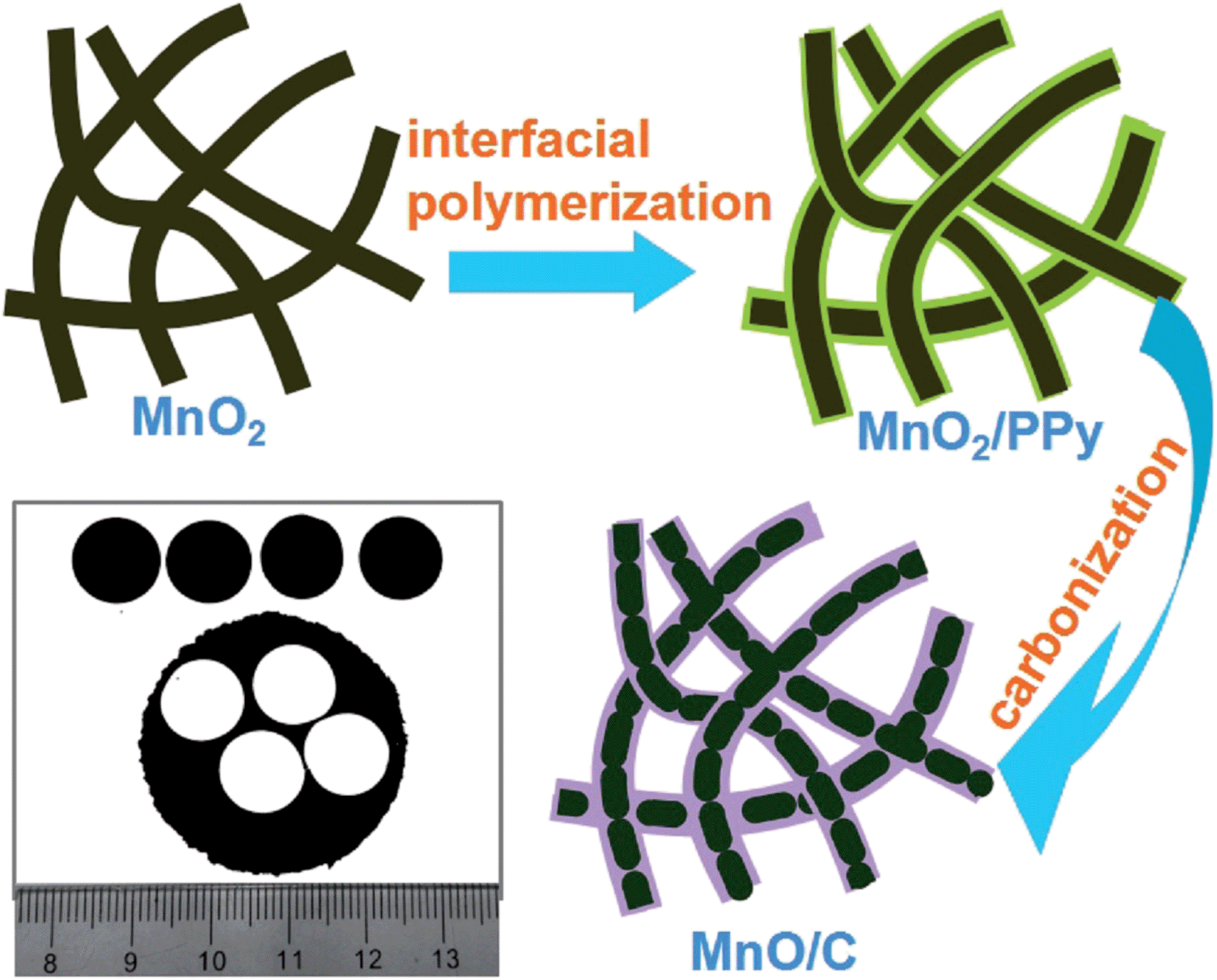 | ||
| Fig. 1 Schematic illustration of synthesis of ultralong MnO/C nanowires and a photograph of the freestanding electrodes punched from the freestanding MnO/C membrane. | ||
2. Experimental section
2.1 Materials synthesis
All of the chemical reagents were of analytical grade and were used as received without purification.2.2 Structure characterization
The phase structures were identified by X-ray powder diffraction analysis (XRD, X'Pert PRO MPD, Philips) with Cu-Kα radiation (λ = 1.5418 Å). The Raman spectrum was recorded on a Renishaw Invia RM200 (England) at room temperature in the spectral range of 200–2000 cm−1. The mass content of the carbon coating was determined using thermogravimetric analysis (TGA, TA instrument SDT-Q600). The morphologies and microstructures of the samples were observed on a field emission scanning electron microscope (FE-SEM, LEO-1530) and a high-resolution transmission electron microscope (HRTEM, FEI Tecnai F30G2). The surface chemistry of the nanocomposites was investigated using X-ray photoelectron spectroscopy (XPS, ESCALAB 250Xi, Thermo Scientific).2.3 Electrochemical measurements
The electrochemical properties were measured using coin-type (CR2032) half cells. The working electrodes (Φ = 13 mm) were punched directly from the as-fabricated MnO/C, MnO, and MnO2 membranes, which were directly used to assemble battery cells. The mass of the electrodes is about 1 mg cm−2. Coil cells were assembled with freestanding electrodes as the working electrodes, metal Li plates as the counter electrodes, Celgard 2320 as the separator, and a solution of 1 M LiPF6 in ethylene carbonate (EC)/dimethyl carbonate (DMC)/diethyl carbonate (DEC) (1![[thin space (1/6-em)]](https://www.rsc.org/images/entities/char_2009.gif) :1:1 by volume) as the electrolyte in an argon-filled glovebox. A Solartron electrochemical workstation (1260 + 1287, England) was employed for obtaining cyclic voltammetry (CV) curves in the range of 0.005–3 V at a rate of 0.2 mV s−1 and electrochemical impedance spectra (EIS) in the frequency range of 100 kHz to 50 mHz at room temperature. The galvanostatic charge/discharge tests were carried out using a Land Battery Testing system (Land, China) at various current densities between the cut-off potentials of 0.01 and 2.50 V vs. Li/Li+.
:1:1 by volume) as the electrolyte in an argon-filled glovebox. A Solartron electrochemical workstation (1260 + 1287, England) was employed for obtaining cyclic voltammetry (CV) curves in the range of 0.005–3 V at a rate of 0.2 mV s−1 and electrochemical impedance spectra (EIS) in the frequency range of 100 kHz to 50 mHz at room temperature. The galvanostatic charge/discharge tests were carried out using a Land Battery Testing system (Land, China) at various current densities between the cut-off potentials of 0.01 and 2.50 V vs. Li/Li+.
3. Results and discussion
An ultralong 1D MnO nanostructure (length > 100 μm) is crucial to achieve the formation of flexible and robust freestanding MnO/C membranes. Hence, it is imperative to maintain the unique ultralong nanostructure during the synthesis processes. A novel but facile method to synthesize ultralong MnO/C coaxial nanowires is employed to avoid breakage of the ultralong MnO2 nanowires when coating carbon layers using a hydrothermal method (Fig. 1).14The core of this strategy is creating uniform PPy coatings on the ultralong MnO2 nanowire surfaces via in situ interfacial polymerization of pyrrole monomers, which is based on the redox reaction between pyrrole monomers and MnO2 because of the high oxidation potential of MnO2 (MnO2 + 4H+ + 2e → Mn2+ + 2H2O, φ(MnO2/Mn2+) = 1.23 V) for polymerizing pyrrole monomers.35,36 This process is totally different from conventional PPy preparation using other oxidants, such as FeCl337 and Na2S2O8,9 which would generate many individual PPy nanoparticles disconnected to MnO2. Due to the reactive MnO2 template, the formation of PPy can only occur at the pyrrole/MnO2 interface, thus easily constructing a core–shell MnO2/PPy nanoconfiguration by controlling the pyrrole/MnO2 ratio. Finally, freestanding membranes consisting of MnO/C coaxial nanowires were obtained after a simple carbonization treatment. Fig. 1 also shows a digital image of the resulting MnO/C membrane, from which four freestanding electrodes were punched out without cracks, suggesting robust mechanical integrity of the membrane.
The as-prepared samples were first investigated using X-ray diffraction (XRD) to examine the phase structures and the resulting patterns are shown in Fig. 2. For the pristine MnO2 precursor, all diffraction peaks can be exclusively indexed to tetragonal α-MnO2 (PDF#81-1947).38 After the carbonization process at 600 °C for 2 h in a flowing nitrogen atmosphere, the α-MnO2 phase was converted to MnO. As shown in the patterns of the annealed products, the diffraction peaks at 2θ around 35.0, 40.7, 58.8, 70.3, and 73.9° can be readily indexed to (111), (200), (220), (311), and (222) reflections of the cubic MnO (PDF#07-0230). No other diffraction peaks are detected, indicating a high purity of the products. In order to confirm the presence of carbon coatings in the MnO/C nanocomposites, the Raman spectrum was recorded. As shown in Fig. S1,† the two broad peaks at 1355 and 1583 cm−1 can be assigned to the D and G bands of carbon.17 The high intensity of the D band suggests disordered carbon structures that possess a large amount of defects. In addition, the fundamental peaks at 567 and 642 cm−1 are characteristic of the Mn–O vibration modes.9,21,34 The carbon content in the MnO/C nanocomposites was determined using thermogravimetric analysis (TGA), as shown in Fig. S2,† the carbon content is calculated to be about 19.8 wt%.
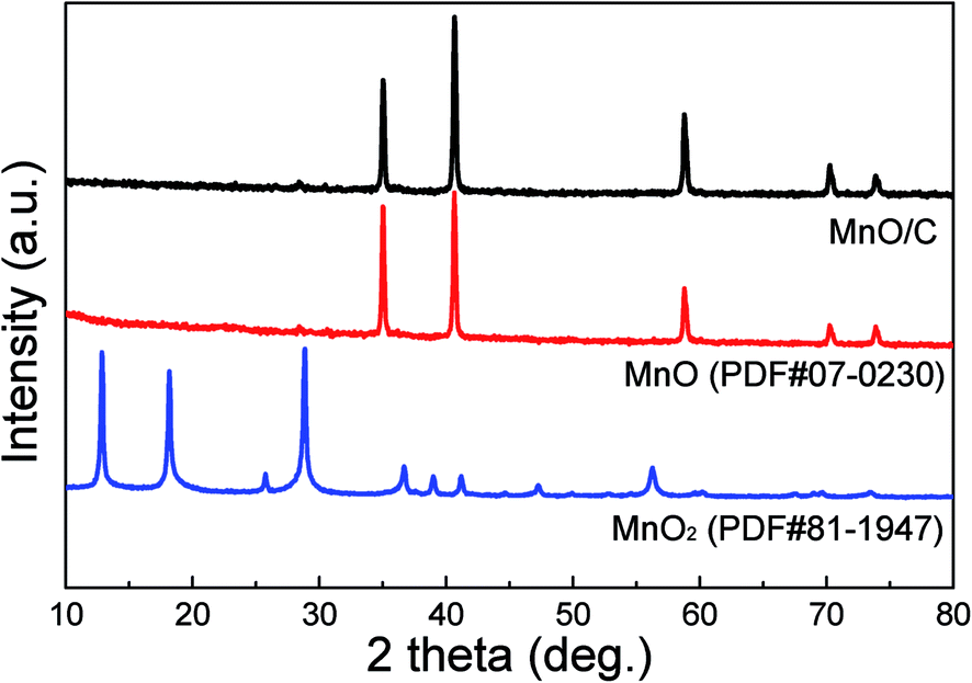 | ||
| Fig. 2 XRD patterns of MnO/C, MnO and MnO2 samples. | ||
The morphology and microstructure of the freestanding MnO2 and MnO/C membranes were characterized using FESEM and TEM. Fig. 3(a) and (b) show the top-view SEM images of the MnO2 membrane (inset shows the optical photograph). The membrane is purely composed of randomly oriented ultralong and straight nanowires with smooth surfaces. The 1D nanowires possess a length of hundreds of micrometers and an average diameter of approximately 100 nm, corresponding to a high aspect ratio of >1000. The nanowires are entangled with each other to construct a robust membrane structure with high porosity and flexibility. A typical TEM image of the MnO2 nanowires is exhibited in Fig. 3(c). The HRTEM image in Fig. 3(d) shows distinct lattice fringes of 0.49 nm in spacing, which agrees well with the interplanar distances of (200) planes of α-MnO2. The corresponding SAED pattern (inset) exhibits well-defined diffraction spots that can be indexed to the α-MnO2 structure. The HRTEM and SAED results also indicate the high quality single crystalline nature of the α-MnO2 nanowires.
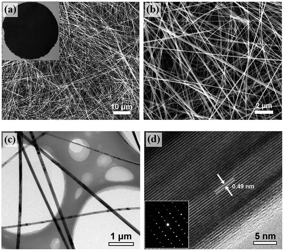 | ||
| Fig. 3 (a–b) SEM images of α-MnO2 nanowires. Inset shows the optical photograph of the membrane. (c) TEM and (d) HRTEM images of α-MnO2 nanowires. Inset shows the corresponding SAED pattern. | ||
After in situ interfacial polymerization of PPy using the MnO2 nanowires as oxidant supports, the surface of the MnO2 nanowires was uniformly coated with PPy layers (Fig. S3†). The subsequent annealing process leads to PPy carbonization and the MnO2 to MnO phase transformation. Fig. 4(a–c) and S4† show the typical morphology of the MnO/C and MnO membranes. The large-scale panoramic view (Fig. 4(a)) indicates that the MnO/C membrane (Fig. 1) possesses a porous architecture consisting of interconnected nanowires. The ultralong nanostructure after annealing is well maintained without breakage (Fig. 4(b and c) and S4†). As shown in Fig. 4(d), each MnO nanowire is enveloped by a uniformly coated carbon layer, constructing a unique coaxial configuration. The diameter of the coaxial nanowires is in the 80–100 nm range and the thickness of the carbon coating layer is about 15 nm (Fig. 4(e)). The HRTEM image in Fig. 4(f) displays clear lattice fringes with a spacing of 0.22 nm, which corresponds to the interplanar distances of the (200) planes of the cubic MnO phase.
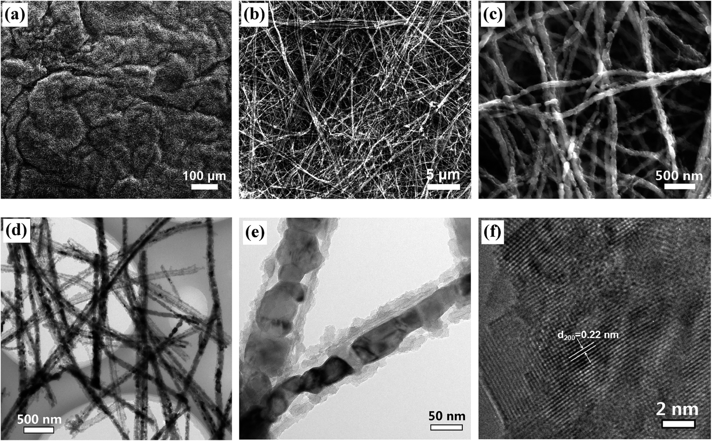 | ||
| Fig. 4 (a–c) SEM images of MnO/C at different magnifications. (d–e) TEM images of MnO/C nanowires. (f) HRTEM image of MnO nanocrystals. | ||
XPS was employed to analyze the surface elements and their electronic states of the MnO/C nanocomposites (Fig. S5†). The survey spectrum (Fig. S5(a)†) confirms the presence of Mn, O, C, and N elements in the product with no trace of impurities. The high-resolution Mn 2p doublet (Fig. S5(b)†) with two peaks located at 641.5 eV for Mn 2p3/2 and 653.2 eV for Mn 2p1/2 is characteristic of MnO.34,39 The oxidation state of Mn in the MnO/C nanocomposites can be determined by analyzing the Mn 3s spectrum. As shown in Fig. S5(c),† the spin energy separation of 5.78 eV demonstrates a Mn valence of +2.40 The C 1s peak (Fig. S5(d)†) can be fitted into four components centered at 284.6, 285.5, 286.4, and 288.1 eV, representing C–C, C–N, C–O–C, and C–O bonds, respectively.21,38,41 The N 1s peak (Fig. S5(e)†) can be resolved into two peaks centered at 398.3 and 400.4 eV, which correspond to hexagonal pyridinic-N (N6) and pentagonal pyrrolic-N (N5), respectively.42–44 A high N6/N5 ratio of 1.26 indicates that a large portion of N atoms within the pyrrole rings is converted to pyridinic-N during the annealing process. More importantly, the sp2 hybridized pyridinic-N can enhance the electronic conductivity of the carbon structure,42,44,45 which is beneficial to improving the electrochemical performance of the MnO/C nanocomposites.
The as-prepared MnO/C nanocomposite membranes were directly used as freestanding anodes for LIBs to investigate their Li-ion storage properties. The electrochemical behavior is first studied using the cyclic voltammetry (CV) method. Fig. 5(a) shows the CV curves of the initial four cycles at a scan rate of 0.2 mV s−1. In the first cathodic sweep, the sharp reduction peak below 0.5 V corresponds to the reduction of Mn2+ to Mn0 and the formation of solid electrolyte interface (SEI) films.18,34,39 From the second cycle, the reduction peak shifts to approximately 0.36 V, which is a reversible phase transformation resulting from the formation of metallic Mn and Li2O. The observed peak centered at 1.35 V in the anodic sweep is attributed to the oxidation of Mn0 to Mn2+. The reversible conversion reaction can be written as follows:
| MnO + 2Li+ + 2e− ↔ Mn + Li2O |
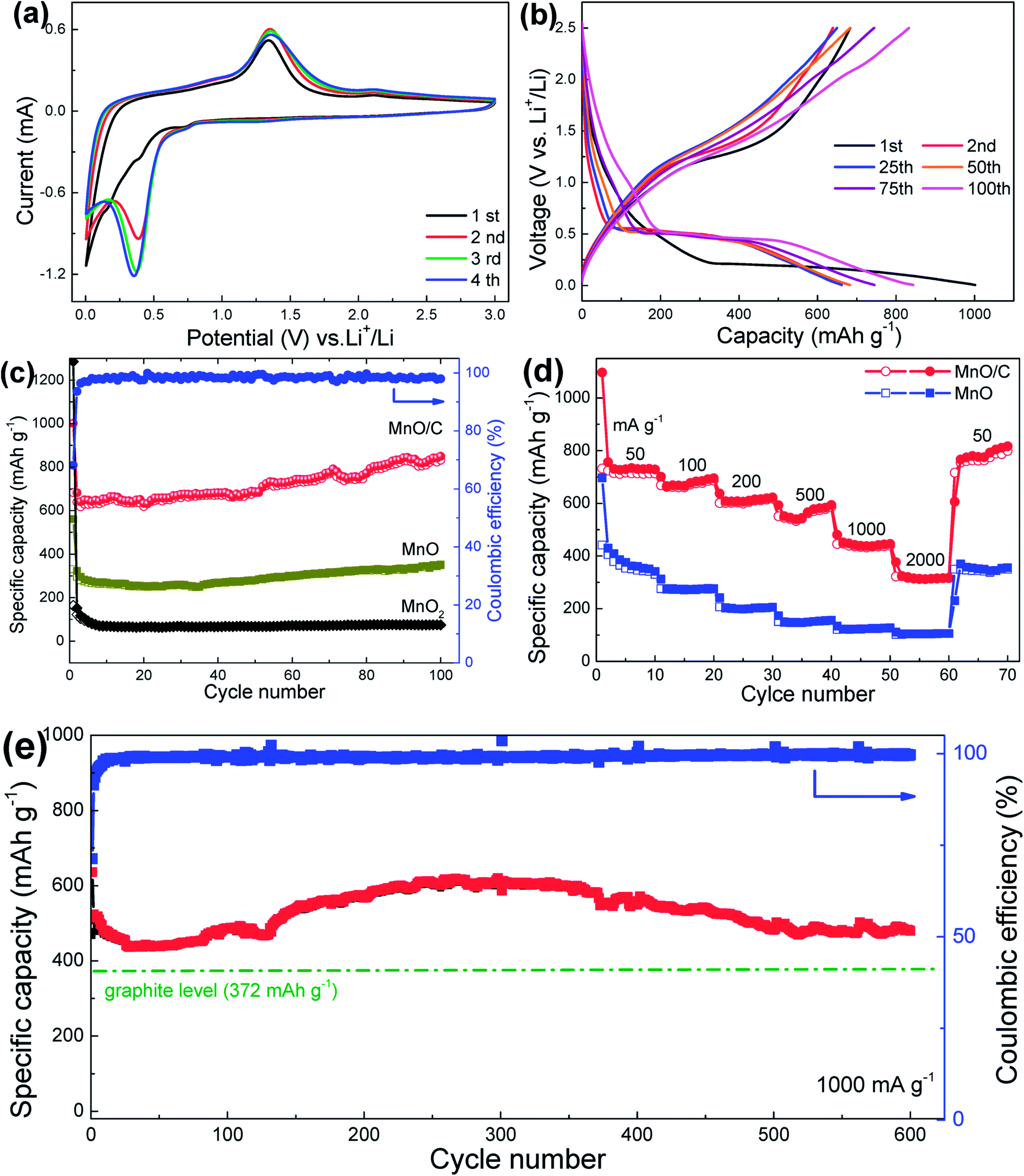 | ||
| Fig. 5 (a) CV curves and (b) galvanostatic charge/discharge profiles of MnO/C anodes. (c) Cycling performance of MnO2, MnO and MnO/C anodes at a current density of 100 mA g−1. (d) Rate capability of MnO and MnO/C anodes. (e) Long-term cycling performance of the MnO/C anode at a current density of 1000 mA g−1. | ||
In addition, the CV curves after the first cycle overlapped well, indicating high reversibility and good electrochemical stability of the freestanding MnO/C anode. Fig. 5(b) shows the charge/discharge voltage profiles of the MnO/C anode at a current density of 100 mA g−1. In the first discharge process, a long voltage plateau at 0.2 V, which is related to the reduction of Mn2+ to Mn, can be observed, and the plateau shifts to about 0.5 V in the second and the onward discharge processes. During the subsequent charge processes, the sloped plateau in the 1.1–1.5 V range is associated with the re-oxidation of Mn to Mn2+. These results are consistent with the CV analysis. It is important to note that the first discharge and charge specific capacity are 1001 and 683 mA h g−1, respectively, revealing an initial Coulombic efficiency of 68.2% that is common for transition metal oxide anodes. The irreversible capacity loss can be ascribed to the inevitable formation of SEI films on the surface of the anode and some irreversible side reactions of Li+ with oxygen-contained functional groups and some special sites in the vicinity of residual H atoms in the carbon structure.43 It should be noted that the initial Coulombic efficiency of the MnO/C anode is much higher than that of control samples, MnO (58.9%) and MnO2 (12.9%), indicating a better electrochemical utilization of MnO enhanced by the conductive carbon coating. Fig. 5(c) compares the cycling performance of the three freestanding anodes. Notably, the MnO/C nanocomposites exhibit a reversible capacity of 832 mA h g−1 after 100 cycles at a current density of 100 mA g−1, which is much higher than those of MnO (349 mA h g−1) and MnO2 (75 mA h g−1). The specific capacity is also higher than the initial values and the theoretical capacity of MnO (755 mA h g−1). The outstanding capacity retention is believed to result from the uniform carbon coating, which renders improved conversion reaction kinetics and higher reaction activities. The improved kinetics of the MnO/C anode upon cycling are mainly attributed to the reduction of the charge-transfer resistance confirmed by electrochemical impedance spectra (EIS) analysis (Fig. S6†). The lower charge-transfer resistance allows a faster Li-reaction with MnO, which enables Mn2+ to be re-oxidized to a higher oxidation state.22 This phenomenon can also be observed in the charge voltage profiles, as shown in Fig. 5(b), the sloped plateau at around 2.1 V becomes more broader upon cycling, indicating an ever-increasing capacity and higher Li-reaction activities that can generate a reversible capacity higher than the theoretical value of MnO.
In addition to the superior capacity, the freestanding MnO/C anode also presents good rate capability. As shown in Fig. 5(d), the MnO/C anode exhibits significantly enhanced rate performance compared to the bare MnO anode. When tested at different current densities of 50 (0.07 C), 100 (0.13 C), 200 (0.26 C), 500 (0.66 C), 1000 (1.32 C), and 2000 mA g−1 (2.65 C), the nanocomposite anode can deliver average reversible capacities of 731, 678, 614, 556, 440, and 315 mA h g−1, respectively. After the high-rate cycling at 2000 mA g−1, the capacity increases to 810 mA h g−1 when the current density is recovered to 50 mA g−1, further implying the excellent reversibility of the MnO/C anode. The better rate capability of the MnO/C anode can be ascribed to the carbon coating, which offers high conductivity for rapid electron collection and migration during the high-rate cycling. The ultralong 1D nanowires further help the conductive carbon coatings to promote long-range charge transference and the membrane offers a porous structure for efficient electrolyte ingress and diffusion throughout the electrode. In addition, the coaxial nanoscale structure can shorten the ion/electron transport distance to boost the reaction kinetics. The EIS comparison among the three anodes (Fig. S7†) clearly demonstrates that the MnO/C anode has the smallest charge-transfer resistance compared with the control anodes, indicating better reaction kinetics.
To further investigate the long-cycle stability of the MnO/C anodes operated at high-rates, the MnO/C anodes were measured at high current densities of 500 and 1000 mA g−1 for 400 and 600 cycles, respectively, as shown in Fig. S8† and 5(e). It demonstrates that the MnO/C anode can deliver a specific capacity of 480 mA h g−1 after 600 charge/discharge cycles at 1000 mA g−1 with a Coulombic efficiency of over 98% (initial efficiency: 71.3%), similarly, a specific capacity of 597 mA h g−1 is retained after 400 cycles at 500 mA g−1. The remarkable high-rate cycling stability can primarily be ascribed to the typical surface carbon coating, which functions as a resilient barrier to accommodate the volume expansion/contraction of MnO during the lithiation/delithiation processes and to preclude the agglomeration of the coaxial nanostructures upon cycling. In addition, the freestanding architecture can provide high mechanical strength to maintain the structural integrity of the electrode.
In addition to the overall excellent electrochemical performance of the freestanding MnO/C anode, it is worth mentioning that the capacity results reported here are calculated based on the total mass of the freestanding electrodes. As mentioned earlier, the electrochemically inactive components of extra binders, conductive additives and in particular current collectors account for at least 50 wt% of a conventional electrode fabricated with powder-like nanomaterials. When taking all of these inactive components into consideration, the freestanding MnO/C nanocomposite would be much more fascinating in terms of gravimetric energy density and electrode fabrication (time saving). In addition, the specific capacity of the MnO/C anode during the high-rate 600-cycle test at 1000 mA g−1 (1.32 C, Fig. 5(e)) is not only much higher than the theoretical value (372 mA h g−1) of the commercial graphite anode, but also superior to other freestanding MnOx/C nanocomposites, such as MnOx/sing-walled CNT (437 mA h g−1 at 800 mA g−1),28 Mn3O4/super-aligned CNT (465 mA h g−1 at 1 C),7 MnO2/graphene (305 mA h g−1 at 800 mA g−1),29 MnOx/CNF (420 mA h g−1 at 500 mA g−1),31 and MnOx/CNF (255 mA h g−1 at 500 mA g−1).32 Together with the facile synthesis procedures, the long-term cycling performance promises the freestanding MnO/C nanocomposite to be a potential anode material for practical applications.
4. Conclusions
Freestanding membranes consisting of ultralong MnO/C coaxial nanowires have successfully been fabricated using a hydrothermal method followed by in situ interfacial polymerization of PPy and a carbonization process. The ultralong 1D nanostructure and the uniform carbon coating collectively enable the as-fabricated freestanding MnO/C anodes to exhibit excellent lithium-storage properties in terms of specific capacity, rate capability, and particularly cycling stability. The electrochemical evaluations indicate that the freestanding MnO/C anode can deliver a high specific capacity of 832 mA h g−1 at 100 mA g−1 after 100 cycles. More significantly, even after a long-term 600-cycle test at a high current rate of 1000 mA g−1, the anode retains a reversible capacity of 480 mA h g−1. The remarkable electrochemical performance demonstrates that the freestanding MnO/C nanocomposite holds great potential as a promising anode material for advanced LIBs. Furthermore, the present synthesis strategy paves a new avenue for fabricating freestanding LIB electrodes based on other transition metal oxide nanostructures.Acknowledgements
The authors acknowledge the financial support of this work from the National Natural Science Foundation of China (51402236, 53102219 and 51472204), the National Natural Science Foundation of Shannxi Province (2015JM5180), the Fundamental Research Funds for the Central Universities (3102014JCQ01020), and the Program of Introducing Talents of Discipline to Universities (B08040), the Specialized Research Fund for the Doctoral Program of Higher Education of China (20136102140001 and 20136102120024). BQW is grateful for the financial support from the US National Science Foundation (1067960).References
- T.-H. Kim, J.-S. Park, S. K. Chang, S. Choi, J. H. Ryu and H.-K. Song, Adv. Energy Mater., 2012, 2, 860–872 CrossRef CAS PubMed.
- M. Armand and J.-M. Tarascon, Nature, 2008, 451, 652–657 CrossRef CAS PubMed.
- V. Etacheri, R. Marom, R. Elazari, G. Salitra and D. Aurbach, Energy Environ. Sci., 2011, 4, 3243–3262 CAS.
- M. V. Reddy, G. V. S. Rao and B. V. R. Chowdari, Chem. Rev., 2013, 113, 5364–5457 CrossRef CAS PubMed.
- L. Ji, Z. Lin, M. Alcoutlabi and X. Zhang, Energy Environ. Sci., 2011, 4, 2682–2699 CAS.
- P. Poizot, S. Laruelle, S. Grugeon, L. Dupont and J. Tarascon, Nature, 2000, 407, 496–499 CrossRef CAS PubMed.
- S. Luo, H. Wu, Y. Wu, K. Jiang, J. Wang and S. Fan, J. Power Sources, 2014, 249, 463–469 CrossRef CAS PubMed.
- X. Li, S. Xiong, J. Li, X. Liang, J. Wang, J. Bai and Y. Qian, Chem.–Eur. J., 2013, 19, 11310–11319 CrossRef CAS PubMed.
- X. Gu, J. Yue, L. Chen, S. Liu, H. Xu, J. Yang, Y. Qian and X. Zhao, J. Mater. Chem. A, 2015, 3, 1037–1041 CAS.
- B. Sun, Z. Chen, H.-S. Kim, H. Ahn and G. Wang, J. Power Sources, 2011, 196, 3346–3349 CrossRef CAS PubMed.
- X. Li, Y. Zhu, X. Zhang, J. Liang and Y. Qian, RSC Adv., 2013, 3, 10001–10006 RSC.
- L. Su, Y. Zhong, J. Wei and Z. Zhou, RSC Adv., 2013, 3, 9035–9041 RSC.
- C. Wang, L. Yin, D. Xiang and Y. Qi, ACS Appl. Mater. Interfaces, 2012, 4, 1636–1642 CAS.
- G.-L. Xu, Y.-F. Xu, H. Sun, F. Fu, X.-M. Zheng, L. Huang, J.-T. Li, S.-H. Yang and S.-G. Sun, Chem. Commun., 2012, 48, 8502–8504 RSC.
- Y. Ding, C. Wu, H. Yu, J. Xie, G. Cao, T. Zhu, X. Zhao and Y. Zeng, Electrochim. Acta, 2011, 56, 5844–5848 CrossRef CAS PubMed.
- L. Li, C. Nan, J. Lu, Q. Peng and Y. Li, Chem. Commun., 2012, 48, 6945–6947 RSC.
- X. Zhang, Z. Xing, L. Wang, Y. Zhu, Q. Li, J. Liang, Y. Yu, T. Huang, K. Tang and Y. Qian, J. Mater. Chem., 2012, 22, 17864–17869 RSC.
- Y. Sun, X. Hu, W. Luo and Y. Huang, J. Mater. Chem., 2012, 22, 19190–19195 RSC.
- A. L. M. Reddy, M. M. Shaijumon, S. R. Gowda and P. M. Ajayan, Nano Lett., 2009, 9, 1002–1006 CrossRef CAS PubMed.
- H. Xia, M. Lai and L. Lu, J. Mater. Chem., 2010, 20, 6896–6902 RSC.
- K. Zhang, P. Han, L. Gu, L. Zhang, Z. Liu, Q. Kong, C. Zhang, S. Dong, Z. Zhang and J. Yao, ACS Appl. Mater. Interfaces, 2012, 4, 658–664 CAS.
- Y. Sun, X. Hu, W. Luo, F. Xia and Y. Huang, Adv. Funct. Mater., 2013, 23, 2436–2444 CrossRef CAS PubMed.
- H. Wang, L.-F. Cui, Y. Yang, H. Sanchez Casalongue, J. T. Robinson, Y. Liang, Y. Cui and H. Dai, J. Am. Chem. Soc., 2010, 132, 13978–13980 CrossRef CAS PubMed.
- Y. Mai, D. Zhang, Y. Qiao, C. Gu, X. Wang and J. Tu, J. Power Sources, 2012, 216, 201–207 CrossRef CAS PubMed.
- W.-M. Chen, L. Qie, Y. Shen, Y.-M. Sun, L.-X. Yuan, X.-L. Hu, W.-X. Zhang and Y.-H. Huang, Nano Energy, 2013, 2, 412–418 CrossRef CAS PubMed.
- C. Chae, J. H. Kim, J. M. Kim, Y.-K. Sun and J. K. Lee, J. Mater. Chem., 2012, 22, 17870–17877 RSC.
- Z. Li, N. Liu, X. Wang, C. Wang, Y. Qi and L. Yin, J. Mater. Chem., 2012, 22, 16640–16648 RSC.
- J. Qin, Q. Zhang, Z. Cao, X. Li, C. Hu and B. Wei, Nano Energy, 2013, 2, 733–741 CrossRef CAS PubMed.
- A. Yu, H. W. Par, A. Davies, D. C. Higgins, Z. Chen and X. Xiao, J. Phys. Chem. Lett., 2011, 2, 1855–1860 CrossRef CAS.
- L. Ji and X. Zhang, Electrochem. Commun., 2009, 11, 795–798 CrossRef CAS PubMed.
- L. Ji, A. J. Medford and X. Zhang, J. Mater. Chem., 2009, 19, 5593–5601 RSC.
- Z. Lin, L. Ji, M. D. Woodroof and X. Zhang, J. Power Sources, 2010, 195, 5025–5031 CrossRef CAS PubMed.
- B. Liu, X. Hu, H. Xu, W. Luo, Y. Sun and Y. Huang, Sci. Rep., 2013, 4, 4299 Search PubMed.
- Y. Xiao, X. Wang, W. Wang, D. Zhao and M. Cao, ACS Appl. Mater. Interfaces, 2014, 6, 2051–2058 CAS.
- J.-G. Wang, B. Wei and F. Kang, RSC Adv., 2014, 4, 199–202 RSC.
- J.-G. Wang, Y. Yang, Z.-H. Huang and F. Kang, Electrochim. Acta, 2014, 130, 642–649 CrossRef CAS PubMed.
- J. Li, L. Cui and X. Zhang, Appl. Surf. Sci., 2010, 256, 4339–4343 CrossRef CAS PubMed.
- B. Lan, L. Yu, T. Lin, G. Cheng, M. Sun, F. Ye, Q. Sun and J. He, ACS Appl. Mater. Interfaces, 2013, 5, 7458–7464 CAS.
- Y. Xia, Z. Xiao, X. Dou, H. Huang, X. Lu, R. Yan, Y. Gan, W. Zhu, J. Tu, W. Zhang and X. Tao, ACS Nano, 2013, 7, 7083–7092 CrossRef CAS PubMed.
- M. Toupin, T. Brousse and D. Bélanger, Chem. Mater., 2004, 16, 3184–3190 CrossRef CAS.
- L. Qie, W. Chen, H. Xu, X. Xiong, Y. Jiang, F. Zou, X. Hu, Y. Xin, Z. Zhang and Y. Huang, Energy Environ. Sci., 2013, 6, 2497–2504 Search PubMed.
- D. Nan, Z.-H. Huang, R. Lv, L. Yang, J.-G. Wang, W. Shen, Y. Lin, X. Yu, L. Ye, H. Sun and F. Kang, J. Mater. Chem. A, 2014, 2, 19678–19684 CAS.
- L. Qie, W.-M. Chen, Z.-H. Wang, Q.-G. Shao, X. Li, L.-X. Yuan, X.-L. Hu, W.-X. Zhang and Y.-H. Huang, Adv. Mater., 2012, 24, 2047–2050 CrossRef PubMed.
- W. H. Shin, H. M. Jeong, B. G. Kim, J. K. Kang and J. W. Choi, Nano Lett., 2012, 12, 2283–2288 CrossRef CAS PubMed.
- H. M. Jeong, J. W. Lee, W. H. Shin, Y. J. Choi, H. J. Shin, J. K. Kang and J. W. Choi, Nano Lett., 2011, 11, 2472–2477 CrossRef CAS PubMed.
Footnote |
| † Electronic supplementary information (ESI) available: Raman spectrum and TGA curve of the MnO/C composite; TEM images of MnO2/PPy; SEM images of MnO; XPS spectra of MnO/C; EIS curves of the MnO/C anode in the fresh state and after 100 cycles. EIS curves of MnO/C, MnO and MnO2 electrodes. Cycling performance of the MnO/C anode at 500 mA g−1. See DOI: 10.1039/c5ta02440d |
| This journal is © The Royal Society of Chemistry 2015 |