
 Open Access Article
 This Open Access Article is licensed under a
 Creative Commons Attribution 3.0 Unported Licence
Novel phosphoric acid-doped PBI-blends as membranes for high-temperature PEM fuel cells
Florian
Mack
 a,
Karin
Aniol
b,
Corina
Ellwein
b,
Jochen
Kerres
*bc and
Roswitha
Zeis
a
a,
Karin
Aniol
b,
Corina
Ellwein
b,
Jochen
Kerres
*bc and
Roswitha
Zeis
a
aKarlsruhe Institute of Technology (KIT), Helmholtz Institute Ulm (HIU), Ulm, Germany
bUniversity of Stuttgart, Institute of Chemical Process Engineering, University of Stuttgart, Stuttgart, Germany. E-mail: jochen.kerres@icvt.uni-stuttgart.de
cNorth-West University, Potchefstroom Campus, Chemical Resource Beneficiation, Potchefstroom, South Africa
First published on 13th April 2015
Abstract
Novel acid–base blend membranes for application in high-temperature polymer electrolyte membrane fuel cells (HT-PEMFCs) were synthesized and characterized. The acid–base blend membranes demonstrated high thermal and excellent chemical stabilities in terms of oxidative weight loss. Small changes in the molecular weight distribution after immersion in Fenton's solution were determined with gel permeation chromatography (GPC). Scanning electron microscope (SEM) images showed the outstanding integrity of the acid–base blend membranes after a 24 hour-long Fenton's test. In contrast to pure polybenzimidazole (PBI) and AB-PBI membranes the new acid–base membranes exhibited long-term stability in phosphoric acid (PA) at 130 °C. Ionic cross-linking between acid and base blend polymers improved the stability and integrity of the membranes. The in situ conductivities of several acid–base blend membranes were higher than that of pure AB-PBI membranes with drastically reduced acid uptake. Membrane electrode assemblies (MEAs) based on these blend membranes were prepared showing good fuel cell performance at practical relevant operation conditions. This study proves that acid–base blends are a suitable alternative to pure PBI and AB-PBI as membranes for HT-PEMFCs.
1 Introduction
PA-doped PBI for use in HT-PEMFCs (100–220 °C) can be traced back to the work of Savinell et al.1 The advantage of PA-doped PBI membranes lies in the conductivity mechanism: in these membranes PA overtakes the proton transport instead of water2 which widens the temperature range of fuel cell membranes to the abovementioned temperature range, in which membranes which need water as a vehicle for H+ transport (such as Nafion® or other sulfonated membranes) do not work anymore due to dry-out. A disadvantage of the PBI–PA composite membranes is the possible bleeding-out of PA from the membrane in cases where the operation temperature falls below 100 °C, where condensed water flushes out PA from the membrane,3 as proven by in situ tests with neutron tomography.4 The operation limits of this membrane have been investigated by taking into account the PA bleeding-out problem.5 The so-released PA can cause strong corrosion damage within the fuel cell system.A further disadvantage of PA-doped PBI is the chemical degradation of the polymer in the fuel cell,6 which is mainly relevant in the temperature range 150–200 °C, which is required for minimizing of carbon monoxide (CO) poisoning of the anode catalyst.
Within the last decade several approaches have been investigated to improve the stability of PBI. Strategies include the preparation of base–excess acid–base blend membranes of PBI with acidic polymers in which the acidic blend component acts as macromolecular ionic cross-linker for the blend membrane by proton transfer from the acidic group onto the basic imidazole sites of the PBI. Such membranes have been a research and development topic in the group of one of the authors of this study for more than a decade.7
It could be shown that the base–excess acid–base PBI blend membranes exhibit better chemical stabilities than pure PBI membranes as determined by Fenton's test (FT), where the membranes are subjected to oxidative treatment with an aqueous 3% H2O2 solution also containing 4 ppm of Fe2+ ions, which catalyze the decay of H2O2 into OH˙ radicals that attack the polymer chains.8,9 It could also be shown that the introduction of ionical cross-links into the PBI membranes can prevent them from dissolution in PA during the doping procedure.10
In the study presented here novel PBI–excess acid–base blend membranes have been investigated in terms of their chemical stabilities and in terms of their performance in an HT-PEMFC at an operation temperature of 160 °C. The different polymer compounds forming the PBI-blend membranes are depicted in Fig. 1. In Table 1, the composition of the different blend membranes, their thickness and type of crosslinking are shown.
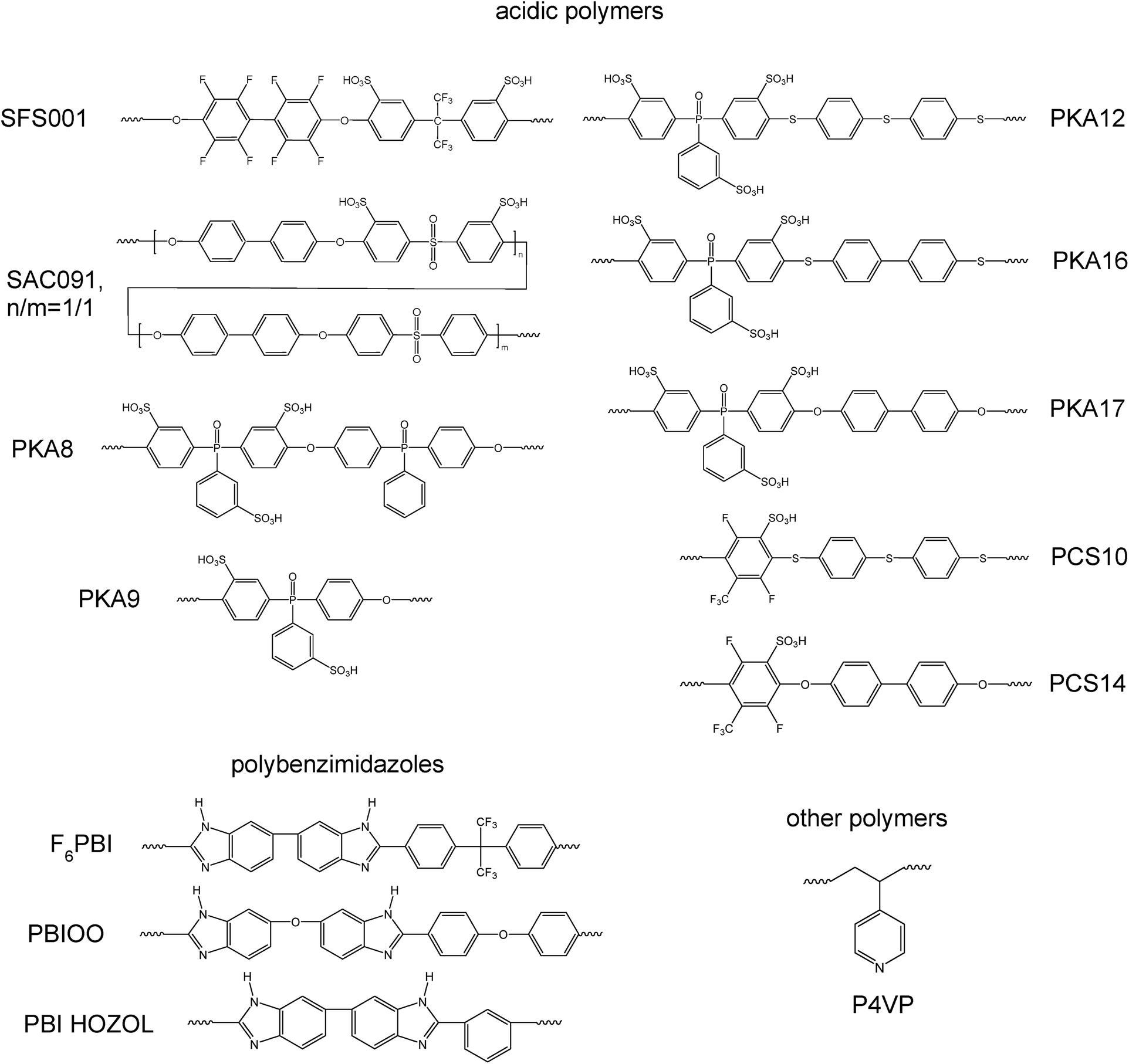 | ||
| Fig. 1 Polymers used for the preparation of the blend membranes. | ||
| Membrane | Polybenzimidazoles | wt% | Acidic polymer | wt% | Thickness/μm | Cross-linking |
|---|---|---|---|---|---|---|
| a Additive: diiododecane. b Base–base blend membrane. c Poly(4-vinylpyridine), basic polymer. | ||||||
| MJK1844a,b | F6PBI | 67 | P4VPc | 33 | 55 | Covalently |
| MJK1845 | F6PBI | 70 | SFS001 | 30 | 100 | Ionically |
| MJK1846 | PBIOO | 70 | SAC091 | 30 | 100 | Ionically |
| MCS8X | PBIOO | 70 | PCS10 | 30 | 68 | Ionically |
| MCS8Y | PBIOO | 60 | PCS10 | 40 | 56 | Ionically |
| MCS8Z | PBIOO | 50 | PCS10 | 50 | 48 | Ionically |
| MKA015 | F6PBI | 70 | PKA9 | 30 | 51 | Ionically |
| MKA016 | F6PBI | 70 | PKA12 | 30 | 46 | Ionically |
| MKA017 | F6PBI | 70 | PKA17 | 30 | 40 | Ionically |
| MKA018 | F6PBI | 70 | PKA8 | 30 | 77 | Ionically |
| MKA050 | F6PBI | 70 | PKA16 | 30 | 43 | Ionically |
| PCS141 | PBI HOZOL | 70 | PCS14 | 30 | 64 | Ionically |
In Fig. 2, the covalent cross-linking at the blend membrane MJK1844 is shown, and in Fig. 3 the ionical cross-linking at the base–excess acid–base blend membranes at the example of the membrane MJK1845.
 | ||
| Fig. 2 Covalent cross-linking at the membrane MJK1844. | ||
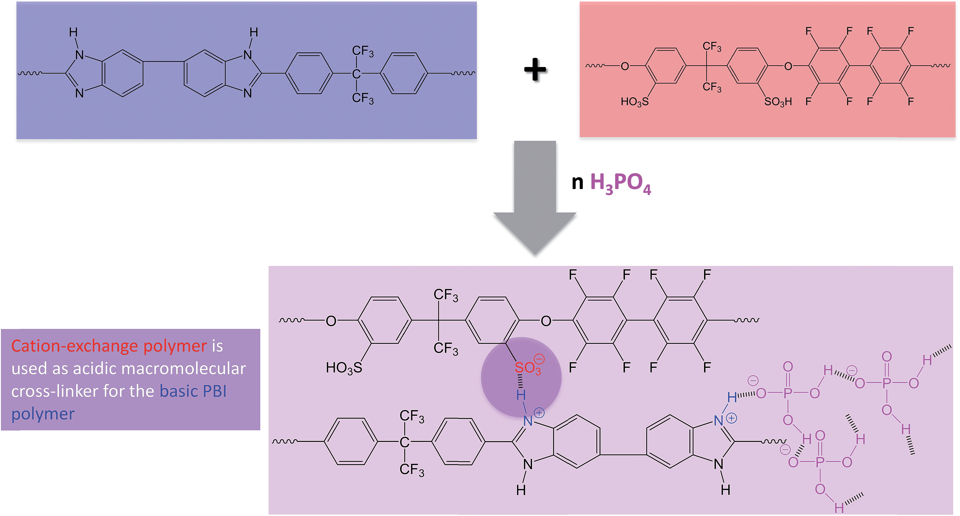 | ||
| Fig. 3 Ionical cross-linking and formation of the hydrogen bridge network by PA doping of the membrane MJK1845 as an example for the ionically cross-linked blend membranes. | ||
2 Experimental
2.1 Thermal stability
The thermal stability of the membranes was measured with thermogravimetry (TGA) using a Netzsch STA 449C Jupiter with a heating rate of 20 K min−1 under an oxygen enriched atmosphere (65–70% oxygen, 30–35% nitrogen).The decomposition gases were examined with a coupled FTIR spectrometer (Nicolet Nexus) to determine the start of the backbone degradation (CO evolution). The splitting-off temperature of the sulfonic acid group was identified through the asymmetric stretching vibration of the S![[double bond, length as m-dash]](https://www.rsc.org/images/entities/char_e001.gif) O group at 1352–1342 cm−1.
O group at 1352–1342 cm−1.
2.2 Oxidative stability
The oxidative stability of the membranes was determined with FT. The undoped membranes were immersed in a Fenton's solution consisting of 3 wt% hydrogen peroxide containing 4 ppm Fe2+ (added as FeSO4) for a period of 24–144 hours at 68 °C.8 Afterwards, the membrane samples were collected by filtering, washed with water, dried at 90 °C and weighed.The molecular weight (MW) distribution of the polymers was measured by GPC using an Agilent Technologies GPC system (series 1200) with a light scattering detector (static light scattering detector SLD7000) combined with a refractive index detector (Shodex RI71) for the concentration signal. MW of the polymers was directly obtained from the light scattering detector signal. For the GPC analysis, 2 wt% solutions of the polymers in dimethylacetamide (DMAc) were prepared, and 5 g L−1 LiBr was added to the polymer solutions prior to the measurements. Toluene was also added to the solvent to correct reversible changes in the column system. The molar mass distribution was measured with a constant flow rate of 1 ml min−1 at 60 °C.
The physical deterioration of the membranes was determined with SEM. Before the SEM measurements the samples were dried at 100 °C for 14 h and subsequently sputtered with gold for 3 minutes. The SEM pictures were obtained with a CamScan CS44 SEM.
2.3 Membrane doping and electrode preparation
The synthesis of the blend membranes was described previously.8 Commercial available AB-PBI membranes were purchased from Fuma-Tech (fumapem AM). The membranes were dried over night at 90 °C and afterwards their thickness was measured. Subsequently, the membranes were doped with PA by immersion in concentrated PA (85%, Carl Roth) at 130 °C until their weight was constant. Additional PA on top of the membranes was removed with a paper towel before weighing. The amount of acid in the membranes was determined gravimetrically.Catalyst suspensions (catalyst inks) containing water (Millipore), isopropanol, polytetrafluoroethylene (PTFE) solution (60%, 3 M), and 20% Pt/C (Heraeus) were used for the gas diffusion electrode (GDE) preparation. The catalyst ink was sprayed in multiple layers directly onto the microporous layer of the gas diffusion layer (H2315 C2, Freudenberg) at a substrate temperature of 80 °C. The catalyst loading was kept constant at 1 mg cm−2, which was calculated from the weight difference between the dried GDE and the gas diffusion layer. All the GDEs had approximately the same PTFE content of 10% by weight. The GDE preparation was described in detail previously.11
2.4 Electrochemical characterization
The membrane electrode assemblies (MEAs) were prepared by placing the GDEs in direct contact with the doped membranes in single cells without hot-pressing. The single cells with an active area of 4 cm2 included gaskets (PTFE from Bohlender), sub-gaskets (PEEK from Victrex), metallic bipolar plates with single serpentine flow-fields (1 mm × 1 mm in dimension) and aluminum plates equipped with heating cartridges. The cell measurements were done at 160 °C and ambient pressure using dry hydrogen and air as reactants. Stoichiometric mass flows of hydrogen (λ = 1.4) and air (λ = 2) were used for current densities equal to or above 200 mA cm−2. Gas flows were fixed for current densities below 200 mA cm−2. Polarization curves were recorded by increasing the current density stepwise from zero (open circuit) up to 800 mA cm−2 or until the cell potential dropped below 300 mV. Cell internal resistances were determined by measuring AC impedances at 1 kHz with an MR2212W impedance meter (Schuetz Messtechnik).3 Results and discussion
3.1 Thermal stability
The thermal stability of the membranes was determined by TGA-FTIR-coupling to determine the starting temperatures for the separation of the sulfonic acid groups and the polymer backbone degradation (CO evolution). The TGA traces of the acid–base blend membranes MJK1845 and MJK1846 in Fig. 4 show a similar behavior up to 400 °C apart from an initial water loss of the MJK1846 membrane. The thermal stability of the base–base blend membrane MJK1844 was drastically lower. The acid–base blend membranes were stabilized by ionic cross-linking.9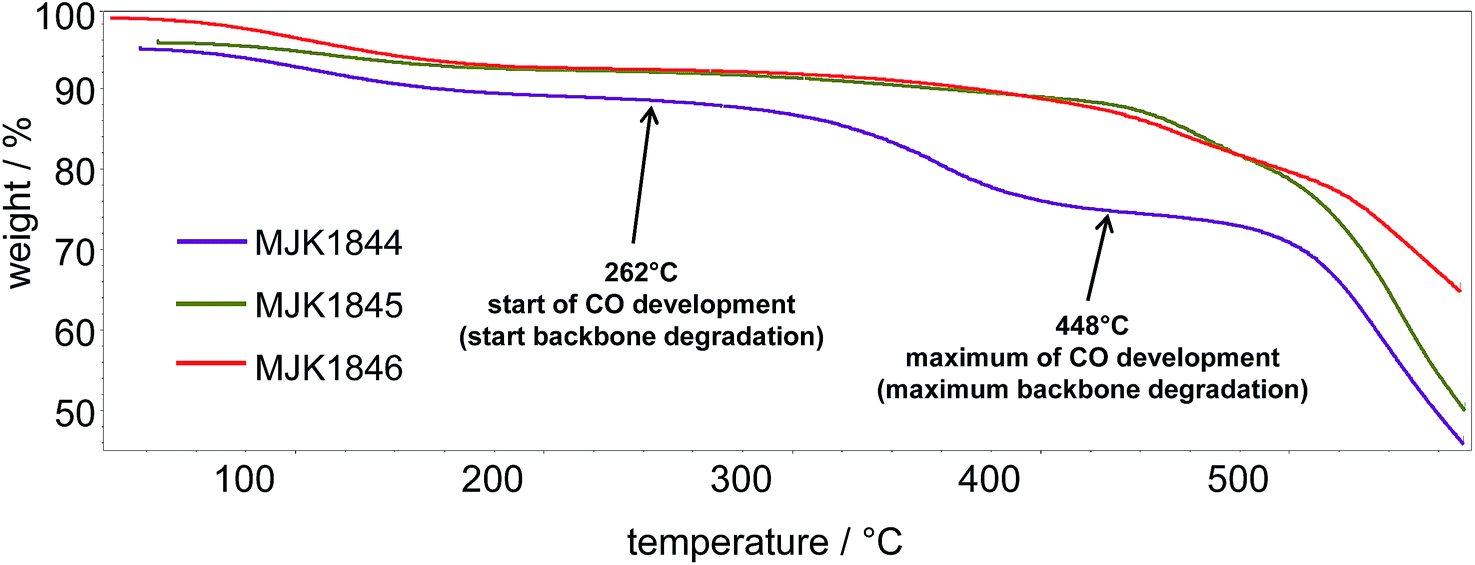 | ||
| Fig. 4 TGA traces of the MJK membranes. | ||
A comparison of the onset temperatures of the SO3H splitting off and the backbone degradation of the membranes is presented in Table 2. The ionically cross-linked acid–base blend membranes demonstrate high thermal stability, especially the MCS and PCS membranes.
| Membrane | T SO3H/°C | T backbone/°C |
|---|---|---|
| MCS8X | 397 | 490 |
| MCS8Y | 410 | 481 |
| MCS8Z | 379 | 483 |
| MJK1844 | — | 262 |
| MJK1845 | 284 | 315 |
| MJK1846 | 304 | 407 |
| PCS141 | 430 | 460 |
| PBI14 | — | 500 |
3.2 Oxidative stability
High chemical stability is a crucial requirement for fuel cell membranes. The oxidative stability of the membranes was tested with FT, and changes in the weight loss, the MW distribution, and the physical properties of the membranes were determined. The most common degradation mechanism described in literature is the attack of the polymer chain by in situ formed hydroxyl and hydroperoxyl radicals. This leads to a reduction of the polymer weight9,12 and the breakdown of the polymer backbone into small pieces, which are dissolved in the Fenton's solution.13An alternative mechanism is the separation of sulfonic acid groups. Both mechanisms drastically reduce the mechanical stability of the membranes which is crucial for fuel cell application.
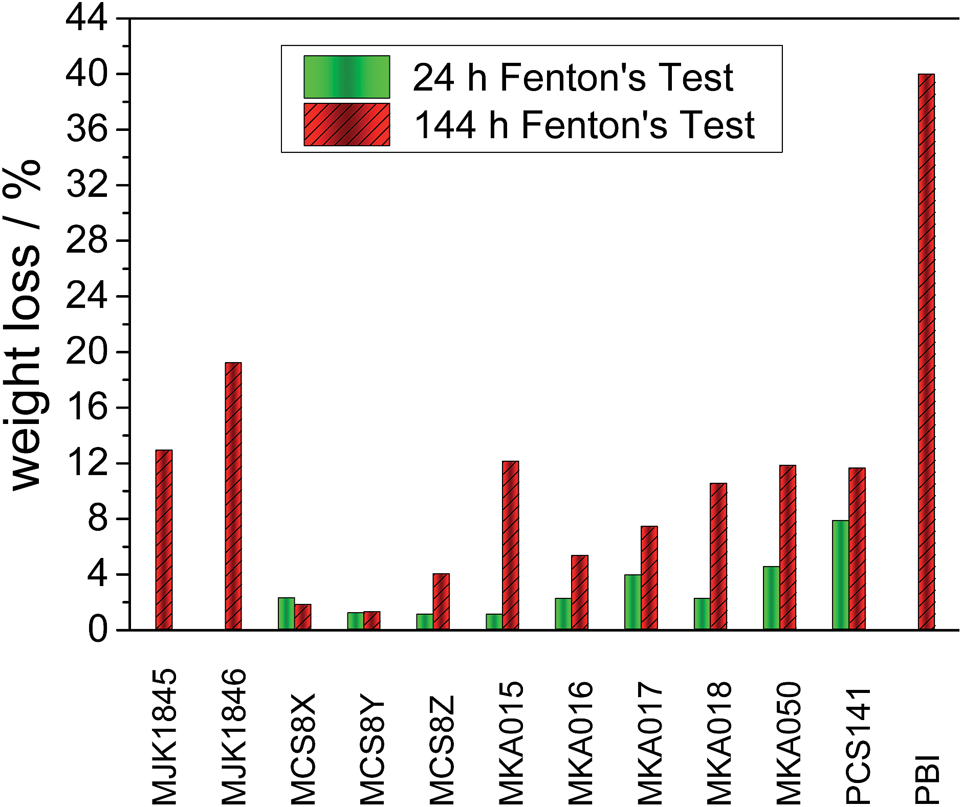 | ||
| Fig. 5 Weight loss of the acid–base blend membranes and PBI20 after 24 and 144 hours Fenton test. | ||
The low weight loss of the MCS membranes can be explained with the partially fluorinated polymer PCS10 as acidic blend polymer. The binding energy of C–F bonds is higher than for C–H bonds,15 and PCS10 does not contain ether bridges, which are vulnerable to radical attacks.16 The pure basic blend polymers show a drastically higher stability than the pure acidic blend polymers.17 Therefore stable acidic polymers are crucial for robust blend membranes.
Compared to pure PBI18 or AB-PBI19 membranes with weight losses of up to 80% all investigated acid–base blend membranes show drastically reduced weight losses during the FT. The cross-linking network improves the stability of the acid–base blend membranes which was already observed for other blend membranes.9,20
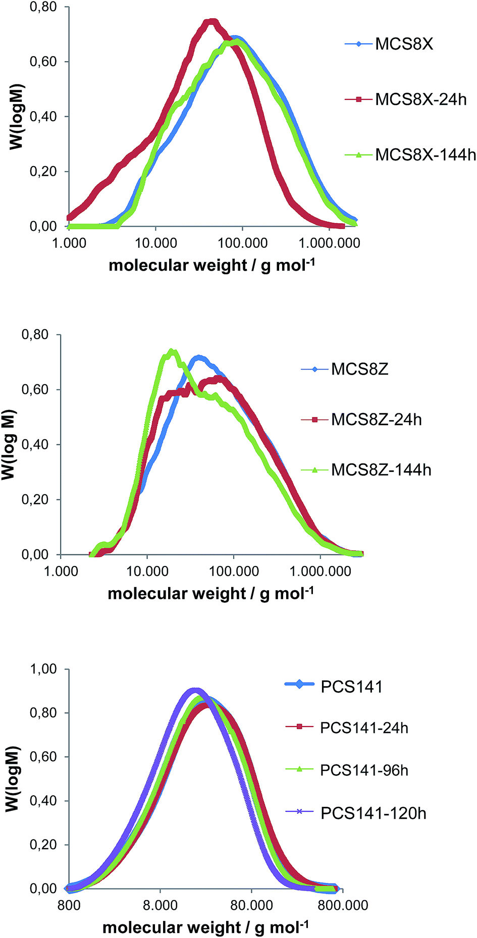 | ||
| Fig. 6 M W distribution of the membranes MCS8X, MCS8Z and PCS141 before and after different durations of Fenton test. | ||
The average MW of the membrane MCS8X decreased after 24 hours FT; however it increased again after 144 hours FT. A possible explanation is the splitting of the polymer chains and the formation of polymer radicals during the first 24 hours FT, which led to a reduction of the MW. The polymer radicals remained in the membrane and recombined, which resulted in a higher MW after 144 hours FT. An alternative explanation is the degradation of the polymer chains into smaller molecules which initially remain in the membrane and are gradually washed out with proceeding time in the Fenton's solution. After the dissolution of the smaller polymer pieces the average MW increases again. The MW loss of the membrane MCS8Z was about 20![[thin space (1/6-em)]](https://www.rsc.org/images/entities/char_2009.gif) 000 g mol−1 after 144 hours FT, which is comparable to similar blend membranes9 and much lower than for pure PBIOO.17 The MW distribution of the PCS141 membrane was almost constant during the first 96 hours FT and decreased slightly after 120 hours FT. The results of the GPC measurements from the MKA membranes are presented in Fig. 7 and compared with the initial MW distribution of the basic blend polymer F6PBI.
000 g mol−1 after 144 hours FT, which is comparable to similar blend membranes9 and much lower than for pure PBIOO.17 The MW distribution of the PCS141 membrane was almost constant during the first 96 hours FT and decreased slightly after 120 hours FT. The results of the GPC measurements from the MKA membranes are presented in Fig. 7 and compared with the initial MW distribution of the basic blend polymer F6PBI.
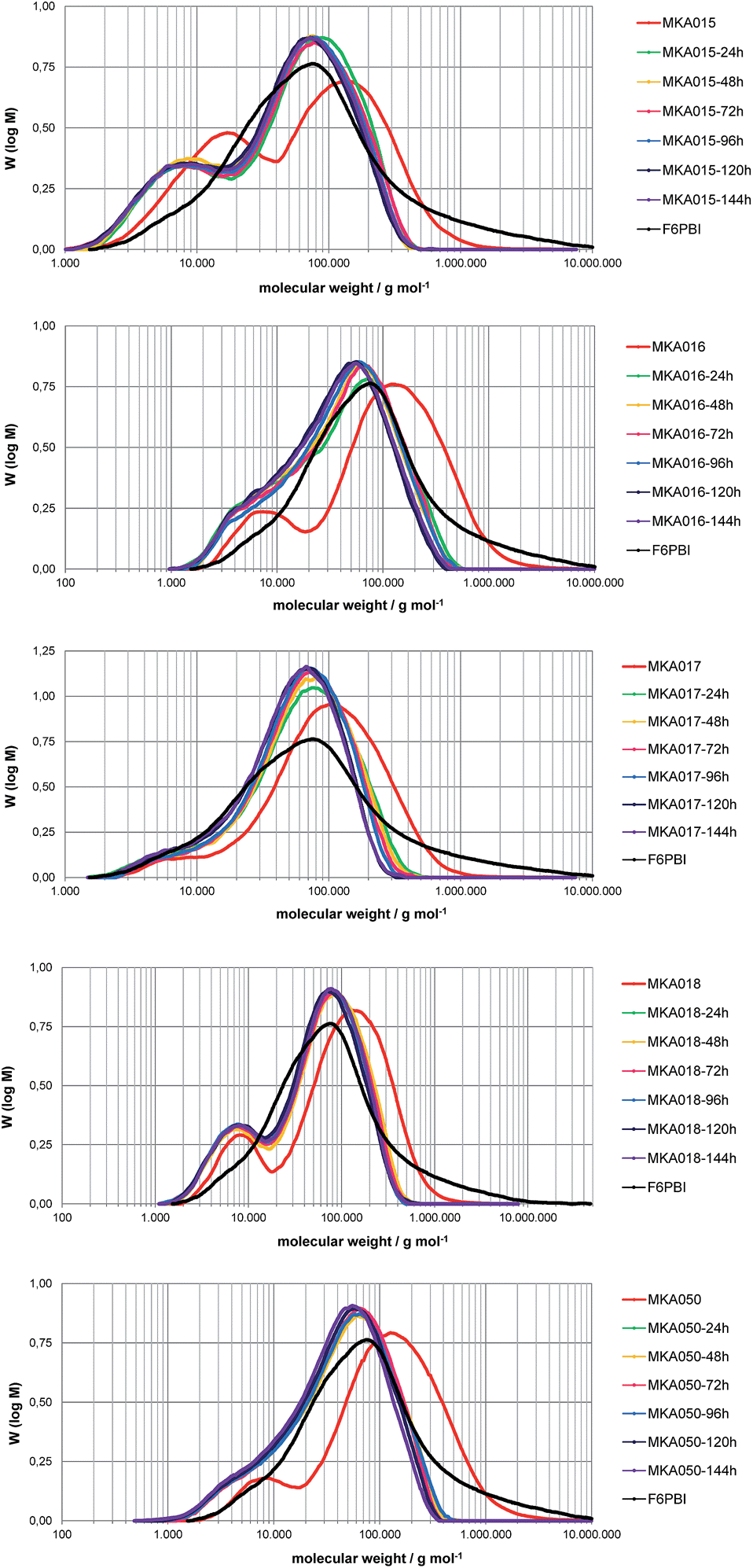 | ||
| Fig. 7 M W distribution of the MKA membranes before and after different durations of Fenton test. | ||
The average MW of the MKA membranes strongly decreased during the first 24 hours FT and between 24 and 144 hours the MW distribution was almost similar. The higher maximum of the MW distribution curve is approximately at the same MW as the maximum of the MW distribution of pure F6PBI. The degradation seems to be mainly focused on the acidic blend polymers. The basic polymer is quite resistant due to its very stable perfluoroisopropylidene bridges,21 the radical-trapping properties of the imidazole group9 and the ionic cross-linking network17 which maintains the membrane integrity.
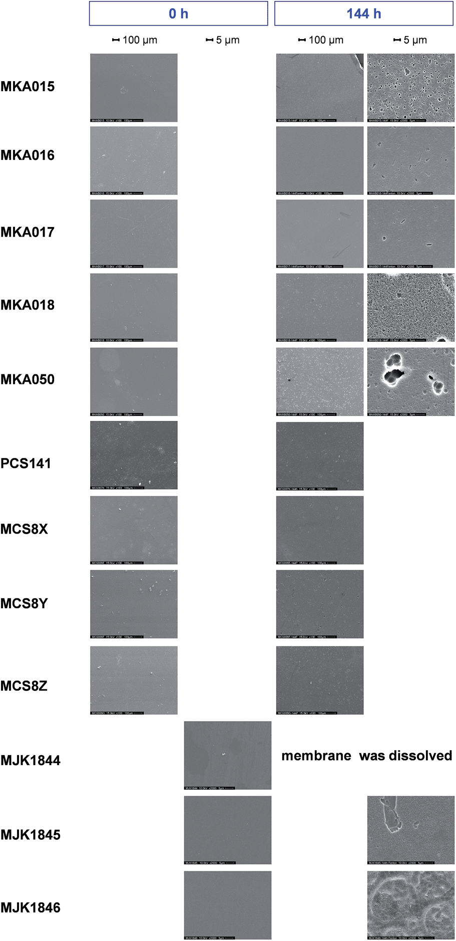 | ||
| Fig. 8 SEM images of the membranes before and after 144 hours Fenton test; magnification 100×/2000×. | ||
After 144 hours FT, the MJK1844 membrane was dissolved and the surfaces of the acid–base blend membranes exhibited small holes in the range of 1 to 5 μm in diameter. Pure PBI membranes strongly degraded during the first 24 hours of FT and exhibited significant holes in the membrane in contrast to the blend membranes.13 AB-PBI membranes exhibited cracks over the whole membrane surface after 24 hours FT, and therefore demonstrated less chemical stability than the investigated acid–base blend membranes.19
3.3 Acid uptake and doping time
Pure PBI membranes can be doped by immersion in a concentrated aqueous PA solution at room temperature. After about 48 hours the equilibrium is reached with a doping level of 5–6 mol PA per repeating unit of PBI.22 Higher doping levels increase the membrane conductivity; however the mechanical strength is weakened.23Cross-linked blend membranes require higher doping temperatures because at room temperature the acid uptake is negligible. Fig. 9 shows the weight increase of the cross-linked membranes after immersion in PA at 130 °C until the weight was constant.
 | ||
| Fig. 9 Phosphoric acid uptake of the membranes by weight; T = 130 °C (120 °C for AB-PBI). | ||
As reference the acid uptake of a commercial AB-PBI membrane (fumapem AM, Fumatech) after a previously optimised doping process (6 h, 120 °C) is presented. In contrast to the blend membranes, the AB-PBI membrane partly dissolved at 130 °C, and the colour of the acid changed into slightly brown which resulted in low mechanical strength and decreased membrane conductivity.24 The acid–base blend membranes are stabilized by the ionic cross-linking network.
Except of the covalently cross-linked base–base blend membrane MJK1844, the acid uptake of the blend membranes was lower as for the AB-PBI membrane despite the higher doping temperature. The comparison of the membranes MCS8X, MCS8Y and MCS8Z containing 50–70% of the basic polymer PBIOO shows that the doping level correlates with the base content in the membrane. The reduction of the PBIOO content from 70% to 50% halves the acid uptake. Nevertheless the acidic polymer also has a major influence on the doping level as can be seen from the MKA membranes, which all contain 70% F6PBI though with different acidic polymers.
The required doping times to reach the equilibrium of the PA uptake are presented in Fig. 10. The doping time of almost all blend membranes was drastically shorter than that of AB-PBI. Except of the MJK1846 and the MKA018 membranes, the doping time of the blend membranes was a maximum of 2 hours. The covalently cross-linked base–base blend membrane MJK1844 reached a weight increase of almost 500% in 30 minutes due to the high amount of free basic nitrogen atoms in the polymer.
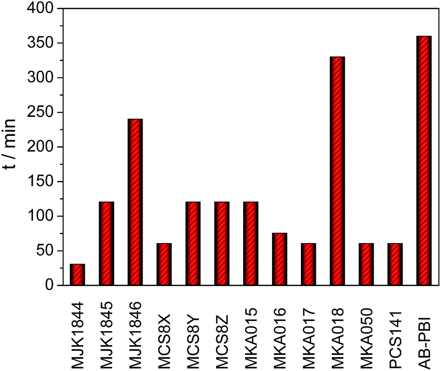 | ||
| Fig. 10 Doping time until membrane weight was constant. | ||
3.4 High frequency resistance and specific resistance
The high frequency resistance (HFR) of the MEAs was measured in situ during fuel cell operation. The thickness of the membranes used for the MEA preparation was different, which is a critical parameter for IR losses in a fuel cell. Therefore the specific resistance (HFR divided by membrane thickness) of the membranes was calculated and is shown along with HFR in Fig. 11. The lowest HFR and specific resistance was achieved with the membranes MKA015 and MCS8Y.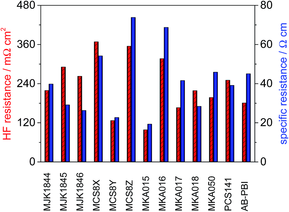 | ||
| Fig. 11 High frequency resistance and specific resistance of the membranes; T = 160 °C, A = 2.56 cm2, 1 mg Pt cm−2, hydrogen/air with λ = 1.4/2, j = 200 mA cm−2. | ||
The comparison between the relative HFR and specific resistance of the membranes shows that the HFR of the membranes MCS8Z, MKA016, MKA017, MKA050 and AB-PBI benefits from the relative low membrane thickness and especially the HFR of the membranes MJK1845 and MJK1846 is relatively high due to the higher membrane thickness.
In contrast to pure PBI membranes25 there was no direct correlation between the specific resistance and the PA uptake of the blend membranes. This might be due to the fact that PA-doped PBI-type HT-PEMFC membranes are very complex systems in which not only the absolute PA content is of importance, but also the PA distribution within the membrane matrix.24
As an example for the complex dependence of membrane properties from membrane composition, a literature example is mentioned here: for cross-linked anion-exchange membranes from electrospun nanofibers it was observed that there is a complex interplay between swelling, cross-linking degree and ion conductivity:26 when the cross-linking degree of the membranes was increased, first their ionic conductivity increased because the membrane swelling was decreased, leading to a higher content of fixed charge groups per unit volume of water, although the ionomer fiber ion-exchange capacity (IEC), which is calculated at the basis of dry ionomer, decreased with the increase of cross-linking degree. Only after overstepping a particular cross-linking degree, the conductivity began to decrease.
In case of the MKA membranes which contain phosphin oxide building groups it was observed that the P O groups are good proton acceptors and therefore able to form strong hydrogen bonds,27,28 which could be responsible for the observed high PA doping degree of the MKA015. MEAs based on the membranes with the highest acid uptake (MJK1844 and AB-PBI) only showed average specific resistance values among the investigated membranes.
The amount of acidic and basic polymers in the membranes had a major influence on the specific resistance. The specific resistance of the membrane MCS8Y consisting of 60% PBIOO and 40% PCS10 was about three times lower than the specific resistance of the membranes MCS8X (70% PBIOO, 30% PCS10) and MCS8Z (50% PBIOO, 50% PCS10). It turns out that for the unexpected behaviour of these membranes many different and in part counteracting properties of the ternary membranes PBI/sulfonated polymer/PA are responsible, among them mass ratio between PBI and sulfonated polymer, type of PBI and of sulfonated polymer, ionical cross-linking density of blend membrane, hydrophilicity of the blend-forming polymers, distribution of PA in the membranes, interactions between PA and polymer chain segments of the blend components, making prediction of the ternary membrane properties in dependence of these factors very difficult.
For clarification of the interplay between composition and properties of these membranes, many parameters of the membranes such as type of PBI, type and sulfonation degree of the sulfonated polymer, mass ratio between PBI and sulfonated blend component, PA doping degree, membrane thickness, and operation temperature would have to be varied. This is however beyond the scope of the present study which included screening of different PBI–excess acid–base blend membranes in terms of their suitability for application in HT-PEMFC application as a substitute for pure PBI membranes.
3.5 Fuel cell performance
The MEA performance is crucial for the application of membranes in fuel cells. Normalized application-oriented operation parameters were used for the cell tests to obtain comparable and practical relevant results. All MEAs were made of the particular membrane doped with PA and two electrodes consisting of 90% carbon supported platinum catalyst and 10% PTFE binder. The polarization curves, which are presented in Fig. 12, were measured at 160 °C and stoichiometries of 1.4 (hydrogen) and 2 (air). To simplify the comparison of the fuel cell performance, the measured current density at a cell potential of 500 mV was extracted from the polarisation curves and is shown along with the HFR in Fig. 13.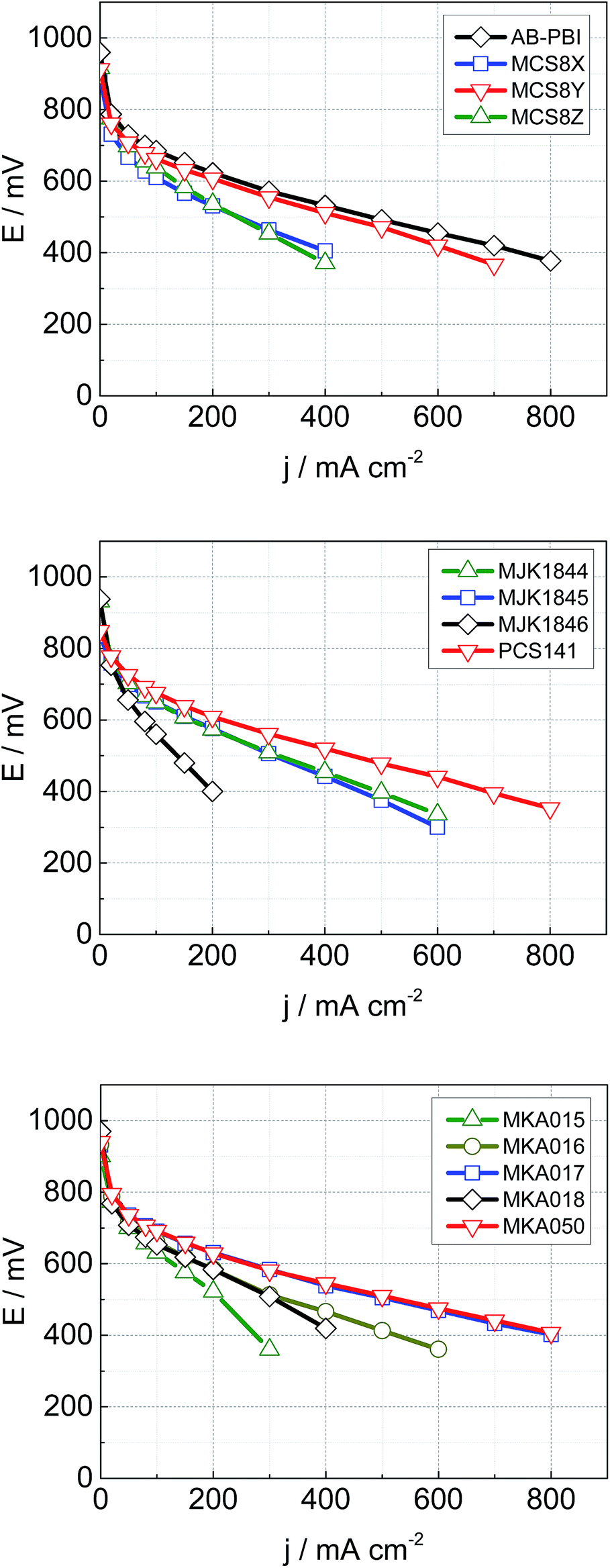 | ||
| Fig. 12 Cell performance of MEAs with different membranes; T = 160 °C, A = 4 cm2, 1 mg Pt cm−2, λ (hydrogen) = 1.4, λ (air) = 2, ambient pressure. | ||
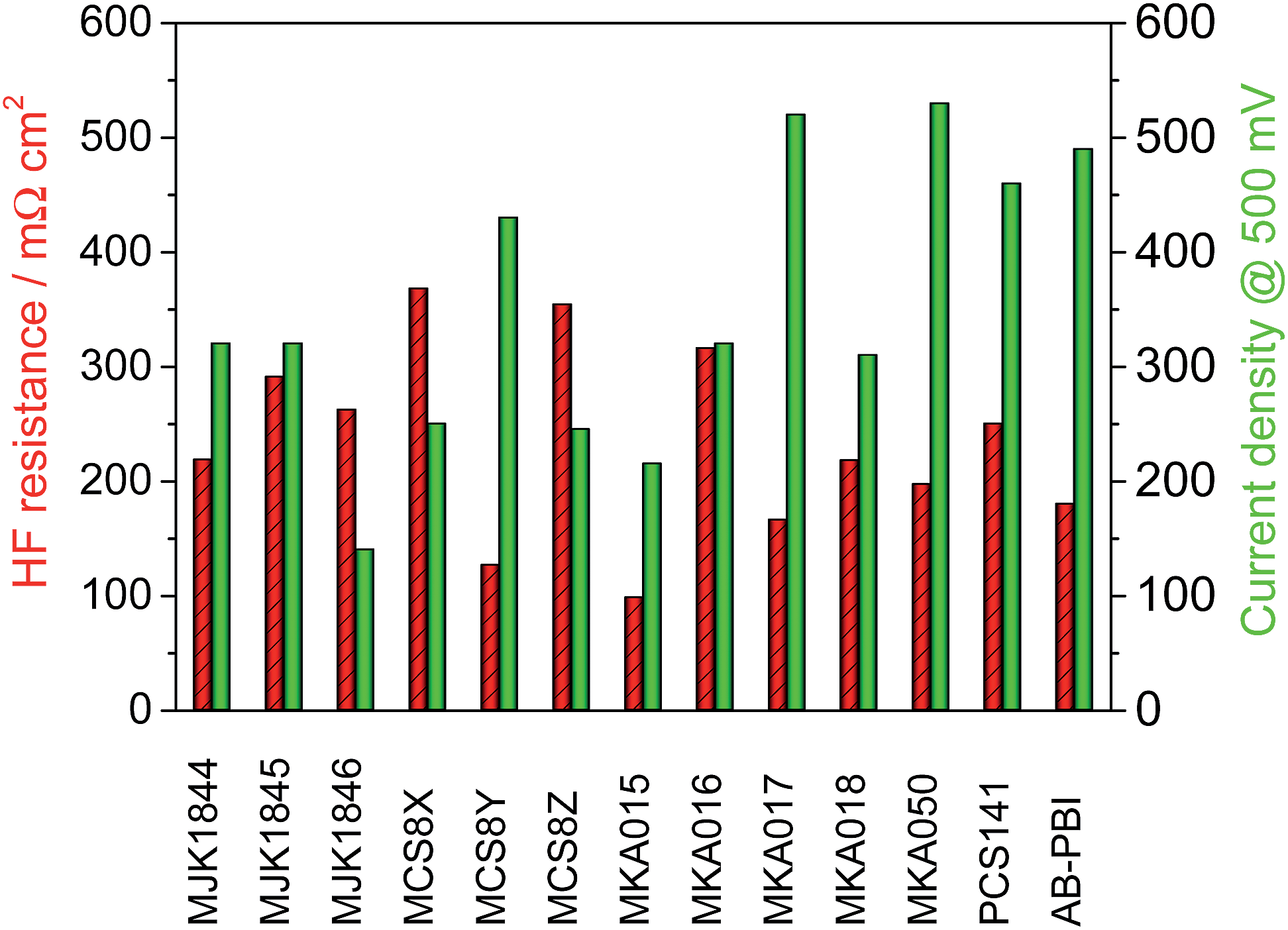 | ||
| Fig. 13 High frequency resistance of the membranes and current density of the MEAs at 500 mV; T = 160 °C, A = 2.56 cm2, 1 mg Pt cm−2, hydrogen/air with λ = 1.4/2. | ||
The acid–base blend membranes MCS8Y, MKA017, MKA050, PCS141 and the AB-PBI membrane showed the highest MEA performance. The high MEA performance of the MCS8Y membrane can be explained with its very low HFR and the membranes with the highest HFR, MCS8X, MCS8Z and MKA016, showed a low MEA performance. However; no principal correlation between low HFR and high performance was observed.
The membranes MKA015 and MKA018 showed a low MEA performance despite low to average HFR values. The stiffness of both membranes was very high, even after doping with PA, which made it difficult to attach the electrodes to the membranes. This could have decreased the interface between membrane and electrodes leading to an increased charge-transfer resistance.
The polarisation curve of the membrane MKA015 showed a potential drop at 300 mA cm−2 which indicated a mass transport problem in the electrodes. This is often caused by PA flooding of the electrodes and a simultaneous concentration decrease of the PA concentration in the surface layer of the membrane which might increase the interface resistance between membrane and electrodes and therefore lead to the observed potential drop of the polarization curve. Such behaviour might be prevented by adjusting the PTFE content in the electrodes.29,30
The base–base blend membrane MJK1844 had the highest PA uptake after the shortest doping time which indicates that the doping temperature was too high for this membrane. Pure PBI dissolved in PA at a doping temperature of 130 °C and partial dissolution of AB-PBI membranes at these doping conditions was observed in a previous study, leading to reduced MEA performance.24 Optimizing of doping time and temperature similar to studies with AB-PBI membranes24 probably improves the MEA performance of the membrane MJK1844.
The thickness of the membranes MJK1845 and MJK1846 was relatively high compared to the other investigated membranes which led to high HFR despite low specific resistance values (Fig. 11).
4 Conclusions
In this study, novel acid–base blend membranes from the polybenzimidazoles F6PBI, PBIOO and PBI HOZOL for application in HT-PEMFCs were synthesized and characterized. The blend membranes showed good thermal stability and drastically improved chemical stability compared to pure PBI and AB-PBI by means of weight loss during FT. Only small changes in the molecular weight distribution after immersion for 144 hours in Fenton's solution were detected with GPC. SEM images proved the outstanding integrity of the acid–base blend membranes.Ionical cross-linking between the acid and base polymers not only enhanced the chemical stability but also the integrity of the membranes in hot PA. This resulted in higher conductivity of the blend membranes while maintaining reduced swelling. For example, the HF resistances of the blend membranes MCS8Y and MKA017 were lower than that of pure AB-PBI membranes although the acid uptake of the blend membranes was drastically reduced.
MEAs based on the novel blend membranes were prepared and evaluated in single cell tests at practical relevant conditions. The MEAs showed comparable fuel cell performance to state-of-the-art AB-PBI based MEAs for HT-PEMFCs despite the fact that the electrodes were not optimized for the novel blend membranes.
This study proves that acid–base blends are a suitable alternative to pure PBI and AB-PBI as membranes for HT-PEMFCs. In future work the electrodes for the MEAs based on the blend membranes will be optimized to achieve higher cell performance than PBI or AB-PBI based MEAs. Particular attention will be given to the development of novel catalyst layers containing the blend polymers as binder to improve the three-phase interlayer and the acid distribution in the electrodes.
Moreover, for the blend membranes MKA017, MKA050 and PCS141, which exhibited the best fuel cell performance, a detailed investigation of dependence of fuel cell performance from following parameters will be conducted: mass relation between PBI and sulfonated polymer and therefore ionic cross-linking degree, PA doping degree, membrane thickness, and operation temperature. It is expected that the results from this in-depth study will lead to a better understanding between composition and properties of PBI-based HT-PEMFC membranes.
Acknowledgements
The authors would like to acknowledge the financial support of the Impuls und Vernetzungsfonds der Helmholtz Gesellschaft (Young Investigator Group project VH-NG-616) and the DFG (Deutsche Forschungsgemeinschaft – German Research Foundation) under project number KE 673/11-1 and Inna Kharitonova and Galina Schumski for the characterization work on the membranes.References
- J. S. Wainright, J.-T. Wang, D. Weng, R. F. Savinell and M. Litt, J. Electrochem. Soc., 1995, 142, L121–L123 CrossRef CAS PubMed.
- K.-D. Kreuer, S. J. Paddison, E. Spohr and M. Schuster, Chem. Rev., 2004, 104, 4637–4678 CrossRef CAS.
- S. Yu, L. Xiao and B. C. Benicewicz, Fuel Cells, 2008, 8, 165–174 CrossRef CAS PubMed.
- R. Kuhn, J. Scholta, P. Krüger, C. Hartnig, W. Lehnert, T. Arlt and I. Manke, J. Power Sources, 2011, 196, 5231–5239 CrossRef CAS PubMed.
- J. Scholta, R. Kuhn, S. Wazlawik and L. Jörissen, ECS Trans., 2009, 17, 325–333 CAS.
- J. H. Liao, Q. F. Li, H. C. Rudbeck, J. O. Jensen, A. Chromik, N. J. Bjerrum, J. Kerres and W. Xing, Fuel Cells, 2011, 11, 745–755 CrossRef CAS PubMed.
- J. Kerres, A. Ullrich, F. Meier and T. Häring, Solid State Ionics, 1999, 125, 243–249 CrossRef CAS.
- J. Kerres, F. Schönberger, A. Chromik, T. Häring, Q. Li, J. O. Jensen, C. Pan, P. Noyé and N. J. Bjerrum, Fuel Cells, 2008, 8, 175–187 CrossRef CAS PubMed.
- Q. F. Li, H. C. Rudbeck, A. Chromik, J. O. Jensen, C. Pan, T. Steenberg, M. Calverley, N. J. Bjerrum and J. Kerres, J. Membr. Sci., 2010, 347, 260–270 CrossRef CAS PubMed.
- J. A. Kerres, A. Katzfuß, A. Chromik and V. Atanasov, J. Appl. Polym. Sci., 2014, 131 DOI:10.1002/app.39889 , article first published online: 18 SEP 2013.
- F. Mack, M. Klages, J. Scholta, L. Jörissen, T. Morawietz, R. Hiesgen, D. Kramer and R. Zeis, J. Power Sources, 2014, 255, 431–438 CrossRef CAS PubMed.
- A. Panchenko, H. Dilger, E. Möller, T. Sixt and E. Roduner, J. Power Sources, 2004, 127, 325–330 CrossRef CAS PubMed.
- Z. Chang, H. Pu, D. Wan, L. Liu, J. Yuan and Z. Yang, Polym. Degrad. Stab., 2009, 94, 1206–1212 CrossRef CAS PubMed.
- Q. Li, J. O. Jensen, R. F. Savinell and N. J. Bjerrum, Prog. Polym. Sci., 2009, 34, 449–477 CrossRef CAS PubMed.
- Q. Li, R. He, J. O. Jensen and N. J. Bjerrum, Chem. Mater., 2003, 15, 4896–4915 CrossRef CAS.
- J. Lawrence and T. Yamaguchi, J. Membr. Sci., 2008, 325, 633–640 CrossRef CAS PubMed.
- A. Chromik and J. A. Kerres, Solid State Ionics, 2013, 252, 140–151 CrossRef CAS PubMed.
- M. Han, G. Zhang, Z. Liu, S. Wang, M. Li, J. Zhu, H. Li, Y. Zhang, C. M. Lew and H. Na, J. Mater. Chem., 2011, 21, 2187 RSC.
- J. J. Linares, C. Sanches, V. A. Paganin and E. R. González, J. Electrochem. Soc., 2012, 159, F194–F202 CrossRef CAS PubMed.
- Q. Li, C. Pan, J. O. Jensen, P. Noyé and N. J. Bjerrum, Chem. Mater., 2007, 19, 350–352 CrossRef CAS.
- H. Pu, L. Wang, H. Pan and D. Wan, J. Polym. Sci., Part A: Polym. Chem., 2010, 48, 2115–2122 CrossRef CAS PubMed.
- Q. Li, R. He, J. O. Jensen and N. J. Bjerrum, Fuel Cells, 2004, 4, 147–159 CrossRef CAS PubMed.
- Q. Li, J. O. Jensen, C. Pan, V. Bandur, M. S. Nilsson, F. Schönberger, A. Chromik, M. Hein, T. Häring, J. Kerres and N. J. Bjerrum, Fuel Cells, 2008, 8, 188–199 CrossRef CAS PubMed.
- F. Mack, S. Heissler, R. Laukenmann and R. Zeis, J. Power Sources, 2014, 270, 627–633 CrossRef CAS PubMed.
- S. Bose, T. Kuila, T. X. H. Nguyen, N. H. Kim, K. Lau and J. H. Lee, Prog. Polym. Sci., 2011, 36, 813–843 CrossRef CAS PubMed.
- A. M. Park, F. E. Turley, R. J. Wycisk and P. N. Pintauro, Macromolecules, 2014, 47, 227–235 CrossRef CAS.
- S. Wang, Q. Ji, C. N. Tchatchoua, A. R. Shultz and J. E. Mcgrath, J. Polym. Sci., Part B: Polym. Phys., 1999, 37, 1849–1862 CrossRef CAS.
- S. Wang, J. Wang, Q. Ji, A. R. Shultz, T. C. Ward and J. E. McGrath, J. Polym. Sci., Part B: Polym. Phys., 2000, 38, 2409–2421 CrossRef CAS.
- F. Mack, T. Morawietz, R. Hiesgen, D. Kramer and R. Zeis, ECS Trans., 2013, 58, 881–888 CrossRef PubMed.
- R. Zeis, Beilstein J. Nanotechnol., 2015, 6, 68–83 CrossRef CAS PubMed.
| This journal is © The Royal Society of Chemistry 2015 |