 Open Access Article
Highly oriented BaTiO3 film self-assembled using an interfacial strategy and its application as a flexible piezoelectric generator for wind energy harvesting†
Tao
Gao
a,
Jianjun
Liao
a,
Jianshu
Wang
a,
Yingqiang
Qiu
a,
Quan
Yang
a,
Min
Zhang
a,
Yang
Zhao
c,
Lifeng
Qin
c,
Hao
Xue
*ab,
Zhaoxian
Xiong
ab,
Lifu
Chen
a and
Qing-ming
Wang
*d
aDepartment of Materials Science and Engineering, College of Materials, Xiamen University, Xiamen 361005, China. E-mail: xuehao@xmu.edu.cn
bKey Laboratory of Electronic Ceramic Materials and Components (Xiamen University), Xiamen City, 361005, China
cDepartment of Mechanical and Electrical Engineering, Xiamen University, Xiamen 361005, China
dDepartment of Mechanical Engineering and Materials Science, University of Pittsburgh, Pittsburgh, PA 15213, USA. E-mail: qiw4@pitt.edu
First published on 25th March 2015
Abstract
A high output flexible piezoelectric generator based on a highly oriented BaTiO3 film self-assembled using an interfacial strategy is reported. We have successfully controlled the morphology and orientation of BaTiO3 particles and obtained a BaTiO3 film using a facile interfacial self-assembled method. The BaTiO3 film is transferred onto an ITO coated PET substrate and packaged with PDMS (polydimethylsiloxane) to form a flexible piezoelectric energy harvesting device. The interfacial assembling strategy can effectively increase the volume fraction of active piezoelectric materials in composite films. The BaTiO3 film-based piezoelectric generator was demonstrated to harvest wind energy by employing a windmill and the output power was large enough to light a LCD.
1. Introduction
The depletion of fossil energy resources as well as environmental pollution have brought great challenges to human society. To address these problems, the full use of renewable energy resources, which are always available everywhere in various forms, is becoming a substantial issue.Energy harvesting from the ambient environment and biomechanical movement have been considered as attractive alternatives over traditional rechargeable batteries for providing electrical power to low-energy devices.
Although the energy output of some kinds of energy sources may not be as large as that of solar energy, and so on, they also have their own advantages such as an independence from natural conditions, universality, small size and flexible installation. These characteristics make them useful as energy supplies for micro-nano-electronic systems, wireless transmitters, biomedical devices and wearable electronic devices.
Recently, the fabrication of piezoelectric nanogenerators (NGs) was demonstrated using piezomaterials such as ZnO,1–6 BaTiO3,7–10 ZnSnO3,11–13 NaNbO3,14 (K, Na)NbO3,15–17 PMN-PT,18,19 Ba(Zr, Ti)O3–(Ba, Ca)TiO3![[thin space (1/6-em)]](https://www.rsc.org/images/entities/char_2009.gif) 20,21 and Pb(Zr, Ti)O3.22–26 The results offer significant potential for various technological applications.
20,21 and Pb(Zr, Ti)O3.22–26 The results offer significant potential for various technological applications.
BTO has been regarded as one of the most promising piezoelectric materials for use in piezoelectric NGs because of its piezoelectric properties and it being environmentally friendly.
The performance of the BTO based NGs was reported, in which the NGs were fabricated by compositing BTO nanoparticles (NPs) with poly(dimethylsiloxane) (PDMS).7,27 The key aspect for high output power generation in the reports was on how to uniformly distribute BTO NPs in the composite.
However, although the critical size of the BTO NPs, at which the ferroelectricity of the BTO nanoparticles is suppressed, is generally recognized to be approximately 10–20 nm,28 the size of the particles significantly influences the piezoelectric properties of the BTO. The value of the piezoelectric coefficient (d33 = 1.55 pm V−1) of BTO nanoparticles with the size of 10 nm is significantly reduced from the bulk value (d33 = 75 pm V−1).29
For the energy harvesting applications of BaTiO3, nano-size materials were often employed.7,8,10,30 The size of the particles should definitely influence the output performance of energy harvesting devices since the piezoelectric constant, which is a key parameter for electro-mechanical conversion, could be dependent on the size of the particles. According to the existing results and theoretical prediction, large size particle-based generators are expected to produce larger outputs.
Up to now, one of the common methods for fabricating nanogenerators is to disperse piezoelectric particles into a polymer matrix, such as PDMS. This kind of method has the advantages of simplicity and operability. However, the dispersiveness of piezoelectric particles always limits the ratio of active materials in the nanogenerator, which sets up a bottleneck for the performance of the nanogenerator.
Solution-based self-assembly is a powerful bottom-up approach for film fabrication due to its low cost impact. Most recently, a novel oil/water interface self-assembly has been reported as an effective strategy for the assembly of various nanostructures such as nanoparticles,31,32 nanotubes,33 and platelet crystallites.34–36
The particles can be captured at a water/oil interface to form a dense film due to a decrease in the interfacial energy.37 The most prominent advantages of this assembly strategy are its simplicity and universality. So it is expected that a unique route to constructing a piezoelectric energy harvesting device can be developed by the self-assembly of piezoelectric platelets using the interfacial self-assembly strategy.
During the process of interfacial capture, interfacial tension needs to be large enough to overcome the gravity of the particles. For nanostructures, the large specific surface area assures that the interfacial tension which is applied on the particles meets this demand. However, with an increase in the size of the particles, the weight of the particles should be a challenge for the assembling process of the particles on the interface, and meanwhile, the shape of the particles should play an important role in the assembling process of the film. This should be the reason why large size particles with a plate shape are easier to assemble on the oil/water interface.
Since particles with a plate shape are easier to assemble on the water/oil interface,34 how to synthesize plate-like particles becomes a significant issue for the assembly of particles into a film using an interface strategy. Recently a topochemical conversion method has been applied to the greatest extent in other perovskite systems, such as BaTiO3,38 Na0.5Bi0.5TiO3,39 SrTiO3,40,41 PbTiO3.42 These kinds of particles with a high-aspect ratio and special orientation would provide excellent templates for the preparation of preferred orientation relevant perovskite ferroelectrics, and the other key issue is how to assemble these templates to form preferred orientation structures.
In this paper, we report a piezoelectric monolayer BaTiO3 film self-assembled using an interfacial strategy and a piezoelectric generator fabricated using the BaTiO3 self-assembled film. BaTiO3 micro-platelets were synthesized using a topochemical conversion process. The oriented monolayer BaTiO3 film was assembled using a facile interfacial strategy. The oriented BaTiO3 film was packed with polydimethylsiloxane (PDMS) by spin coating and was used to fabricate a flexible piezoelectric generator. We demonstrate the applications and advantages of this piezoelectric generator for harvesting wind energy.
2. Experimental
2.1 Synthesis of BaTiO3 platelets
BaTiO3 platelets were prepared using a reported synthetic method.38Analytical reagent grade TiO2 (99.9%), Bi2O3 (99.9%), Ba2CO3 (99.9%), NaCl (99.9%), KCl (99.9%), BaCl2 (99.5%) and ethanol (99.7%) were used as raw materials for the following reactions:
 | (1) |
 | (2) |
 | (3) |
Firstly, as a precursor plate-like Bi4Ti3O12 particles were prepared by a molten salt synthesis. Bi2O3 and TiO2 powders were mixed in ethanol according to formula (1) by ball milling, and the same weights of NaCl and KCl (1![[thin space (1/6-em)]](https://www.rsc.org/images/entities/char_2009.gif) :
:![[thin space (1/6-em)]](https://www.rsc.org/images/entities/char_2009.gif) 1 mol) were added as a melt agent and then further mixed for another 4 h. After drying at 80 °C, the mixture obtained was placed in a sealed alumina crucible, heated to 1100 °C, and held for 2 h. The as-synthesized product was washed several times with de-ionized water to remove NaCl and KCl.
1 mol) were added as a melt agent and then further mixed for another 4 h. After drying at 80 °C, the mixture obtained was placed in a sealed alumina crucible, heated to 1100 °C, and held for 2 h. The as-synthesized product was washed several times with de-ionized water to remove NaCl and KCl.
The Bi4Ti3O12 platelets were used as a precursor for the formation of BaBi4Ti4O15 by a topochemical reaction. For the Bi4Ti3O12 platelet syntheses, BaCO3 and TiO2 were mixed with a magnetic stirrer bar according to formula (2), and equal weights of BaCl2–KCl (1![[thin space (1/6-em)]](https://www.rsc.org/images/entities/char_2009.gif) :
:![[thin space (1/6-em)]](https://www.rsc.org/images/entities/char_2009.gif) 1 mol) were added as salts. These raw materials were mixed by magnetic stirring on a hot disk to avoid destroying the plate-like shape of Bi4Ti3O12. The reactants were reacted at 1080 °C for 1 h. The salts were removed in a manner similar to the previous step. A plate-like BaBi4Ti4O15 precursor was obtained in this step.
1 mol) were added as salts. These raw materials were mixed by magnetic stirring on a hot disk to avoid destroying the plate-like shape of Bi4Ti3O12. The reactants were reacted at 1080 °C for 1 h. The salts were removed in a manner similar to the previous step. A plate-like BaBi4Ti4O15 precursor was obtained in this step.
In the next step, BaTiO3 platelets were obtained by a topochemical reaction. The BaBi4Ti4O15 particles were reacted with BaCO3 in a ratio of 1![[thin space (1/6-em)]](https://www.rsc.org/images/entities/char_2009.gif) :
:![[thin space (1/6-em)]](https://www.rsc.org/images/entities/char_2009.gif) 4 mol in NaCl–KCl molten salts. The mixture was magnetically stirred in ethanol solvent medium. The slurry was dried and subsequently reacted at 980 °C for 3 h. BaTiO3 platelets were separated by washing with deionized water and ethanol.
4 mol in NaCl–KCl molten salts. The mixture was magnetically stirred in ethanol solvent medium. The slurry was dried and subsequently reacted at 980 °C for 3 h. BaTiO3 platelets were separated by washing with deionized water and ethanol.
2.2 The self-assembly of oriented BaTiO3 films and fabrication of a piezoelectric generator
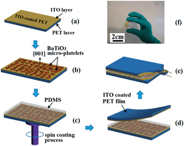
BaTiO3 platelets (30 mg) were dispersed in 40 ml of de-ionized water. Hexane (3 ml) was added to the vessel to form a hexane/water interface. After stirring, the BaTiO3 platelets immediately gathered at the interface. Most of the hexane at the top of the vessel was removed by syringe, and the densely packed film was transferred to an ITO coated flexible plastic substrate by dip-coating. After deposition, the film was dried at room temperature to obtain a monolayer film. The PDMS was spin-coated on the oriented BaTiO3 monolayer film and cured in an oven. An ITO coated PET film was attached to the surface of the BaTiO3–PDMS composite. A DC electric field of ∼3 kV mm−1 was applied for electric poling at room temperature.2.3 Characterization and application
The crystal structures of the BaTiO3 micro-platelets and oriented film were examined using X-ray diffraction (XRD) on a Panalytical X'pert Pro diffractometer using Cu-Kα radiation (λ = 1.5418 Å). The morphologies of the products were investigated using SEM (Philips XL30). The output voltage and current were measured using a Keithley 2400 source meter.The piezoelectric generator was demonstrated to harvest the energy output of wind. The generator was connected with a LCD to demonstrate the application of powering an electronic device.
3. Results and discussion
3.1 The self-assembly of oriented BaTiO3 films
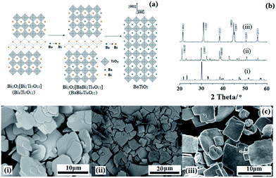
The conversion process of BaTiO3 micro-platelets is illustrated in Fig. 1.The first step is designed to form a precursor that has a layered-perovskite structure and can be easily transformed to BaTiO3. According to the literature, Aurivillius-structured compositions are reasonable candidates.43 Aurivillius family structures have the formula Bi2O2(An−1BnO3n+1) with a [Bi2O2] interlayer and a perovskite sub-lattice. One interesting feature of Aurivillius phases is the compositional flexibility of the perovskite blocks that allows the incorporation of various cations. The [Bi2O2] slabs can be removed after a high-temperature treatment process and A-site ions can be replaced by other elements through topochemical techniques and form a perovskite phase.
In this work, BaTiO3 particles with a plate-like morphology were synthesized from the Aurivillius phase BaBi4Ti4O15 by a topochemical conversion reaction. Bismuth oxide sub-layers were first removed at this temperature. Ba2+ ions were dissolved into the lattice and replaced the Bi3+ ions without destroying the particle morphology. Fig. 1b and c show the XRD patterns and SEM images of the Bi4Ti3O12 and BaBi4Ti4O15 precursors and BaTiO3 particles, respectively, and they also illuminate the topochemical evolving process. The XRD pattern of Fig. 1b (ii) shows that the particles are of a single phase with all of the diffraction peaks attributable to a layered structure, assigned to JCPDS no. 350757. The strong intensities of the (0010) and (0018) peaks indicate that the surface of the BaBi4Ti4O15 platelet was parallel to (00L). Fig. 1b (iii) shows the XRD pattern of BaTiO3 particles prepared from BaBi4Ti4O15 particles by a topochemical reaction at 950 °C for 4 h. It can be seen that the BaTiO3 particles exhibit a single-phase perovskite structure, assigned to JCPDS no. 05-0626. The much stronger intensity of the (001) and (002) planes of the BaTiO3 micro-platelets illustrated a strong 〈00L〉 orientation. The split of the (200) and (002) peaks indicated that the BaTiO3 plate-like particles have a tetragonal structure rather than cubic.
In Fig. 1c (ii) and Fig. 1c (iii), it can be seen that the BaTiO3 particles have an average size of 7 μm and show a regular plate shape. The regularly shaped BaBi4Ti4O15 particles acted as a “template” during the topochemical microcrystal conversion process. The ion exchanging process accompanied with bond breaking would unavoidably influence the integrity of the crystallinity, so control of the temperature became the key parameter in the topochemical microcrystal conversion process. An appropriate reaction temperature can not only remove the bismuth oxide [Bi2O2] sub-layers from the Aurivillius phase but can also dissolve the Ba2+ ions into the lattice to replace the Bi3+ ions while maintaining the preserved particle morphology.
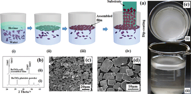
The plate-like morphology of the obtained BaTiO3 particles provides a good feature for assembling a film using an interfacial strategy. It is easier for plate-like particles to be held at the water/oil interface by interfacial tension. According to the process which is described in the experimental part, a BaTiO3 film was obtained, as shown in Fig. 2.
The assembling procedure of BaTiO3 film is illustrated in Fig. 2a, in the following order: (i) dispersion of the BaTiO3 platelets in hexane/water solution, (ii) self-assembly of BaTiO3 platelets at the hexane/water interface into a monolayer film, (iii) removal of the hexane phase using a syringe, (iv) transfer of the as-assembled film to an ITO coated PET substrate.
The surface of the ITO coated plastic substrate is covered with monolayer plate-shaped crystallites and the particles are in close contact with one another. The main force of the assembly of the particles should be the decrease of the interfacial energy. It can also be found that there is no obvious overlapping of the plate-shaped crystallites. The XRD pattern of the self-assembled film is given in Fig. 2b. The highly preferred orientation of the crystallites deposited on the substrate can be confirmed by XRD. In comparison with that of the BaTiO3 platelet powders, (seen in Fig. 2b (ii)), the (001) and (002) peaks of the assembled BaTiO3 film are sharper and the other peaks are absent, which should be attributed to preferential crystallite orientation in the film.
Typical scanning electron microscopy (SEM) images of the BaTiO3 film (Fig. 2c and d) confirm that BaTiO3 platelets were aligned in parallel to the substrate surface to form a densely packed film. These results clearly demonstrate that a highly oriented film consisting of BaTiO3 platelets was obtained using the interfacial self-assembly strategy. Fig. 2e shows physical photos of the assembly of the film at the oil/water interface, which visually indicated that the hexane/water interface effectively captured the BaTiO3 platelets to assemble a film.
3.2 Fabrication and performance of the assembled BaTiO3 film-based piezoelectric generator (PG)
Schematic diagrams of the piezoelectric generator fabrication process are shown in Fig. 3 and detailed information is described in the experimental section. The oriented monolayered BaTiO3 film generates a piezoelectric potential under external stress and acts as an energy generation source. Fig. 3f shows the completely bent piezoelectric generator device on an ITO-coated flexible substrate. These images confirm that the device is very flexible and bendable.3.3 Proposed power generation mechanism of the piezoelectric generator
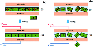
Now we briefly discuss the power generation mechanism. The spontaneous electric dipoles in BaTiO3, originating from Ti4+ ion movement in the TiO6 octahedra, can have six possible orientations along the 〈001〉 direction.As shown in Fig. 4a, the normal direction of the BaTiO3 platelet is parallel to the 〈001〉 crystallographic axes, which has been confirmed using XRD analysis. Therefore, when a high enough electric field is applied along the perpendicular direction of the oriented BaTiO3 film, the ferroelectric domain (black arrows) would tend to totally turn toward the electric field direction. However, if the BaTiO3 particles are randomly oriented inside the PDMS polymer, when a high electric field is applied, the ferroelectric domains tend to turn toward the direction along the electric field direction, but only have a limited turning angle, including 90° and 180°, so after high electric field poling, most domains may tilt from the electric field direction, as shown in Fig. 4b.
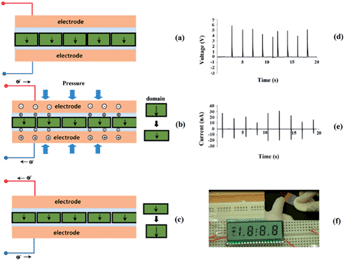
The generator device and power generation mechanism are illustrated in Fig. 5 in which the BaTiO3 film was working in a thickness expansion mode (d33) with a pressure applied on the top surface of the piezoelectric generator. The applied pressure was transferred to the BaTiO3 platelets through the PDMS matrix and resulted in charge generation. For the domain tilt from the normal stress direction, only the component along the normal stress direction provides the effective piezoelectric potential, so under the effect of the same strain, the 〈001〉 preferred oriented film will produce a higher piezoelectric potential and more charges will be accumulated at the top and bottom electrodes. This mechanism explains why the 〈001〉 preferred orientation film has the advantage for energy harvesting applications.
Once mechanical pressure is applied onto the nanogenerator as shown in Fig. 5a and b, the strain enhances the dipole component which generates positive and negative piezopotentials at the top and bottom electrodes and the piezopotentials induce the flow of the charge carrier in the external load. Subsequently, when the pressure is released, the dipole component will return to the initial state, the piezopotential will fade away and the charge carriers then flow back and produce the reverse output signals, as shown in Fig. 5b and c.
To prove the practical application of the NG, we connected the PG to a LCD display (Fig. 5f). The output voltage and current are displayed in Fig. 5d and e, respectively. It can be noticed that a LCD with an operation voltage of 3 V is directly connected to the developed NG without the aid of a capacitor. The NG was tapped by a ceramic block impact (seen in Fig. 5f (inset)), and it instantly turned the full screen LCD on as in Fig. 5f.
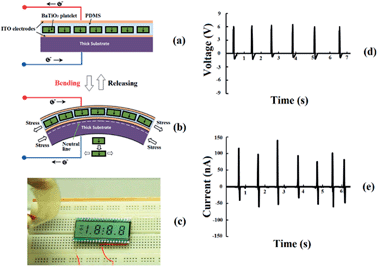
In Fig. 6, another working mode of the NG was also examined by bending the device. The NG was bent and released repeatedly, and consistent output voltage and current were generated (Fig. 6b and c).
In this bending mode, to optimize the output performance, the structure of the PG should be unsymmetrical, as shown in Fig. 6a. When we bend the piezoelectric device, a strain neutral line is located near the plastic substrate because the bottom plastic substrate layer is much thicker than the BaTiO3–PDMS polymer composite layer, so the active piezoelectric layer can be an integral part for the tensile strain or compressive strain, otherwise, there will be a self-offset effect in the active piezoelectric layer.
Therefore, when the PG is bent, the BaTiO3–PDMS polymer composite is subject to tensile strain, as shown in Fig. 6b. The deformation of the BaTiO3 platelets produces a piezoelectric potential in the piezoelectric generator, which drives the flow of external electrons and produces an electric power output. Fig. 6c and d show the open-circuit voltage and short-circuit current outputs. The maximum voltage and current outputs reached 6.5 V and 140 nA, respectively.
To verify the origin of the nanogenerator's output, switching tests44 were performed and the test results are shown in Fig. S1.† The opposite sequence of peak occurrence with time according to the forward or reverse connections proved that the output signals originate from the piezoelectricity of BaTiO3.
We measured the outputs of the PG device under periodic bending and unbending in the bending stage which is driven by a linear motor. The device was well packaged and fixed at the stage. The results are shown in Fig. S2.† The voltage amplitude does not appear to have changed significantly after 500 time cycles, which shows a good mechanical stability of the PG device.
3.4 The application of the piezoelectric generator for wind energy harvesting
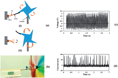
To evaluate the output performance, the application of this PG for the harvesting of wind energy has been demonstrated, as shown in Fig. 7. This PG device was fixed on a support and tapped by a paddle which was attached to one of the blades of a windmill rotating in the wind. The PG produced voltage and current outputs which reached up to 2.3 V and 96 nA, respectively, as shown in Fig. 7c and d. The output was sufficient enough to light a LCD (seen in Fig. 7b and in the ESI video S1†).To evaluate the output power of the PG for wind energy harvesting, an adjustable external load was connected to the PG. When the PG was tapped by the windmill and the wind was kept at the same level, the output power of the PG was calculated according to the following eqn (4):22
 | (4) |
The test results indicated that when the external load is 80 MΩ, the output power of the PG reached a maximum value of 0.021 μW. The results are shown in detail in Fig. S3.†
Fig. S3(a)† shows the average power of the PG device when varying the load resistance. Fig. S3(b) and (c)† show the instantaneous voltage and power at an 80 MΩ external load resistance, respectively. Thus, according to the dimension of the device (length 2.0 cm, width 1.0 cm), the surface power density was 10.5 nW cm−2. The power density of the PG is not higher than those in previous reports, which should be attributed to the lower content of the piezoelectric active materials in the PG device. Theoretically, the interfacial assembling method should increase the dispersion density of the piezoelectric particles in the BaTiO3–PDMS composite layer, however, the self-assembled monolayer BaTiO3 film is only about 1 μm in thickness, therefore, this situation determined that the volume ratio of the piezoelectric active materials in the device is not as much as those in some previous reports, which results in an output power that is not as high. In fact, we have tested the volume power density of the piezoelectric active materials (BaTiO3 film). The total active volume of the BaTiO3 film was about 2.0 × 104 cm3 (length 2.0 cm, width 1.0 cm, thickness 1 μm). The cross sectional SEM images of the self-assembled BaTiO3 film-based PG device are shown in Fig. S4.† Thus, the volume power density was about 105 μW cm−3. Although the value is lower than that in other reports,20 in view of the difference in the piezoelectric constants, the results are reasonable. Up to now, the output of the self-assembled monolayer BaTiO3 film-based PG is not excellent enough compared to those in some previous reports,23,30 but the strategy of improving the piezoelectric properties by controlling the preferred orientation is significant for enhancing the performance of piezoelectric energy harvesting devices. In further work, we will try to stack up the monolayer BaTiO3 film into multilayer films, by improving the assembling technique, to enhance the output performance of the PG device.
Now, we summarize the merits of this kind of piezoelectric generator based on an oriented BaTiO3 film. Firstly, the large piezoelectric coefficient inherited from the perovskite ferroelectric material is quite useful for energy harvesting applications and the BaTiO3 is lead-free and environmentally friendly. Secondly, the interfacial assembly method of the particles provides a facile and low cost technique to obtain a large scaled intensively assembled film. This method also overcomes the problem that the particles are difficult to disperse in the PDMS matrix by conventional mixing techniques, so even with a high volume fraction of the BaTiO3 particles inside the composite, the flexibility of it will not be destroyed. Thirdly, the piezoelectric generator-based on an oriented film prepared by interfacial assembly adequately exploits the anisotropic characteristics of perovskite piezoelectric materials.
4. Conclusions
In summary, we fabricated a self-assembled 〈001〉 oriented BaTiO3 film-based flexible piezoelectric generator. BaTiO3 micro-platelets with a special 〈001〉 orientation have been synthesized by topochemical microcrystal conversion and we have used a facile interfacial self-assembly method to form a highly 〈001〉 oriented monolayer film. On the basis of the highly 〈001〉 oriented monolayer BaTiO3 film, a novel flexible piezoelectric generator was prepared. It was demonstrated that the piezoelectric generator converts mechanical deformation into electric energy. We discussed the principle of power generation and the advantage of a self-assembled BaTiO3 film-based piezoelectric generator. The PG was employed to harvest wind energy with the aid of a windmill and the power output was sufficient enough to light a full screen LCD.Acknowledgements
This research work was supported by the National Natural Science Fund of China (no. 51202204), and the Fundamental Research Funds for the Central Universities of China (no. 2010121052).Notes and references
- Z. L. Wang and J. Song, Science, 2006, 312, 242–246 CrossRef CAS PubMed.
- S. N. Cha, J.-S. Seo, S. M. Kim, H. J. Kim, Y. J. Park, S.-W. Kim and J. M. Kim, Adv. Mater., 2010, 22, 4726–4730 CrossRef CAS PubMed.
- B. Kumar and S.-W. Kim, Nano Energy, 2012, 1, 342–355 CrossRef CAS PubMed.
- X. D. Wang, J. H. Song, J. Liu and Z. L. Wang, Science, 2007, 316, 102–105 CrossRef CAS PubMed.
- X. Wang, J. Song and Z. L. Wang, J. Mater. Chem., 2007, 17, 711–720 RSC.
- B. Kumar and S.-W. Kim, J. Mater. Chem., 2011, 21, 18946–18958 RSC.
- K.-I. Park, M. Lee, Y. Liu, S. Moon, G.-T. Hwang, G. Zhu, J. E. Kim, S. O. Kim, D. K. Kim, Z. L. Wang and K. J. Lee, Adv. Mater., 2012, 24, 2999–3004 CrossRef CAS PubMed.
- M. Zhang, T. Gao, J. Wang, J. Liao, Y. Qiu, H. Xue, Z. Shi, Z. Xiong and L. Chen, Nano Energy, 2015, 11, 510–517 CrossRef CAS PubMed.
- K.-I. Park, S. Xu, Y. Liu, G.-T. Hwang, S.-J. L. Kang, Z. L. Wang and K. J. Lee, Nano Lett., 2010, 10, 4939–4943 CrossRef CAS PubMed.
- S.-H. Shin, Y.-H. Kim, M. H. Lee, J.-Y. Jung and J. Nah, ACS Nano, 2014, 8, 2766–2773 CrossRef CAS PubMed.
- J. M. Wu, C. Xu, Y. Zhang and Z. L. Wang, ACS Nano, 2012, 6, 4335–4340 CrossRef CAS PubMed.
- J. M. Wu, C. Xu, Y. Zhang, Y. Yang, Y. Zhou and Z. L. Wang, Adv. Mater., 2012, 24, 6094–6099 CrossRef CAS PubMed.
- K. Y. Lee, D. Kim, J.-H. Lee, T. Y. Kim, M. K. Gupta and S.-W. Kim, Adv. Funct. Mater., 2014, 24, 37–43 CrossRef CAS.
- J. H. Jung, M. Lee, J.-I. Hong, Y. Ding, C.-Y. Chen, L.-J. Chou and Z. L. Wang, ACS Nano, 2011, 5, 10041–10046 CrossRef CAS PubMed.
- C. K. Jeong, K.-I. Park, J. Ryu, G.-T. Hwang and K. J. Lee, Adv. Funct. Mater., 2014, 24, 2620–2629 CrossRef CAS.
- H. B. Kang, J. Chang, K. Koh, L. Lin and Y. S. Cho, ACS Appl. Mater. Interfaces, 2014, 6, 10576–10582 CAS.
- K. N. Kim, J. Chun, S. A. Chae, C. W. Ahn, I. W. Kim, S.-W. Kim, Z. L. Wang and J. M. Baik, Nano Energy DOI:10.1016/j.nanoen.2015.01.004.
- S. Y. Xu, Y. W. Yeh, G. Poirier, M. C. McAlpine, R. A. Register and N. Yao, Nano Lett., 2013, 13, 2393–2398 CrossRef CAS PubMed.
- S. Xu, G. Poirier and N. Yao, Nano Energy, 2012, 1, 602–607 CrossRef CAS PubMed.
- W. W. Wu, L. Cheng, S. Bai, W. Dou, Q. Xu, Z. Y. Wei and Y. Qin, J. Mater. Chem. A, 2013, 1, 7332–7338 CAS.
- M. Yuan, L. Cheng, Q. Xu, W. Wu, S. Bai, L. Gu, Z. Wang, J. Lu, H. Li, Y. Qin, T. Jing and Z. L. Wang, Adv. Mater., 2014, 26, 7432–7437 CrossRef CAS PubMed.
- X. Chen, S. Y. Xu, N. Yao and Y. Shi, Nano Lett., 2010, 10, 2133–2137 CrossRef CAS PubMed.
- L. Gu, N. Cui, L. Cheng, Q. Xu, S. Bai, M. Yuan, W. Wu, J. Liu, Y. Zhao, F. Ma, Y. Qin and Z. L. Wang, Nano Lett., 2012, 13, 91–94 CrossRef PubMed.
- C.-Y. Chen, T.-H. Liu, Y. Zhou, Y. Zhang, Y.-L. Chueh, Y.-H. Chu, J.-H. He and Z. L. Wang, Nano Energy, 2012, 1, 424–428 CrossRef CAS PubMed.
- S. Bai, Q. Xu, L. Gu, F. Ma, Y. Qin and Z. L. Wang, Nano Energy, 2012, 1, 789–795 CrossRef CAS PubMed.
- K.-I. Park, C. K. Jeong, J. Ryu, G.-T. Hwang and K. J. Lee, Adv. Energy Mater., 2013, 3, 1539–1544 CrossRef CAS.
- K.-I. Park, S. B. Bae, S. H. Yang, H. I. Lee, K. Lee and S. J. Lee, Nanoscale, 2014, 6, 8962–8968 RSC.
- M. J. Polking, M.-G. Han, A. Yourdkhani, V. Petkov, C. F. Kisielowski, V. V. Volkov, Y. Zhu, G. Caruntu, A. Paul Alivisatos and R. Ramesh, Nat. Mater., 2012, 11, 700–709 CrossRef CAS PubMed.
- F. Jona and G. Shirane, Ferroelectric crystals, Dover, New York, 1993 Search PubMed.
- Y. Zhao, Q. Liao, G. Zhang, Z. Zhang, Q. Liang, X. Liao and Y. Zhang, Nano Energy, 2015, 11, 719–727 CrossRef CAS PubMed.
- Y. Lin, H. Skaff, T. Emrick, A. D. Dinsmore and T. P. Russell, Science, 2003, 299, 226–229 CrossRef CAS PubMed.
- H. Duan, D. Wang, D. G. Kurth and H. Möhwald, Angew. Chem., Int. Ed., 2004, 43, 5639–5642 CrossRef CAS PubMed.
- J. Matsui, K. Yamamoto, N. Inokuma, H. Orikasa, T. Kyotani and T. Miyashita, J. Mater. Chem., 2007, 17, 3806–3811 RSC.
- L. F. Hu, R. Z. Ma, T. C. Ozawa, F. X. Geng, N. Iyi and T. Sasaki, Chem. Commun., 2008, 4897–4899 RSC.
- L. Hu, L. Wu, M. Liao and X. Fang, Adv. Mater., 2011, 23, 1988–1992 CrossRef CAS PubMed.
- L. F. Hu, R. Z. Ma, T. C. Ozawa and T. Sasaki, Angew. Chem., Int. Ed., 2009, 48, 3846–3849 CrossRef CAS PubMed.
- F. Reincke, W. K. Kegel, H. Zhang, M. Nolte, D. Wang, D. Vanmaekelbergh and H. Mohwald, Phys. Chem. Chem. Phys., 2006, 8, 3828–3835 RSC.
- D. Liu, Y. K. Yan and H. P. Zhou, J. Am. Ceram. Soc., 2007, 90, 1323–1326 CrossRef CAS PubMed.
- W. Zhao, H. Zhou, Y. Yan and D. Liu, J. Am. Ceram. Soc., 2008, 91, 1322–1325 CrossRef CAS PubMed.
- Y. Chang, H. Ning, J. Wu, S. Zhang, T. Lü, B. Yang and W. Cao, Inorg. Chem., 2014, 53, 11060–11067 CrossRef CAS PubMed.
- Y.-f. Liu, Y.-n. Lu, M. Xu, L.-f. Zhou and S.-z. Shi, Mater. Chem. Phys., 2009, 114, 37–42 CrossRef CAS PubMed.
- S. F. Poterala, J. R. J. Meyer and G. L. Messing, J. Am. Ceram. Soc., 2011, 94, 2323–2329 CrossRef CAS PubMed.
- S. F. Poterala, Y. F. Chang, T. Clark, R. J. Meyer and G. L. Messing, Chem. Mater., 2010, 22, 2061–2068 CrossRef CAS.
- R. Yang, Y. Qin, C. Li, L. Dai and Z. L. Wang, Appl. Phys. Lett., 2009, 94, 022905 CrossRef PubMed.
Footnote |
| † Electronic supplementary information (ESI) available. See DOI: 10.1039/c5ta01079a |
| This journal is © The Royal Society of Chemistry 2015 |

