 Open Access Article
Creative Commons Attribution 3.0 Unported Licence
Recent developments in electrode materials for sodium-ion batteries
Luyuan Paul
Wang
ab,
Linghui
Yu
a,
Xin
Wang
c,
Madhavi
Srinivasan
*ab and
Zhichuan J.
Xu
*abd
aSchool of Materials Science and Engineering, Nanyang Technological University, 50 Nanyang Avenue, Singapore 639798, Singapore. E-mail: madhavi@ntu.edu.sg; xuzc@ntu.edu.sg
bEnergy Research Institute@NTU, ERI@N, Interdisciplinary Graduate School, Nanyang Technological University, 50 Nanyang Avenue, Singapore 639798, Singapore
cSchool of Chemical and Biomedical Engineering, Nanyang Technological University, 50 Nanyang Avenue, Singapore 639798, Singapore
dSolar Fuels Lab, Nanyang Technological University, 50 Nanyang Avenue, Singapore 639798, Singapore
First published on 3rd March 2015
Abstract
The rapid consumption of non-renewable resources has resulted in an ever-increasing problem of CO2 emissions that has motivated people for investigating the harvesting of energy from renewable alternatives (e.g. solar and wind). Efficient electrochemical energy storage devices play a crucial role in storing harvested energies in our daily lives. For example, rechargeable batteries can store energy generated by solar cells during the daytime and release it during night-time. In particular, lithium-ion batteries (LIBs) have received considerable attention ever since their early commercialization in 1990s. However, with initiatives by several governments to build large-scale energy grids to store energy for cities, problems such as the high cost and limited availability of lithium starts to become major issues. Sodium, which also belongs to Group 1 of the periodic table, has comparable electrochemical properties to Lithium, and more importantly it is considerably more accessible than lithium. Nonetheless, research into sodium-ion batteries (NIBs) is currently still in its infancy compared to LIBs, although great leaps and bounds have been made recently in terms of research and development into this technology. Here in this review, we summarize the recent advancements made, also covering the prospective materials for both the battery cathode and anode. Additionally, opinions on possible solutions through correlating trends in recent papers will be suggested.
1. Introduction
Lithium-ion batteries (LIBs) have emerged as one of the most popular choice for energy storage in portable devices, since their early commercialization in the 1990s. The success of LIBs has been mainly attributed to their high energy density, long cycle life and affordable cost. Furthermore, the small ionic radius of lithium ions helps facilitate rapid diffusion within crystal structures.1–12 However, as the popularity of lithium-based systems has continued to grow over the years, the demand for the raw materials has gradually outpaced the ability for its supply to recover.13,14 Controversial issues regarding the availability of battery grade raw materials have been debated. Most of the untapped lithium reserves have been found to be lying in isolated or geopolitically sensitive areas, in which the scaling up process would take large capital, involve a long lead time for processing of the raw material and which ultimately would lead to much higher expenses and a more costly product.15 The lack of lithium availability has resulted in the price of its raw materials rising massively over the past few years (Fig. 1).16 Thus, there exists an immediate need to come up with alternatives to lithium, especially in view of government policies to develop large-scale energy storage grids and devices.17–20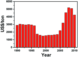 | ||
| Fig. 1 Average price of lithium precursor (Li2CO3) over the years. The sharp increase in price from 2004 was caused by the increasing demand for LIBs, while the decline in 2008 was due to the financial crisis affecting the demand for LIBs. The data is collected from ref. 16. | ||
Sodium, on the other hand, ranks as the world's 4th most widely abundant element on earth. Investigations into sodium-ion batteries (NIBs) began alongside LIBs in the 1970s, but were almost completely overshadowed by LIBs following the successful commercialization of LIBs by Sony in 1990.21,22 Despite the higher reducing potential that sodium (E = −2.7 V vs. S.H.E.) has over lithium (E = −3.04 V vs. S.H.E.), the cost per kW h of energy that sodium is able to provide can offer a tremendous advantage when a huge amount of alkali metal is required for large-scale applications. A brief comparison between lithium and sodium can be seen in Table 1.14,15 The operating principles of the NIBs are identical to that of the “rocking-chair” mechanism in LIBs.
| Sodium | Lithium | |
|---|---|---|
| Potential (V vs. S.H.E.) | −2.70 | −3.04 |
| Cation radii (Å) | 0.97 | 0.68 |
| Price (US$ per ton) | 250–300 | 5800 |
| Atomic weight (g) | 23 | 6.9 |
| Capacity (mA h g−1) | 1160 | 3860 |
In the operation, a separator crucially separates the cathode and anode and the set-up is submerged in a Na-ion containing electrolyte. During the charge and discharge processes, alkali ions shuttle between the two electrodes. Although it has been frequently pointed out that NIBs will always fall behind their lithium counterparts in terms of theoretical energy density due to the heavier weight of sodium, recent computational studies by Cedar's group have demonstrated by using computational simulation that the output voltage of certain sodium-based materials could vie with that of their lithium counterparts.23 Hence, there lies a huge opportunity for the investigation of novel and cheaper sodium-based compounds as energy storage materials amidst all the lithium hype.
Important parameters, including specific capacity, operating voltage and cycling performance of the battery, are largely determined by the electrochemical properties of the alkali ion accommodating structure. Several lithium-based compounds that have shown excellent intercalation chemistry as LIB electrodes, have also proven to exhibit comparatively good electrochemical performance in their sodium analogues (e.g. Na3V2(PO4)3, Na2FePO4F).24–30 For advances in the field of NIBs to occur, fundamental questions have to be first answered. These include questions about the mechanics in the diffusion of sodium ions through the SEI layer and into crystal structure, as well as the interaction of the electrolyte with the active particles. The kinetics and transport behaviours also need to be investigated to explain how sodium and lithium could be so similar but yet so electrochemically different.
In recent years, there has been a surge in the number of excellent reviews on room temperature NIBs.14,15,19,31–39 For instance, Ellis19 and Palomares35 compared the different types of sodium systems (e.g. aqueous/non-aqueous NIB, Na–S cell, Na-air cell and etc.) available. Kim,13 Pan39 and Yabuuchi37 covered in detail the different electrode materials that have been reported. Ponrouch et al. provided a detailed analysis on the various non-aqueous NIB electrolytes.36 Several other reviews focusing on either the anode34,38 or cathode32,33,40 have also been reported. However, we believe that the NIB family is constantly growing and frequent reviews are indeed necessary to assist progress towards commercialization of the technology. We aim to cover the advancements in electrode materials for NIBs that have been recently reported. For the cathodic component, we will focus on sodium intercalation alkali compounds. Here, a wide group of materials, including layered oxides, polyanionic phosphates, pyrophosphates, will be extensively reviewed. As for the negative electrodes, since the successful utilization of graphitic carbon in LIB could not be mimicked in NIBs, alternative materials, including hard carbons, alloying and conversion materials, will be covered in detail. Recently, organic compounds have also made a significant impact as alternative environmentally sustainable electrode materials and so will also be covered here. Finally, we will conclude with some perspectives on possible solutions and suggestions that could be of significant interest for progress in this field.
2. Positive electrode materials
Cathode materials in Na-ion batteries are able to reversibly insert Na ions within the crystal structure at a high redox potential, usually >2 V vs. Na+/Na. Ideal candidates for cathode materials should exhibit low volume expansion upon intercalating/deintercalating of the Na ion, in order to provide superior cycling performance for the cell. Research on Na intercalating compounds is not new and has already been thoroughly researched alongside LIB research over several decades.2.1. Oxides
A widely studied structure for the cathode material for LIBs would be layered oxides with the empirical formula LiMO2 (where M = one or more 3d ions with multiple oxidation states), because of their high intercalating potentials (vs. Li+/Li) and, hence, high energy density. The layered structure is made up of layers of edge-shared transition metal centered oxygen octahedra (MO6), in which the alkali ions are able to intercalate into either the trigonal prismatic (P) or octahedral (O) vacancy spot. Similar to their lithium analogues, such layered oxides also have the ability to accommodate Na ions too. Layered oxides are classified according to the stacking arrangement of the alkali ions between each interlayer.41,42 The different polytypes are each unique in terms of how the oxygen layers are being stacked. The general consensus follows where O and P refer to the octahedral and trigonal coordination of the alkali ion by oxygen within the interstitial layer of the crystal structure, respectively, while the number 2 or 3 represents the repeated transition metal layers within a unit cell; for example, ABCABC in O3, ABBA in P2 and ABBCCA in P3 as shown in Fig. 2. The difference in stacking order in each structure results in distinctive insertion sites for the alkali ions. However, unlike Li ions, Na ions are only able to occupy the trigonal prismatic sites in the P2 structure, due to the larger ionic size of the Na ion.43 Phase transition occurs during sodiation/desodiation in both O and P AMO2 phases, whereby gliding of the oxygen layers results in structural distortion and rearrangement. The phase structure is dependent on the number of Na ions that are intercalated in the structure.44,45 | ||
| Fig. 2 Crystal structure of various layered metal oxides. (a) P2-NaxMO2, (b) O3-NaxMO2, (c) P3-NaxMO2 (ref. 13). Copyright 2012 Wiley-VCH Verlag GmbH & Co. KGaA, Weinheim. | ||
LiCoO2 is one example from the AMO2 family that has seen tremendous success as a cathodic material in LIBs following its commercialization by Sony in 1990.46,47 Hence, it is not surprising that its Na counterpart, NaxCoO2, has attracted much interest as an alternative. In 1981, Delmas et al. compared the electrochemical properties of P2 and O3 NaxCoO2. During the electrochemical desodiation, it was observed that the O3 NaxCoO2 transformed into monoclinic distorted O′3 NaxCoO2 and finally to P3 NaxCoO2 within a Na content of 0.5 ≤ x ≤ 1.48 On the other hand, the P2 NaxCoO2 was found to be able to maintain its structure throughout electrochemical sodiation and desodiation. It was reported that for phase transition to take place from P2- to O-type structured NaxCoO2, energy is required for rotation of the CoO6 octaherdra and for cleavage of the Co–O bond. Hence, P2 NaxCoO2 generally retains its structure at room temperature during electrochemical cycling reactions.49
Shibata et al. reported the diffusion coefficient of Na ions into NaxCoO2 at 303 K with values of (0.7–1.9) × 10−11 cm2 s−1 (0.54 < x < 0.85), which are comparable to that of the diffusion coefficient (10−12 to 10−11) of Li in LiCoO2.50,51 Analogues of P2-NaxCoO2 were also investigated. The electrochemical discharge profiles of P2-NaxCoO2vs. P2-Na2/3Co2/3Mn1/3O2 are compared in Fig. 3a. P2-NaxCoO2 recorded a total of 9 phase transformations when cycled between 0.5 ≤ x ≤ 0.9. In contrast, Mn-doped P2-Na2/3Co2/3Mn1/3O2 exhibited a typical solid-solution like curve, with a single phase transformation at x = 0.67. 23Na MAS (Magic Angle Spinning) NMR (Nuclear Magnetic Resonance) was also carried out, with the results indicating the disordered arrangement of both Co3+ and Mn4+, which prevents structural transformation. However, a subsequent in situ X-ray Absorption Spectroscopy (XAS) carried out during the discharge process showed both Co and Mn K-edges shifted to a lower energy level when the Na content > 0.67 (Fig. 3b), indicating a concurrent reduction in both Co3+/Co2+ and Mn4+/Mn3+during the structural change.52,53
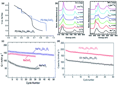 | ||
| Fig. 3 (a) 2nd discharge curve comparison of P2-NaxCoO2 and P2-NaxCo2/3Mn1/3O2 (ref. 53) (b) normalized in situ X-ray Absorption Spectroscopy (XAS) of P2-NaxCo2/3Mn1/3O2 with respect to the reference materials, revealing shifts in the peaks during the discharge process, indicating the simultaneous redox reaction occurring in Co3+/Co2+ and Mn4+/Mn3+ (ref. 52) (c) comparison of cycling capability between different oxides.54 (d) Comparison of cycling discharge capacity between P2 and O3-Nax[Fe1/2Mn1/2]O2 (ref. 55) (a) reproduced from ref. 53 with permission from The Royal Society of Chemistry (b) reprinted with permission from ref. 52. Copyright 2014 American Chemical Society (c) reprinted with permission from ref. 54. Copyright 2013 Elsevier (d) reprinted with permission from Macmillan Publishers Ltd.: (Nat. Mater.) (ref. 55), Copyright 2012. | ||
O3-NaFeO2 similarly belongs to the group of layered oxides that has potential electrochemical storage capabilities. Yabuuchi et al. synthesized NaFeO2via a simple solid-state method and with varying different cut-off voltages to evaluate its cycling performance. The optimum performance was observed when the cut-off voltage was limited to 3.5 V. Despite the low initial specific capacity of 80 mA h g−1, its cycling performance demonstrated a reversible retention of 75% after 30 cycles. Ex situ XRD revealed the presence of an irreversible structure change when the cut-off voltage was increased to 4.0 V and over vs. Na+/Na (x ≥ 0.4 in Na1−xFeO2), which explained the severe capacity fading.56 Moving on, the partial substitution of Fe with Co in NaFeO2 has been effectively shown to suppress the iron migration that was previously observed in the first principle calculations.57 The cycling performance of O3-type NaFe1/2Co1/2O2 compared to NaFeO2 and NaCoO2, is shown in Fig. 3c. NaFe1/2Co1/2O2 was able to deliver a reversible capacity of 160 mA h g−1 (C/20) within 1.5–4.0 V vs. Na+/Na with an energy density of 510 W h kg−1.54
Komaba's group also recently compared the electrochemical performance of P2-and O3-type Nax[Fe1/2Mn1/2]O2 in a sodium cell set-up. The rationale for the synthesis of Nax[Fe1/2Mn1/2]O2 stems from the fact that the Fe4+ cation in P2-NaxFeO2 cannot be stabilized in its oxide structure under ambient conditions, along with the partial reversibility problem in NaFeO2, as previously mentioned. The P2-type Na2/3[Fe1/2Mn1/2]O2 was able to deliver a reversible capacity of up to 190 mA h g−1, compared to 124 mA h g−1 in O3-Na[Fe1/2Mn1/2]O2, as shown in Fig. 3d. The capacity delivered by P2-Na2/3[Fe1/2Mn1/2]O2 is approximately 72% of its theoretical capacity, assuming a single electron transfer of a M3+/M4+ (M = Fe1/2, Mn1/2) couple. In addition, the energy density is estimated to be about 520 W h kg−1, which is comparable to 530 W h kg−1 demonstrated in LiFePO4. However, the electrode stability of the P2-type Na2/3[Fe1/2Mn1/2]O2 is rather poor, as shown by a capacity retention of approximately 77% at the end of 30 cycles. Na2/3Ni1/3Mn1/2Ti1/6O2 was able to deliver a reversible capacity of 127 mA h g−1 at an average voltage plateau of 3.7 V vs. Na+/Na. The energy density is estimated to be 470 W h kg−1 in a half-cell configuration. Furthermore, it was found that the presence of Ti helps to suppress the volume change during charge discharge, hence leading to excellent cyclability performance compared to P2-type Na2/3[Fe1/2Mn1/2]O2.58
Another prospective cathode material for NIB is the monoclinic O′3 NaNiO2. The electrochemical profile of NaNiO2 is similar to that of P2-NaxCoO2, with multiple well-defined phase transformations during charge/discharge processes. In situ XRD during the discharge process revealed several phase transformations of O′3, P′3, P′′3, O′′3 and O′′′3 layered structures when cycled in a voltage range of 1.5–4.0 V at a rate of C/10. The NaNiO2 recorded a 1st charge capacity of 160 mA h g−1; however, only 114.6 mA h g−1 is obtained during the 1st discharge process.59 Cedar et al. described, through XRD and galvanostatic discharge results, how the excess capacity was attributed to the removal of the higher Na content of ∼0.91 in the 1st cycle, compared to a much lower Na content ∼0.52 during subsequent cycles.60 Hasa et al. also demonstrated the synthesis of P2 layered Na0.5[Ni0.23Fe0.13Mn0.63]O2via a simple co-precipitation/rinsing method. Fig. 4a shows the electrochemical response within a voltage window of 1.5–4.6 V (vs. Na+/Na) at increasing current densities (C/10 to 5C). At a rate of C/10, the capacity achieved was 180 mA h g−1, which decreased with an increasing rate to 60 mA h g−1 at 5C. Moreover, a near complete capacity was observed when the current reverted back to C/10, which indicated rapid kinetics during sodiation/desodiation, as well as exceptional electrode stability.61 Kim et al. fabricated layered Na[Ni1/3Fe1/3Mn1/3]O2via a solid-state synthesis and tested this in both half (vs. sodium metal) and full (vs. hard carbon) cell configuration. The half-cell exhibited gradual sloping electrochemical profiles with a reversible capacity of 100 mA h g−1 (0.5C) for up to 150 cycles when tested between 1.5 and 4.0 V. Furthermore, ex situ XRD showed excellent crystal structure integrity even after 123 cycles. The 1st cycle charge discharge curve of the NayC/Na1−y[Ni1/3Fe1/3Mn1/3]O2 full cell showed an initial irreversible capacity of approximately 28%, which could be attributed to the formation of SEI. The cycling performance of the full cell (Fig. 4b) demonstrated a capacity retention of approximately 70% after 150 cycles, while the coulombic efficiency increased and was stable at 99% after the initial SEI formation cycles.62 A quaternary layered oxide (O3-Na(Mn0.25Fe0.25Co0.25Ni0.25)O2) was also reported recently by Cedar's group. X-ray Absorption Near Edge Structure (XANES) was carried out and the valence states of Mn, Fe, Co, Ni in the quaternary structure were determined to be 4+, 3+, 2+ and 1+, respectively. Additionally, in situ XRD was carried out to determine the structure evolution of the quaternary structure, revealing a transition of O3–P3–O3′–O3′′ during Na deinsertion. Comparably to other O3 group materials, the quaternary oxide was able to deliver a much higher capacity of 180 mA h g−1 when cycled between 1.9 and 4.3 V, producing an energy density of 578 W h kg−1. The electrochemical performance of the quaternary oxide was compared to O3-Na(Fe0.5Co0.5)O2 and O3-Na(Ni0.5Mn0.5)O2, as shown in Fig. 5a. The synergistic effect of the multiple transition metals in O3-Na(Mn0.25Fe0.25Co0.25Ni0.25)O2 allows it to be much more stable at higher cut-off voltages during cycling (Fig. 5b), in which high cut-off voltage is an issue present in Na(Fe0.5Co0.5)O2, as well as in Na(Ni0.5Mn0.5)O2.63 Similarly, copper-based layered electrode materials (P2-Na0.68Cu0.34Mn0.66O2, P2-Na0.68Cu0.34Mn0.55Ti0.16O2, O′3-NaCu0.67Sb0.33O2 and O3-Na0.9Cu1/4 Fe1/4Mn1/4Ti1/4O2) were studied as prospective cathode materials in NIBs.64,65 The materials demonstrated the use of Cu2+/Cu3+ redox pairs for energy storage. Whilst their specific capacity was lower compared to NaCuO2,66 the average voltage plateaus and cyclability of the doped compounds were significantly enhanced.
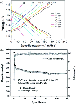 | ||
| Fig. 4 (a) Rate capability of Na0.5[Ni0.23Fe0.13Mn0.63]O2 at different cycles.61 (b) Cycling capability and coulombic efficiency of NayC/Na1−y(Ni1/3Fe1/3Mn1/3)O2 cell.62 (a) Copyright 2014 Wiley-VCH Verlag GmbH & Co. KGaA, Weinheim (b) reprinted with permission from ref. 62. Copyright 2012 Elsevier. | ||
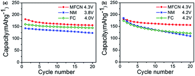 | ||
| Fig. 5 Cycling capability of quaternary oxide O3-Na(Mn0.25Fe0.25 Co0.25Ni0.25)O2 at (a) different cut-off voltage (b) similar cut-off voltage63 reprinted with permission from ref. 63. Copyright 2014 Elsevier. | ||
Other oxides, including NaCrO2,67,68 have been of recent particular interest in light of the fact that the lithium counterpart, LiCrO2, demonstrates a poor reversible capacity of only 10 mA h g−1, while a reversible capacity of 120 mA h g−1 can be achieved in NaCrO2 (Fig. 6).69 The authors believed that the bonding distance affects the reactivity of the two different compounds. In the case of LiCrO2, Cr4+ in the tetrahedral sites tends to disproportionately convert into Cr6+ during charging, which easily gets trapped within the tetrahedral sites. However, this does not occur in NaCrO2, as XANES elucidated that Cr4+ is the more stable redox state during charging.70 The larger size of the Cr4+ (compared to Cr6+) restricts the irreversible migration, ensuring Cr4+ stays within the interslab layers, thus allowing for reversible sodiation/desodiation. This example opens up several opportunities to look into the sodium counterpart of lithium-based materials that have previously been considered electrochemically inactive in LIBs.
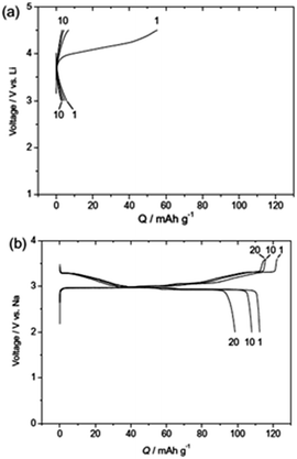 | ||
| Fig. 6 Comparison of charge–discharge profiles for (a) LiCrO2 and (b) NaCrO2 tested at a current density of 20 mA g−1 (ref. 67) reprinted with permission from ref. 67. Copyright 2010 Elsevier. | ||
Manganese-based oxides are known to crystallize in different polymorphs depending on the synthesis method. Several polymorphs exist because of the different ways MnO6 octahedra are interlinked. Hollandite α-MnO2, which has corner and edge sharing octaherdra forming large 2 × 2 tunnels for facile ion diffusion along the c-axis, have been considered as potential alkali-ion battery material. Additionally, the computational results have exhibited interesting results, indicating that the migration barriers for the diffusion of both Li and Na ions within the structure are comparable.71 Su et al. synthesized α-MnO2 and β-MnO2 nanorods via a facile hydrothermal synthesis, and recorded initial discharge capacities of 278 and 298 mA h g−1, respectively (Fig. 7a), which subsequently dropped to 204 and 250 mA h g−1 in the second cycle, respectively.72 However, they did not explain why the initial capacity was recorded to be much higher than the theoretical capacity of 244 mA h g−1 assuming single electron transfer. Tarascon et al. demonstrated Na insertion into λ-MnO2, in which the spinel-based structure irreversibly transformed into a layered structure after the 1st discharge cycle (Fig. 7b). Following the irreversible phase transformation, only 0.6 mol of Na ions could be reversibly extracted out.73
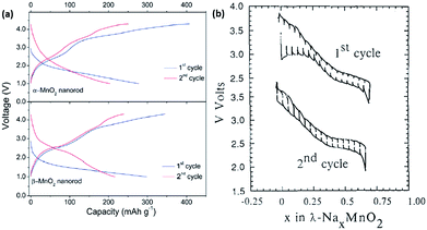 | ||
| Fig. 7 (a) Galvanostatic charge–discharge curves during the 1st and 2nd cycle of α-MnO2 and β-MnO2 tested at a current density of 20 mA g−1, respectively72 (b) galvanostatic charge–discharge curve of λ-MnO2 cycled between the voltage window of 2.0–4.0 V. Top curve shows the 1st cycle, while the bottom curve shows the 2nd cycle.73 (a) Reproduced from ref. 72 with permission from The Royal Society of Chemistry (b) reprinted with permission from ref. 73. Copyright 1992 Elsevier. | ||
Pre-sodiated manganese oxide, Na0.44MnO2 (also known as Na4Mn9O18), has also been thoroughly investigated over the years, particularly because of its attractive large-sized tunnels for sodium insertion.74–76 Sauvage et al. studied pure Na0.44MnO2 samples synthesized via a solid-state method and recorded a specific capacity of ∼80 mA h g−1 when cycled at a rate of C/10 over a voltage range between 2.0 and 3.8 V vs. Na+/Na. A potentiostatic intermittent titration technic (PITT) was also carried out at an extremely slow rate of C/200, as shown in Fig. 8a. The peak shifts during sodiation indicated an expansion of the lattice parameters with respect to the accommodation of the sodium ions. No new phases were detected, as could be backed up by the biphasic transition in the electrochemical profiles, indicating similar crystal structures of the sodiated and desodiated phases.74 However, an ab initio study coupled with experiments found that seven intermediate phases were present during the electrochemical charge/discharge. The results are shown in Fig. 8b, and reveal that the calculated voltage profile along the minimum energy path of formation is in coherence with that of the first experimental galvanostatic cycle.75 It is well documented that the nanosizing of materials could lead to improved properties, including a higher electrode–electrolyte interface for improved ion diffusion.2 Cao et al. synthesized uniform Na0.44MnO2 nanowires (diameter ≈ 50 nm) through a polymer–pyrolysis method. The galvanostatic charge–discharge curves exhibited a capacity of 130 mA h g−1 at a rate of 0.1C. A full cell coupled with a hard carbon anode demonstrated an initial capacity of about 109 mA h g−1 over a voltage window of 2.5 V. However, capacity fading was severe, with only 73% capacity retained after 100 cycles.76
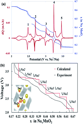 | ||
| Fig. 8 (a) PITT (blue dotted line) curve, starting with the reduction reaction (at C/200 with a 5 mV step) of the Na0.44MnO2/C composite.74 (b) Calculated voltage profile of Na0.44MnO2 along the minimum energy path of the formation energies, which agrees well with that of the experimental values.75 (a) Reprinted with permission from ref. 74. Copyright 2007 American Chemical Society (b) reprinted with permission from ref. 75. Copyright 2012 American Chemical Society. | ||
Vanadium-based oxides have also been studied for application as cathode materials in NIBs. Su et al. first studied the diffusion coefficient of Na in V2O5.77 Subsequently, Tang et al. looked into the reversible intercalation of Na+ into a V2O5 aerosol.78 Initially, it was shown that the electrochemical performance of bilayered V2O5 outperforms that of orthorhombic V2O5. This is explained to be due to the compact orthorhombic structure.79 Tepavcevic was first to demonstrate the nanostructure tailoring of V2O5 to form bilayered V2O5via an electrochemical deposition method. A capacity of 250 mA h g−1 could be observed (Fig. 9a), with a relatively decent cyclability (∼200 mA h g−1 after 320 cycles). Extremely high energy and power densities of 700 W h kg−1 and 1200 W kg−1 were recorded in the half-cell configuration.80 Single crystalline bilayered V2O5 nanobelts were found to be a promising cathode material, with the capability of providing a capacity of up to 231 mA h g−1 when tested at a current density of 80 mA g−1, corresponding to the formation of Na2V2O5. In addition, characterization techniques revealed a large d-spacing (11.53 Å) between the (001) planes, thus allowing for the intercalation of sodium ions.81 Recently, works regarding orthorhombic V2O5 have started to surface in the literature. Hierarchical V2O5 hollow nanospheres with exposed 110 crystal planes were able to provide channels for facile Na+ insertion/extraction and were tested as cathode materials in NIBs. A high discharge capacity of ∼150 mA h g−1 was obtained, corresponding to the formation of NaV2O5, which was confirmed by ex situ XRD analysis. The enhanced electrochemical performance is a beneficiary of the unique hollow nanosphere architecture having voids between the nanocrystals, which are able to accommodate volume expansion during cycling processes.82 Raju et al. demonstrated a carbon-encapsulated orthorhombic V2O5, in which the overall composite demonstrates a discharge capacity of 170 mA h g−1. However, the electrochemical profile of the V2O5/C composite showed a general sloping behaviour at all current rates (Fig. 9b), which was coherent with further analysis that the dominant charge storage mechanism by V2O5 was mainly pseudocapacitive.83 Amorphous V2O5 was also recently prepared via a sol–gel and subsequent electrochemical deposition method. A high initial specific capacity of 241 mA h g−1 was obtained in the amorphous V2O5, compared to only 120 mA h g−1 in nanocrystalline V2O5 (1.5–3.8 V vs. Na+/Na). Additionally, the C.E. of the amorphous phase was much higher and stable compared to the nanocrystalline counterpart. However, as illustrated in Fig. 9c, the CV of amorphous V2O5 shows a rectangular-shaped profile, which is a typical characteristic of pseudocapacitive behaviour as opposed to an intercalation nature.84 P′3-Na0.6VO2 was prepared by a chemical deintercalation of Na from NaVO2 with iodine, followed by thermal treatment at 200 °C under hydrogen flow. It should be noted that NaVO2 is very reducing and should be stored under an oxygen-free atmosphere. Despite the low working potential (1.5–2.5 V vs. Na+/Na), P′3-Na0.6VO2 shows cathodic characteristics, whereby reversible charge storage occurs via electrochemical reactions by charging and discharging to form Na0.5VO2 and NaVO2, respectively. When the upper voltage limit is increased, the reversibility of the material decreases drastically. It was explained that the reduced reversibility is mainly due to the migration of vanadium ions into the sodium intercalation sites, which was similar to that observed in NaxTiO2.85,86 NaxVO2 compounds where x = 1.0 and 0.7, corresponding to O3-NaVO2 and P2-Na0.7VO2, were also studied. They were able to accommodate up to 0.5 Na per formula unit, corresponding to a capacity of approximately 120 mA h g−1 when cycled within a voltage window between 1.2 and 2.5 V vs. Na+/Na. In situ XRD showed that the Na storage sites were preserved during sodiation/desodiation.87In situ XRD was performed on the P2-NaxVO2 to obtain a room temperature phase diagram of the material. Four main single domains were observed, with the structure demonstrating a unique sodium/vacancy ordering between the VO2 slabs within the sodiation range of 0.5 < x < 0.9. The structure of P2-Na1/2VO2 showed pseudo-trimers with very short V–V distances, leading to the possibility of the overlapping of t2g orbitals through the common edge of the VO6 octehedra and resulting in unusual magnetic properties. However, the pseudo-trimers disappear above 322 K with a first order-structural transition, resulting in a twofold increase in electrical conductivity.88
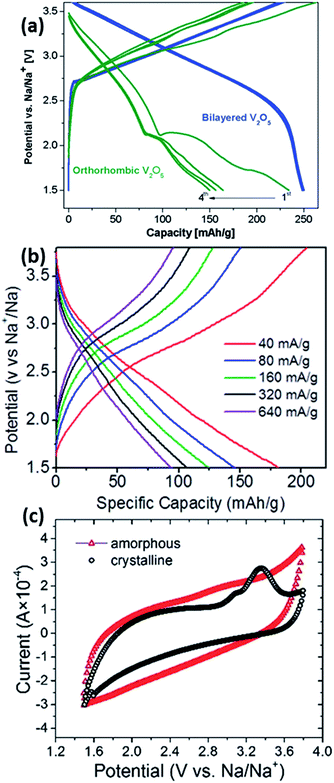 | ||
| Fig. 9 (a) Electrochemical charge–discharge profiles of orthorhombic vs. bilayered V2O5 at a current rate of 20 mA g−1 (ref. 80) (b) galvanostatic charge–discharge profiles of orthorhombic V2O5 at different current rates83 (c) CV curves of amorphous vs. crystalline V2O5 at 1.0 mV s−1 (ref. 84) (a) reprinted with permission from ref. 80. Copyright 2012 American Chemical Society (b) reprinted with permission from ref. 83. Copyright 2013 American Chemical Society (c) reproduced from ref. 84 with permission from The Royal Society of Chemistry. | ||
NaV3O8 is one other oxide that has been widely studied as a potential LIB and NIB cathode material.89–91 NaV3O8·xH2O nanowires recorded an initial specific discharge capacity of 169.6 mA h g−1, with a capacity retention of 91.1% after 50 cycles.90 NaV6O15 (Na0.33V2O5) also showed promising performance as a cathode material in NIBs. Liu et al. reported the electrochemical performance of NaV6O15 nanorods synthesized via a hydrothermal method. The nanorods were able to deliver a capacity of 142 mA h g−1 at a current density of 20 mA g−1. However, the cycling performance at the same rate showed almost a 45% capacity decay after 30 cycles.92 NaV6O15 nanoflakes synthesized by He et al. showed a promising performance by exhibiting an initial capacity of 147.7 mA h g−1 at 15 mA g−1, with a capacity retention of 92.2% after 30 cycles.93
2.2. Polyanions and pyrophosphates
Following the successful introduction of LiFePO4 as a cathode material by Goodenough et al., several other chemical groups have also been explored in LIBs. The main reason for the success in LiFePO4 is largely attributed to the strong inductive effect coming from the PO43− anion, resulting in a high operating voltage.94–96 Hence, the ability for the operating voltage to be tailored in polyanion compounds has led to much interest in its sodium counterpart in recent years. The crystal structures of several Na-based polyanions are shown in Fig. 10. The thermodynamically stable form of NaFePO4 (Fig. 10b) exists as the maricite structure, but this is, however, electrochemically inactive due to the lack of a Na diffusion channel compared to the olivine counterpart.97 Metastable olivine NaFePO4 has been reported to have been obtained through a delithiation of LiFePO4 into heterosite structured FePO4, before electrochemical sodiation to yield NaFePO4.98 The reversible intercalation for olivine NaFePO4 differs from that of its olivine LiFePO4 counterpart. During the charging process, two plateaus are observed instead of one, compared to the discharge process, indicating that the sodiation process might go through different electrochemical pathways (Fig. 11a). An intermediate phase of Na0.7FePO4 was observed through XRD analysis. The formation of Na0.7FePO4 as an intermediate helps cushion the large stress induced during the ion insertion/extraction. The difference in mechanism is attributed to the difference in volumetric mismatch between NaFePO4 and Na0.7FePO4 (3.62% volume mismatch), compared to Na0.7FePO4 and FePO4 (13.48% volume mismatch). Hence, during charging, FePO4 will not start to form until all the NaFePO4 have been converted into Na0.7FePO4, thus this is a two-step reaction. However, during discharge, the lattice mismatch between FePO4 and Na0.7FePO4 is already large to begin with, hence the reaction from FePO4 to Na0.7FePO4 and Na0.7FePO4 to NaFePO4 can occur concurrently.99 Oh et al. then tested such a Li–Na electrochemical exchanged NaFePO4, which exhibited a two-step discharge plateau, resulting in an initial capacity of 125 mA h g−1. Cycling of the Na/NaFePO4 cell showed an excellent capacity retention, with ∼110 mA h g−1 being retained after 50 cycles.100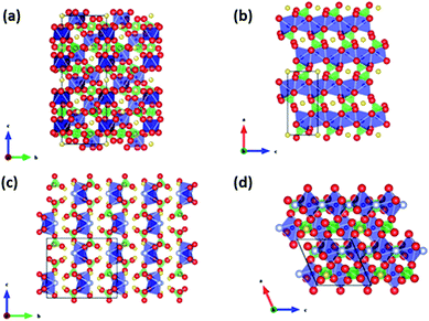 | ||
| Fig. 10 Crystal structure of several polyanionic compounds (Yellow: Na, Blue: V/Fe, Red: O, Grey: F), (a) NASICON Na3V2(PO4)3, (b) olivine NaFePO4, (c) Na2FePO4F, (d) Na2FeSO4F (ref. 13). Copyright 2012 Wiley-VCH Verlag GmbH & Co. KGaA, Weinheim. | ||
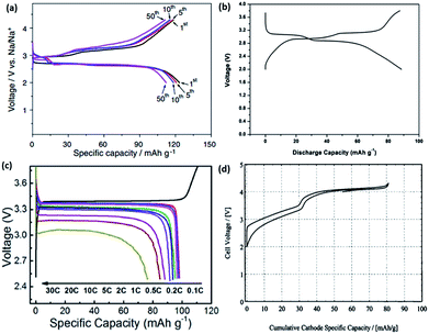 | ||
| Fig. 11 (a) Cycling of an electrochemical Li–Na exchange prepared NaFePO4 at a rate of C/20.100 (b) Galvanostatic charge discharge curve of carbon-coated hollow Na2FePO4F spheres tested at 0.1C.103 (c) Initial charge/discharge curves of Na3V2(PO4)3 tested between 2.5 and 3.8V at various C-rates.107 (d) Electrochemical profile of a Na-based full cell, comprising hard carbon/NaVPO4F, with a reversible capacity of 80 mA h g−1 when cycled between 2.0 and 4.3V.104 (a) Reprinted with permission from ref. 100. Copyright 2012 Elsevier (b) reprinted with permission from ref. 103. Copyright 2013 Elsevier (c) reprinted with permission from ref. 107. Copyright 2014 Elsevier (d) reprinted with permission from ref. 104. Copyright 2003 The Electrochemical Society. | ||
Fluorophosphates have also been studied in both LIBs and NIBs. Iron-based fluorophosphates were first reported by Ellis et al. for LIB applications in 2007.101 Recham et al. compared the performance of different Na-based fluorophosphates compounds synthesized using ionic liquids as templates at low temperatures. In this method, both the morphology and narrow particle size could be accurately controlled. Despite having the same synthesis method for both Na2FePO4F and Na2MnPO4F, their structures differ largely from one another. Na2FePO4F exists in a layered structure where Na+ occupies the space between the layers of the FeO4F2 octahedra and PO4 tetrahedra (Fig. 10c). Comparatively, Na2MnPO4F forms a tunnel structure with Mn2F2O8 chains linked by tetrahedra PO4. While the nanosized Na2FePO4F showed a considerable reversible intercalation of 0.8 mol of Na when cycled between 1.5 and 4.3 V vs. Na+/Na, Na2MnPO4F showed no reversible capacity, even when cycled within the same voltage range.102 Langrock et al. also synthesized carbon-coated hollow Na2FePO4F spheres via a spray pyrolysis. The electrochemical process exhibited two plateau profiles at 3.1 V and 2.9 V, and recorded a discharge capacity of 89 mA h g−1 at a current density of C/10 (Fig. 11b). In addition, the hollow Na2FePO4F spheres demonstrated excellent cyclability, with a capacity retention of 80% (60 mA h g−1) after 750 cycles. The excellent performance could be attributed to the design of the material that allows for rapid ion diffusion, as well as good structure integrity during cycling.103 NaVPO4F prepared by a solid-state synthesis was first introduced by Barker et al. in 2003. A reversible alkali intercalation results in the formation of VPO4F derived with the V3+/V4+ redox couple, as shown in Fig. 11d. A full cell was assembled using hard carbon as the anode and NaVPO4F as the cathode, which delivered a reversible capacity of 80 mA h g−1, with an average discharge potential of 3.7 V.104 Park et al. recently reported novel Na1.5VPO4.8F0.7 with a high redox potential (3.8 V vs. Na+/Na) and a high theoretical energy density (600 W h kg−1), as a result of tailoring the polyanionic group.105 In addition, ex situ XRD was employed to understand the volume change during the phase transformations, of which a value of 2.9% was obtained, which is close to the first principal calculation of 3.1%. The extremely small volume change during the phase transformations results in the material being extremely stable during the charge–discharge processes.106
NASICON (Na+ superionic conductor)-type materials have been extensively studied as solid electrolytes in Na–S batteries. Delmas et al. first reported reversible Na+ intercalation with a NASICON-type NaTi2(PO4)3 in 1987.108 Since then, the insertion of host materials with the general formula AxM2(XO4)3 (where A = Li, Na; M = V, Fe, Mn, Co, and X = P, S, W) have been extensively studied for both LIB and NIB applications. Na3V2(PO4)3 has been investigated as a prospective cathodic material for NIBs. It comprises a 3D framework of PO4 tetrahedra and VO6 octahedra, as shown in Fig. 10a. However, the electrochemical performance of pure Na3V2(PO4)3 is relatively poor because of the poor intrinsic electronic conductivity. Jian et al. were first to implement a thin conductive carbon coating (6 nm) on Na3V2(PO4)3 with ball-milling and by subsequent Ar-thermal treatments. The CV profile indicated two significant electrochemical reactions at 3.4 V and 1.63 V vs. Na+/Na. The composite exhibited reversible capacities of 90.9 mA h g−1 after 10 cycles when cycled between 2.7 and 3.8 V; while, 60 mA h g−1 was recorded after 50 cycles within a voltage window between 1.0 and 3.0 V.109 Na3V2(PO4)3/C composite prepared from a solid-state glucose-assisted reduction method displayed a voltage plateau at 3.4 V vs. Na+/Na, with a recorded initial capacity of 98 mA h g−1 when cycled between 2.5 and 3.8 V (Fig. 11c).107 Nonetheless, the low C.E. remains a problem with the Na3V2(PO4)3/C composite in NaClO4/PC electrolyte. Several other electrolytes have been explored as alternatives, and it was found that the sodium bis(fluorosulfonyl) imides (NaFSI) salt demonstrated the best performance. In contrast, it was also found that Na3V2(PO4)3/C with a lower carbon content performs much better in NaFSI electrolyte. NaFSI/PC demonstrated the best performance with an initial coulombic efficiency of 98.7% and 99.8% in subsequent cycles. This is much higher compared to NaClO4/PC (82% initial/91% subsequent), NaBF4/PC (94.4% initial/98% subsequent), NaPF6/EC + DEC (96.3% initial/99% subsequent) and NaFSI/EC + DEC (98% initial/98.2% subsequent) electrolytes.110 Characterization techniques, including Annular bright field (ABF), scanning transmission electron microscopy (STEM) and solid-state NMR, were employed to elucidate the charge/discharge mechanism of Na3V2(PO4)3. It was observed that two coordination environments (6b, M1 and 18e, M2) exist in Na3V2(PO4)3, while only a single Na site (6b, M1) exists in NaV2(PO4)3, which correlates to a direct M2–M2 ion conduction pathway present during the charge process; whereby up to two Na+ can be extracted from the M2 site, while the Na ions in the M1 site remain intact in Na3V2(PO4)3.111
A mixed polyanionic and pyrophosphate cathode material was studied by Kang's group via both a first principle calculation and experimentally. Na4Fe3(PO4)2(P2O7) was synthesized through a conventional solid-state method, and delivered an energy density of 380 W h kg−1. Mössbauer spectroscopy (Fig. 12a) revealed the deinsertion of up to three Na ions from Na4Fe3(PO4)2(P2O7) to NaFe3(PO4)2(P2O7) during charging, with the Fe2+/Fe3+ redox couple being active (Fig. 12b).29,112 Further analyses via in situ and ex situ XRD, neutron diffraction and X-ray absorption spectroscopy demonstrated that the electrochemical reaction in Na4Fe3(PO4)2(P2O7) results in only a small volume change of 4%. The PITT results showed a single plateau during the discharge process (Fig. 12c), indicating a single phase topotactic reaction. Additionally the strong framework, comprising of polyanion and pyrophosphate anions, makes the structure both physically and thermally stable.112
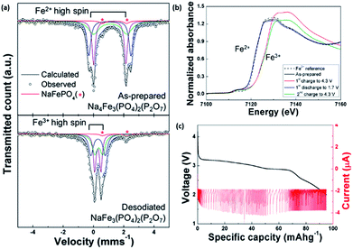 | ||
| Fig. 12 (a) Mössbauer spectra of NaxFe3(PO4)2(P2O7) (x = 1, 4). The observed and calculated patterns are present as black circles and lines, respectively, in the Mössbauer spectrum. The blue, green and purple lines represent the three distinct iron sites. The red line shows the Fe2+ component in the NaFePO4 impurity; this peak does not change during the desodiation process29 (b) XANES spectra of the initial and end states of NaxFe3(PO4)2(P2O7) (x = 1, 4). (c) PITT measurement of Na4Fe3(PO4)2(P2O7) during discharge at a cut-off current corresponding to the C/50 rate112 (a) reprinted with permission from ref. 29. Copyright 2012 American Chemical Society (b and c) reprinted with permission from ref. 112. Copyright 2013 American Chemical Society. | ||
Recently, sodium-based pyrophosphates (Na2MeP2O7 where Me = Fe, Mn or Co) have been reported to be a group of prospective cathodic materials for NIBs.113–116 Barpanda et al. was the first to study Na2FeP2O7 pyrophosphate synthesized via a simple solid-state synthesis method. Electrochemical cycling at a rate of C/20 exhibited a reversible capacity of 82 mA h g−1 within a potential window of 2.0–4.0 V vs. Na+/Na. Mössbauer spectroscopy of Na2FeP2O7 indicated that Fe2+ ions reside in two distinct sites within the crystal structure, and which oxidize to Fe3+ during charging.117 A novel polymorph, β-Na2MnP2O7, was synthesized first by a solid-state method and followed by carbon coating. The assembled half-cells exhibited a reversible discharge capacity of about 80 mA h g−1 at a rate of C/20. However, the rate capability of Na2MnP2O7 has yet to be determined.118 Likewise, Na2CoP2O7 was also synthesized via a solid-state synthesis and carbon coating by Barpanda et al. Electrochemical cycling yielded a similar capacity of 80 mA h g−1 within a voltage window of 3 V.119 Despite the novelty of such sodium-based pyrophosphate materials, the low capacity, cyclability and stability remain as major obstacles to be overcome.
2.3. Organic materials
Novel multifunctional organic compounds have also been studied as prospective electrode materials in NIBs. Sakaushi et al. successfully demonstrated a bipolar porous organic electrode (BPOE) comprising benzene rings and triazine rings in a two-dimensional (2D) structure. The porous organic electrode was able to deliver energy and a power density of up to 500 W h kg−1 and 10 kW kg−1, respectively. Such performance is comparable to that of the oxides and polyanion cathode materials.55,120 In addition, BPOE is a unique bipolar material with a p-dopable region ([C3N3x+(ClO4−)x] + xNa+ + xe− → (C3N3) + xNa+ClO4−) at above OCV (2.8 V) and an n-dopable ((C3N3) + yNa+ + ye− → [C3N3y−(Na+)y]) region at below the OCV, thus giving rise to a wide potential and energy density (Fig. 13). Moreover, cyclability of the half-cell remained at 80% for over 7000 cycles.121 An all-organic symmetric NIB was demonstrated with the use of a novel tetrasodium salt of 2,5-dihydroxyterephthalic acid (Na4DHTPA (Na4C8H2O6)) as both a cathode and anode material. Charge storage for the cathode occurs via a 2-electron redox process (Fig. 14a) in the enolate and quinonoid carbonyl group. Na4DHTPA was able to provide a capacity of 180 mA h g−1 when cycled between a voltage range of 1.6 and 2.8 V vs. Na+/Na in 1 M NaClO4 (EC![[thin space (1/6-em)]](https://www.rsc.org/images/entities/char_2009.gif) :
:![[thin space (1/6-em)]](https://www.rsc.org/images/entities/char_2009.gif) DMC 1
DMC 1![[thin space (1/6-em)]](https://www.rsc.org/images/entities/char_2009.gif) :
:![[thin space (1/6-em)]](https://www.rsc.org/images/entities/char_2009.gif) 1) electrolyte. A full cell was assembled with Na4DHTPA as both the cathode and anode. The galvanostatic charge–discharge curves are shown in Fig. 14b. The full cell was able to deliver an estimated energy density of 65 W h kg−1 (taking into consideration the cell components), with an average discharge voltage of 1.8 V. The cyclability over 100 cycles showed a capacity retention of 76% at a 0.1C rate, and the coulombic efficiency remained stable at 99% after the initial cycles (Fig. 14c).122
1) electrolyte. A full cell was assembled with Na4DHTPA as both the cathode and anode. The galvanostatic charge–discharge curves are shown in Fig. 14b. The full cell was able to deliver an estimated energy density of 65 W h kg−1 (taking into consideration the cell components), with an average discharge voltage of 1.8 V. The cyclability over 100 cycles showed a capacity retention of 76% at a 0.1C rate, and the coulombic efficiency remained stable at 99% after the initial cycles (Fig. 14c).122
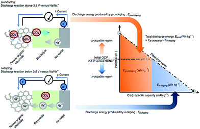 | ||
| Fig. 13 Energy storage mechanism (p-undoping and n-doping) of organic BPOE in a discharge process121 reprinted with permission from Macmillan Publishers Ltd.: (Nat. Commun.) (ref. 121), Copyright 2013. | ||
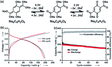 | ||
| Fig. 14 (a) Schematic of redox reactions between Na6C8H2O6/Na4C8H2O6 and Na4C8H2O6/Na2C8H2O6 (b) galvanostatic charge/discharge profiles of full cells assembled with Na4C8H2O6 as both the cathode and anode. (c) Cycling and coulombic efficiency under a current density of 19 mA g−1 (ref. 122). Copyright 2014 Wiley-VCH Verlag GmbH & Co. KGaA, Weinheim. | ||
Several dianhydride-based polyimides (PI) were also investigated by Wang et al. as organic cathodes for NIBs. A simple one-pot synthesis comprising polycondensation followed by imidization was employed for various dianhydride (pyrometallic dianhydride (PMDA), 1,4,5,8-naphthalenetetracarboxylic dianhydrides (NTCDA), perylene 3,4,9,10-tetracarboxylic dianhydride (PTCDA)) and diamines (with varying alkyl chains from C2 to C4). A correlation could be drawn from tuning the individual dianhydride and diamine groups. When the aromatic group varied from PMDA, NTCDA and PTCDA, the average discharge voltage varied from 1.73 to 1.89 and 1.94 V, respectively. This is attributed to the difference in the lowest unoccupied molecular orbital (LUMO) energy level in the presence of different electron withdrawing aromatic groups. Likewise, heavier alkyl chain groups in the polyimide resulted in a lower overall gravimetric energy density. Amongst the different permutations, PTCDA-PI2 had the most stable performance, with exceptional cycling stability and a capacity retention of 87.5%, even after 5000 cycles, owing to its unique polymer structure composed of interconnecting alkyl chains and PTCDA that prohibits unwanted dissolution into the electrolyte. Furthermore, the maximum energy and power density achievable in PTCDA-PI2 were 285 W h kg−1 and 20.99 kW kg−1, respectively.122
2.4. Prussian blue analogues
Several Prussian blue analogues have been studied for application as a cathode material in NIBs.123–128 Prussian blue comprises an open framework capable of accommodating the insertion of alkali ions.Its analogues (NaxMFe(CN)6, where M = Fe, Co, Ni and other transition metals) have been widely explored as potential Na storage cathode materials, owing to their high capacity following two electron redox reactions.126 A schematic of their crystal structure is shown in Fig. 15a. The crystal structure of such Prussian blue analogues follows the general formula of AxM[D(CN)6]·nH2O, where A = alkali metal ion, M = N-coordinated transition metal cation, and D = C-coordinated transition metal cation. While the activation energy for alkali insertion/desinsertion in oxoperovskites is considered to be too high, replacement of the O2− anions with CN− ions helps weaken the bonding with Na+, thus reducing the overall activation energy.127 The number of Na+ intercalated could vary from 0 to 2, where the overall charge neutrality would be maintained by the reduction of transition metals.124
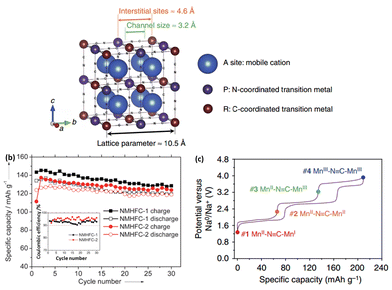 | ||
| Fig. 15 (a) Schematic illustration of open framework cubic Prussian blue analogues126 (b) cycling performance and coulombic efficiency of Na1.72MnFe(CN)6 and Na1.40MnFe(CN)6 (ref. 127) (c) galvanostatic charge and discharge curves of sodium manganese hexacyanomanganate@C/5.126 (a and c) Reprinted with permission from Macmillan Publishers Ltd.: (Nat. Commun.) (ref. 126), Copyright 2014. (b) Copyright 2013 Wiley-VCH Verlag GmbH & Co. KGaA, Weinheim. | ||
Goodenough et al. were first to demonstrate the use of hexacyanides in organic system NIBs. Various KMFe(CN)6 (where M = Mn, Fe, Co, Ni and Zn) compounds were synthesized, with their electrochemical performance studied. Among the different compositions, KFeFe(CN)6 had the highest capacity of 70 mA h g−1 with a redox potential of approximately 3.7 V vs. Na+/Na. This was attributed to the enhancement of the crystal field splitting, which stabilizes the low-spin state Fe(III): 3d5 configuration to the octahedral site of the C atom, while the Fe(II): 3d6 configuration is coordinated to N atoms in its high-spin state.129 Subsequently, rhombohedral Na1.72MnFe(CN)6 and cubic Na1.4MnFe(CN)6 were synthesized at room temperature. In both cases, Mn is coordinated by N and is in the high-spin state, while Fe is coordinated by C and is in a low-spin state. The electrochemical profiles also showed no influence of structural differences on the reaction potentials. At 0.1C, a discharge capacity of 134 mA h g−1 was obtained when cycled between 2.0 and 4.2 V vs. Na+/Na. Excellent cyclability was also observed, with a capacity retention of about 90% after 30 cycles (Fig. 15b).127
Wu et al. studied single crystal FeFe(CN)6 nanoparticles capable of achieving up to 120 mA h g−1, with an amazing capacity retention of 87%, even after 500 cycles.123 A modified NaZnFe(CN)6 capable of accommodating up to two Na+ ions was investigated for its cathodic properties. However, a reversible capacity of only 56.4 mA h g−1 was obtained. Additionally, it was observed that the electrochemical performance varied largely with the choice of electrolyte, with 1 M NaPF6 in EC![[thin space (1/6-em)]](https://www.rsc.org/images/entities/char_2009.gif) :
:![[thin space (1/6-em)]](https://www.rsc.org/images/entities/char_2009.gif) DMC (1
DMC (1![[thin space (1/6-em)]](https://www.rsc.org/images/entities/char_2009.gif) :
:![[thin space (1/6-em)]](https://www.rsc.org/images/entities/char_2009.gif) 1 v/v) exhibiting a capacity retention of 94.6% compared to 85.2% in 1 M NaClO4 in PC.125 Nanocrystalline NaFe[Fe(CN)6] was synthesized from a simple but slow technique with a low water content. The electrochemical performance was much better compared to low crystalline NaFe[Fe(CN)6]. Ex situ XRD was used to understand the structure evolution throughout the sodiation process. The two electron reaction was observed with structure changes from cubic FeIII[FeIII(CN)6] to cubic NaFeIII[FeII(CN)6], and subsequently to rhombohedral Na2FeII[FeII(CN)6].128
1 v/v) exhibiting a capacity retention of 94.6% compared to 85.2% in 1 M NaClO4 in PC.125 Nanocrystalline NaFe[Fe(CN)6] was synthesized from a simple but slow technique with a low water content. The electrochemical performance was much better compared to low crystalline NaFe[Fe(CN)6]. Ex situ XRD was used to understand the structure evolution throughout the sodiation process. The two electron reaction was observed with structure changes from cubic FeIII[FeIII(CN)6] to cubic NaFeIII[FeII(CN)6], and subsequently to rhombohedral Na2FeII[FeII(CN)6].128
Very recently, Cui et al. introduced sodium manganese hexacyanomanganate (Na2MnII[MnII(CN)6], which was capable of delivering a capacity of up to 209 mA h g−1 (Fig. 15c). Additionally, the rate capability was excellent, with a discharge capacity of 157 mA h g−1 at 5C. Synchrotron XRD was carried out to elucidate the redox mechanism and how the high capacity was achievable. It was found that sodiation of the material causes a change in the crystal structure gradually from cubic to a distorted monoclinic structure, which eventually allows the accommodation of up to three sodium ions. It should be noted that the electrochemical measurements were carried out in a flooded three-electrode cell, with a Ag/AgCl mesh pseudo-reference electrode coupled to a ferrocene (Fc+/Fc) redox couple.126
2.5. Other potential cathode materials
Phosphate-based polyanion cathode materials have been well investigated over the past years. As such, modification of the polyanion groups (e.g. replacing phosphate (PO43−) with sulphate (SO42−)) results in a varying inductive influence within the framework. Compared to NaFePO4 (2.7 V vs. Na+/Na), the novel Na2Fe2(SO4)3 had a much higher Fe2+/Fe3+ redox couple of 3.8 V vs. Na+/Na. The electrochemical profile of Na2Fe2(SO4)3 cycled between 2.0 and 4.5 V (vs. Na+/Na) recorded a specific capacity of about 100 mA h g−1. Even at a high rate of 20C, a reversible capacity of approximately 50 mA h g−1 has been recorded. As shown in Fig. 16, Na2Fe2(SO4)3 records the highest working potential amongst Fe-based cathodes for NIBs. This in turn would result in a high energy density (theoretical value of 540 W h kg−1), which would be a key factor for overcoming mileage problems in EVs. Moreover, the precursors, Na, Fe and S are among the most abundant materials on earth, which makes commercialization more feasible.130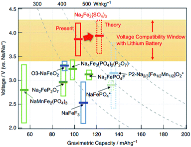 | ||
| Fig. 16 An overall comparison of Fe-based cathode materials in NIBs.130 Reprinted with permission from Macmillan Publishers Ltd.: (Nat. Commun.) (ref. 130), Copyright 2014. | ||
TiS2 was studied early on in the 1970s and 80s as an intercalation host for both LIBs and NIBs. Nagelberg and Worrell studied the thermodynamics of TiS2via the intercalation of sodium ions into the layered structure. It was found that the lithium-intercalated TiS2 possesses a more negative standard free energy of intercalation compared to sodium-intercalated TiS2. Additionally, the compositional variation of the sodium chemical potential in NaxTiS2 exhibits two plateaus, which indicates the presence of two-phase regions.131 Newman and Klemann studied the intercalation of Na ions into TiS2 in a dioxolane solution of sodium triethyl (N-pyrrolyl) borate at room temperature. Complete discharge at a current density of 2.5 mA cm−2 resulted in the formation of Na0.8TiS2. Two discharge plateaus could be observed during the formation of NaxTiS2, particularly at ∼1.9 V (0 ≤ x ≤ 0.4) and at ∼1.5 V (0.4 ≤ x ≤ 0.8), which is in agreement with Nagelberg's results. However, the cycling performance of the cathode was rather poor and the theoretical energy density was only 144 W h kg−1, compared to 480 W h kg−1 in Li–TiS2 systems.132 In the 1970–80s, several reviews on electrode materials for SIB had already reported. Whittingham reviewed different types of intercalation cations in several transition metal dichalcogenides,133 while Abraham summarized the electrochemical performance of transition metal dichalcogenides in rechargeable sodium systems.134 Readers are advised to refer to the reviews for a more detailed overview.
Popular choices of commercially available LIB cathode materials, such as LiCoO2 and LiFePO4, are generally made up of oxygen containing compounds. A major disadvantage as such in LiCoO2 (charged-state) is the decomposition at elevated temperature to release oxygen, which then exothermally reacts with organic electrolytes and can thus raise safety issues.135,136 Metal fluorides have been considered as an alternative, albeit with poor electronic conductivity, owing to the large bandgap induced by the high ionic characteristic of the metal–halogen bond. However, their large ionic nature should theoretically help in providing a higher voltage output when used as electrode materials.137
Gocheva et al. reported the electrochemical performance of several sodium metal fluorides (NaMF3 where M = Ni, Mn, Fe) prepared via mechanochemical synthesis. When tested in a half-cell configuration, NaFeF3 was able to exhibit a capacity of 128 mA h g−1 when cycled between 1.5 and 4.0 vs. Na+/Na. However, the electrolyte decomposition cut-off voltage limited the electrochemical performances of NaMnF3 and NaNiF3.138 Liquid phase synthesis using an organic solvent produced highly dispersed uniform NaFeF3 nanoparticles. The particle sized could be controlled by using different oleic acid/oleyamine ratios. It can be observed from Fig. 17a that smaller-sized particles delivered a higher capacity, especially at high current densities. When tested at 0.01C, discharge capacities within a range of 170–181 mA h g−1 could be obtained.139 DFT calculations showed that Na0.5FeF3 is the only energetically stable phase, resulting in two voltage plateaus at 2.63 V when 1 ≥ x ≥ 0.5 and 2.82 V during 0.5 ≥ x ≥ 0.140
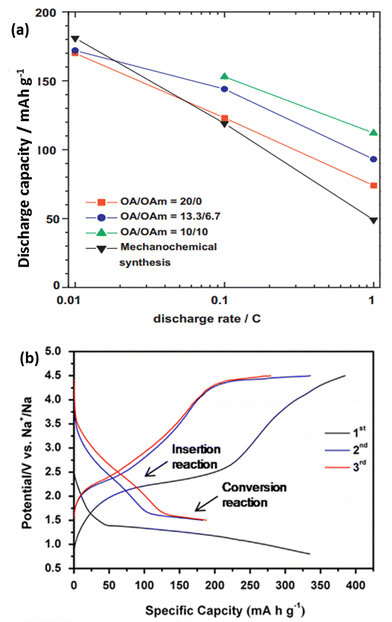 | ||
| Fig. 17 (a) Variation of the discharge capacity and current rates of different NaFeF3 particles synthesized from a liquid phase synthesis.139 (b) In situ electrochemical activation of the FeF2–rGO composite to form FeF3–Fe–rGO during the first cycle, followed by its subsequent charge–discharge curves142 (a) reprinted with permission from ref. 139. Copyright 2011 Elsevier (b) reprinted with permission from ref. 142. Copyright 2014 Elsevier. | ||
The perovskite-type metal trifluoride FeF3 was also explored as a potential cathode material for NIB. Nishijima reported ball-milled FeF3 with 25% acetylene black for both Li and Na systems. When tested in NIB, a reversible capacity of ∼100 mA h g−1 could be obtained, with an average discharge voltage of 2.2 V. Other metal fluorides, including TiF3, MnF3, CoF3, were prepared using the same methodology, and were tested.141 By homogeneously distributing FeF3 within a matrix of metallic Fe and reduced graphene oxide (rGO) through an in situ method, the FeF3–Fe–rGO composite was able to deliver a high capacity of ∼180 mA h g−1 when cycled at 20 mA g−1 (Fig. 17b). By allowing poorly conductive FeF3 to be in intimate contact with highly conductive Fe and rGO, a good rate capability and long cyclability could be achieved in the overall compound.142 Nanocellular carbon foams have also been recently studied as a cathode material in NIBs. Their energy storage mechanism is attributed to the surface reactions between Na+ and oxygen-containing functional groups on the surface of the carbon foams (i.e. –C![[double bond, length as m-dash]](https://www.rsc.org/images/entities/char_e001.gif) O + Na+ + e− ↔ –C–O–Na). The relationship between the peak current and scanning rates shows a linear profile, indicating that the redox reaction is limited to the surface and is not diffusion limited. The carbon foam was able to deliver a reversible specific capacity of 152 mA h g−1 when tested at 100 mA g−1, along with a capacity retention of 90% over 1600 cycles. Despite the excellent electrochemical performance, the volumetric energy density still remains a problem in such carbon-based compounds. In addition, for commercialization to be possible, an anode prepared in the charged state is necessary.143
O + Na+ + e− ↔ –C–O–Na). The relationship between the peak current and scanning rates shows a linear profile, indicating that the redox reaction is limited to the surface and is not diffusion limited. The carbon foam was able to deliver a reversible specific capacity of 152 mA h g−1 when tested at 100 mA g−1, along with a capacity retention of 90% over 1600 cycles. Despite the excellent electrochemical performance, the volumetric energy density still remains a problem in such carbon-based compounds. In addition, for commercialization to be possible, an anode prepared in the charged state is necessary.143
3. Negative electrode materials
In current commercialized LIBs, both electrodes employ insertion host materials. Despite the fact that lithium metal has the lowest reduction potential (−3.04 vs. S.H.E.) and is able to provide a theoretical capacity of up to 3840 mA h g−1, it is avoided, mainly due to safety issues resulting from the growth of dendrites that could potentially lead to a short circuit of the cell.17,144 Compared with lithium, these issues are even more problematic with sodium, due to its much higher reactivity with organic solvents; while additionally, sodium has a low melting point (97.7 °C) which is also a drawback related to safety issues when used in anodes for room-temperature batteries.14 Hence, it is necessary and critical to find a suitable sodium host material with a low redox potential as the anode for NIBs. So far, various materials have been exploited for this purpose, including carbonaceous materials, sodium alloys, metal oxides/sulfides, phosphorus and phosphides.3.1. Carbonaceous materials
Graphite has been the most widely used anode material in commercial LIBs. It has a relatively high capacity (∼350 mA h g−1), low potential plateau (∼0.1 vs. Li+/Li) and high stability. A LIB composed of a graphite anode and an appropriate cathode, such as LiCoO2, could offer high energy density, high energy efficiency and long cycle life. However, it has been proven that a very small amount of sodium can insert into graphite, probably because the process is not thermodynamically favorable.31,145,146To find an alternative anode for NIBs, amorphous carbons have been investigated thoroughly. Early work has demonstrated the sodium storage behaviour in varying textured amorphous carbons pyrolyzed from different precursors and at different temperatures.147–149 Among these, several hard carbons have exhibited a high reversible capacity of close to 300 mA h g−1.149–153 Hard carbon is known to be a type of non-graphitizable amorphous carbon with inherent nanoporosity due to the random stacking of graphene sheets and pores on the order of size of the graphene sheets.154,155 The discharge/charge voltage profiles of hard carbon for sodium storage are similar to lithium systems, with an inclined region at a relatively high potential window and a plateau at low potential close to that of sodium metal (Fig. 18a and b). Thus, lithium insertion mechanisms in hard carbon have been similarly proposed for sodium insertion, i.e. the sloping region was attributed to sodium insertion into parallel layers of graphene sheets; and the low-potential plateau was attributed to the pore-filling of sodium.151 Such mechanisms were further confirmed by an NMR study on electrochemically sodiated hard carbon.156 Although early reports on hard carbon have shown poor cyclability and an insufficient initial coulombic efficiency (usually lower than 80%), the initial reversible capacity of ∼300 mA h g−1 is significant and close to the lithium intercalation in graphite, thus rendering it a promising anode for sodium-ion batteries.
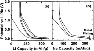 | ||
| Fig. 18 Voltage profiles of lithium (a) and sodium (b) storage in hard carbon149 reprinted with permission from ref. 149. Copyright 2001 The Electrochemical Society. | ||
One of the main challenges to the poor cyclability is probably associated with the high reactivity of sodiated hard carbon with electrolytes. When carbonaceous materials are used in LIBs with the electrolyte LiPF6 in ethylene carbonate (EC):diethyl carbonate (DEC), or, LiPF6 in EC![[thin space (1/6-em)]](https://www.rsc.org/images/entities/char_2009.gif) :
:![[thin space (1/6-em)]](https://www.rsc.org/images/entities/char_2009.gif) dimethyl carbonate (DMC), a stable solid electrolyte interface (SEI) layer between the materials and electrolyte, which contains several inorganic salts, such as LiF and Li2CO3, is formed because of decomposition of the LiPF6 and electrolyte solvents during the initial discharge.157,158 Such a stable SEI layer serves as one of the main contributions to the stable cycling behaviour. However, in the case of NaPF6, there may be a lack of formation of a stable SEI layer even when using the same solvents and this thus results in its poor cyclability.31,159,160 Optimization of the electrolytes has been carried out by several groups and it was reported that when electrolytes such as NaClO4 in PC and NaPF6 in EC
dimethyl carbonate (DMC), a stable solid electrolyte interface (SEI) layer between the materials and electrolyte, which contains several inorganic salts, such as LiF and Li2CO3, is formed because of decomposition of the LiPF6 and electrolyte solvents during the initial discharge.157,158 Such a stable SEI layer serves as one of the main contributions to the stable cycling behaviour. However, in the case of NaPF6, there may be a lack of formation of a stable SEI layer even when using the same solvents and this thus results in its poor cyclability.31,159,160 Optimization of the electrolytes has been carried out by several groups and it was reported that when electrolytes such as NaClO4 in PC and NaPF6 in EC![[thin space (1/6-em)]](https://www.rsc.org/images/entities/char_2009.gif) :
:![[thin space (1/6-em)]](https://www.rsc.org/images/entities/char_2009.gif) PC were used, a long cycling performance of up to more than a hundred of cycles could be achieved (Fig. 19a and b).161,162 Moreover, it has been reported that additives such as fluoroethylene carbonate (FEC) that can form more stable SEI layers can also enhance the stability of carbon electrodes.163 Recently, various nanostructured carbonaceous materials were examined as anodes for sodium-ion batteries, and it was found that the sodium storage properties, including the cyclability and rate capability, largely depended on the carbon structures/architecture. The first carbon materials with high rate capabilities were prepared by a templating method by Wenzel et al. The materials owned a hierarchical porous structure which allowed easy accessibility to the electrolyte over the interconnected pores and a short sodium ion diffusion distance in the bulk. As a result, a high rate capability, with a capacity of ∼100 mA h g−1 at a rate of 5C (1860 mA g−1) could be achieved.164 Tang et al. reported that hollow carbon nanospheres with mesoporous carbon shells of thicknesses of ∼12 nm could also have a high rate capability, and that even at a current density of 10 A g−1, a capacity of ∼50 mA h g−1 could still be obtained. Furthermore, these nanospheres also showed a long cycling performance, with insignificant fading after more than 100 cycles.165 Cao et al. obtained a high-rate carbonaceous material that also had a long cycling performance based on hollow carbon nanowires with thin carbon walls, as shown in Fig. 19c–e.166 A similar concept of porosity and short ion diffusion distance was reported in subsequent publications.167,168 These materials, while on the one hand, exhibited enhanced electrochemical performance, especially in terms of rate capability; on the other hand, they usually had a rather low initial coulombic efficiency – in some cases, even lower than 50%. For example, an efficiency of 42% was recorded for Tang's hollow spheres, and 51% for Cao's hollow nanowires. This is because of the irreversible formation of SEI layers on materials with large surface areas, resulting from their porosity and nanostructures. Such a low coulombic efficiency would usually be a drawback preventing them from practical applications. For enhanced sodium storage properties, many authors also emphasized the feature of enlarged graphene interlayer spacing and claimed that this benefited sodium insertion, because sodium ion have a relatively larger radius (1.02 Å) compared to lithium ions (0.79 Å).165–170 Very recently; a remarkable improvement was achieved by Hu et al. based on a hydrothermally carbonized sucrose method, which was further pyrolyzed at high temperature, where the surface was coated with soft (graphitizable) carbon. The graphitized carbon coating could improve the 1st cycle coulombic efficiency from 53% to 83%. Using a pyrolysis temperature of 1600 °C, a long plateau capacity of 220 mA h g−1 could be obtained. The full cell capability was demonstrated using 1600 °C pyrolysed carbon as anode and P2-Na2/3Ni1/3Mn2/3O2 as the cathode. The theoretical capacity of this system was estimated to be 200 W h kg−1. This performance is believed to be closest to the requirements for practical devices.171
PC were used, a long cycling performance of up to more than a hundred of cycles could be achieved (Fig. 19a and b).161,162 Moreover, it has been reported that additives such as fluoroethylene carbonate (FEC) that can form more stable SEI layers can also enhance the stability of carbon electrodes.163 Recently, various nanostructured carbonaceous materials were examined as anodes for sodium-ion batteries, and it was found that the sodium storage properties, including the cyclability and rate capability, largely depended on the carbon structures/architecture. The first carbon materials with high rate capabilities were prepared by a templating method by Wenzel et al. The materials owned a hierarchical porous structure which allowed easy accessibility to the electrolyte over the interconnected pores and a short sodium ion diffusion distance in the bulk. As a result, a high rate capability, with a capacity of ∼100 mA h g−1 at a rate of 5C (1860 mA g−1) could be achieved.164 Tang et al. reported that hollow carbon nanospheres with mesoporous carbon shells of thicknesses of ∼12 nm could also have a high rate capability, and that even at a current density of 10 A g−1, a capacity of ∼50 mA h g−1 could still be obtained. Furthermore, these nanospheres also showed a long cycling performance, with insignificant fading after more than 100 cycles.165 Cao et al. obtained a high-rate carbonaceous material that also had a long cycling performance based on hollow carbon nanowires with thin carbon walls, as shown in Fig. 19c–e.166 A similar concept of porosity and short ion diffusion distance was reported in subsequent publications.167,168 These materials, while on the one hand, exhibited enhanced electrochemical performance, especially in terms of rate capability; on the other hand, they usually had a rather low initial coulombic efficiency – in some cases, even lower than 50%. For example, an efficiency of 42% was recorded for Tang's hollow spheres, and 51% for Cao's hollow nanowires. This is because of the irreversible formation of SEI layers on materials with large surface areas, resulting from their porosity and nanostructures. Such a low coulombic efficiency would usually be a drawback preventing them from practical applications. For enhanced sodium storage properties, many authors also emphasized the feature of enlarged graphene interlayer spacing and claimed that this benefited sodium insertion, because sodium ion have a relatively larger radius (1.02 Å) compared to lithium ions (0.79 Å).165–170 Very recently; a remarkable improvement was achieved by Hu et al. based on a hydrothermally carbonized sucrose method, which was further pyrolyzed at high temperature, where the surface was coated with soft (graphitizable) carbon. The graphitized carbon coating could improve the 1st cycle coulombic efficiency from 53% to 83%. Using a pyrolysis temperature of 1600 °C, a long plateau capacity of 220 mA h g−1 could be obtained. The full cell capability was demonstrated using 1600 °C pyrolysed carbon as anode and P2-Na2/3Ni1/3Mn2/3O2 as the cathode. The theoretical capacity of this system was estimated to be 200 W h kg−1. This performance is believed to be closest to the requirements for practical devices.171
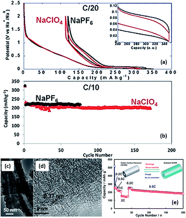 | ||
Fig. 19 (a) First cycle voltage versus capacity profiles for hard carbon electrodes cycled in EC![[thin space (1/6-em)]](https://www.rsc.org/images/entities/char_2009.gif) : :![[thin space (1/6-em)]](https://www.rsc.org/images/entities/char_2009.gif) PC based electrolytes with 1 M of NaClO4 or NaPF6 (recorded at C/20) and (b) discharge capacity versus cycle number for similar cells cycled at C/10 (ref. 162) (c and d) high-resolution TEM images of hollow carbon nanowires, and (e) their rate and cycling properties.166 (a and b) Reproduced from ref. 162 with permission from The Royal Society of Chemistry (c–e) reprinted with permission from ref. 166. Copyright 2012 American Chemical Society. PC based electrolytes with 1 M of NaClO4 or NaPF6 (recorded at C/20) and (b) discharge capacity versus cycle number for similar cells cycled at C/10 (ref. 162) (c and d) high-resolution TEM images of hollow carbon nanowires, and (e) their rate and cycling properties.166 (a and b) Reproduced from ref. 162 with permission from The Royal Society of Chemistry (c–e) reprinted with permission from ref. 166. Copyright 2012 American Chemical Society. | ||
Nitrogen-doped porous carbons were also reported for use as anodes for sodium-ion batteries.172–174 They were able to achieve capacities of ∼300 mA h g−1 and long cycling performances. However, they also exhibited a low initial coulombic efficiency (29–53%). Functionalized N-doped carbon nanofibers are also reported to exhibit excellent electrochemical performance as an anode material in NIBs. A capacity of 134.2 mA h g−1 was maintained after 200 cycles when tested at a relatively high current density of 200 mA g−1, corresponding to a capacity retention of 88.7%. However, a low initial coulombic efficiency of 41.8% was also observed in the work.175 For these materials, a high proportion of the capacity might be due to interfacial storage related to nitrogen doping. Moreover, graphene also remains a promising anode material for sodium-ion batteries. Although the reversible capacity reported so far, based on reduced graphene oxides, is also ∼300 mA h g−1, and with a low coulombic efficiency (20–50%), a study based on first principle calculations has suggested a maximum capacity of higher than 1000 mA h g−1 for defective graphene.176–178
3.2. Sodium alloys
Similar to the alloying reactions in LIBs, several metals, such as tin (Sn) and antimony (Sb), are able to undergo electrochemical alloying reactions with sodium, and thus can provide high capacities in NIBs. A simulation based on Density Functional Theory (DFT) by Chevrier et al. predicted that the electrochemical sodiation of tin involves several phase transitions, including NaSn5, NaSn, and Na9Sn4 phases, that eventually lead to the final formation of Na15Sn4 with a theoretical capacity of 847 mA h g−1 (Fig. 20a).179 The first investigation of such sodium–tin alloying reactions in a sodium cell was reported recently by Komaba et al.180 A large capacity of 878 and 758 mA h g−1 was obtained for the initial discharge and charge processes, respectively, corresponding to a coulombic efficiency of 86%. In addition, similar electrochemical profiles between the theoretical and experimental results were observed.181–183 However, it was also suggested that the first sodiation process of tin occurs via a two-step reaction. This involved a two phase reaction that first forms a Na-poor, amorphous NaxSn alloy (x = ∼0.5), followed by further sodiation into Na-rich amorphous phases, which are then followed by a one phase mechanism to finally form crystalline Na15Sn4.184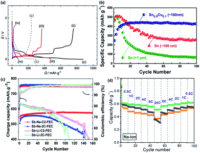 | ||
| Fig. 20 (a) Initial galvanostatic reduction and oxidation curves of (i) hard-carbon with PVdF binder, (ii) Sn–PAA, (iii) Pb–PAA, (iv) Si–PAA, and (v) Sn–PVdF. The hard-carbon electrodes were examined in beaker-type Na cells at 25 mA g−1, and the other electrodes were tested in coin-type Na cells at 50 mA g−1 (ref. 180) (b) reversible discharge capacities of electrodes made of Sn0.9Cu0.1 nanoparticles, Sn nanoparticles, and Sn microparticles. All the electrodes were cycled at 0.2C rate (169 mA g−1).192 (c) Cycling performance of micrometric antimony in Li and Na systems with 5 wt% FEC.193 (d) Cycling and rate performance of antimony with different sizes.194 (a) Reprinted with permission from ref. 180. Copyright 2012 Elsevier (b) reprinted with permission from ref. 192. Copyright 2013 American Chemical Society (c) reprinted with permission from ref. 193. Copyright 2012 American Chemical Society (d) reprinted with permission from ref. 194. Copyright 2014 American Chemical Society. | ||
One drawback from using tin for sodium storage is the large volume expansion (420% volume change) during the formation of Na15Sn4,179 which appears to be even larger than the expansion during the insertion of lithium (260%).185 This large volume change during the sodiation/desodiation causes an instability of the electrodes, and results in the capacity fast fading. This issue of large volume expansion is also present for lithium storage application. In order to improve the stability of Sn, many strategies used in the lithium case have been applied to the sodium case, which includes nanosizing and the preparation of composites materials, such as a tin/carbon composite,186–188 tin-based active/inactive intermetallics (CoSn2 and (Cu6Sn5)1−xCx),189–191 and other composites.181 Carbon and the inactive components within the composites usually serve as a buffering matrix for the volume expansion during the electrochemical reaction. Via an active/inactive strategy, Lin et al. prepared a Sn0.9Cu0.1 composite made of Sn and Cu6Sn5,192 which was able to retain ∼400 mA h g−1 after 100 cycles, as shown in Fig. 20b.
Antimony is another promising element that can undergo an alloying reaction with sodium. It has a theoretical capacity of 660 mA h g−1 with the formation of Na3Sb. Darwiche et al. reported that the intermediate phases during the sodiation/desodiation of antimony were mostly amorphous, in which a competition takes place between the formation of the hexagonal (main) and the cubic polymorphs of Na3Sb at the end of the discharge of the Sb/Na cell.193 Considering the molar volume of Sb (rhombohedral, 18.17 cm3 mol−1) and Na3Sb (hexagonal, 71.43 cm3 mol−1), the volume expansion of this material after sodiation is ∼290%. However, this material seems to be able to exhibit a good cycling performance, with a capacity close to 600 mA h g−1 after 160 cycles, as shown in Fig. 20c. Further optimization using similar strategies as used for tin might lead to an even better performance.195–200 For example, He et al. reported antimony synthesized with a size of ∼20 nm that possessed both a long cycling performance (larger than 600 mA h g−1 after 100 cycles) and high rate capability (∼500 mA h g−1 at a current density of 13.2 A g−1), as shown in Fig. 20d.194
The SnSb intermetallic is also an attractive alternative for sodium storage. Xiao et al. reported a SnSb/C composite with an initial capacity of 544 mA h g−1 and a capacity retention of 80% after 50 cycles. The cyclic voltammetry (CV) results suggested that the alloying and dealloying reactions occur in a sequential manner based on the Sn-rich and Sb-rich phases, similar to that of the SnSb alloy reacting with Li. It was assumed that the sodiation of SnSb proceeds to first form Na3Sb and Sn, followed by the sodiation of Sn into Na15Sn4. By a combination study of XRD and 119Sn and 121Sb Mössbauer spectroscopies, Baggetto et al. reported that the sodiation of SnSb yields hexagonal Na3Sb at a full discharge at higher temperatures (65 and 95 °C), while the room temperature reaction yielded amorphous compounds.201 Ji et al. reported a porous carbon nanofiber-supported SnSb with a relatively lower capacity of ∼400 mA h g−1, but with no visible fading, even after more than 200 cycles.202
Other elements, such as lead (Pb) and germanium (Ge), have also been reported to be able to electrochemically alloy with sodium, and to have a significant capacity.203–205 The theoretical capacity predicted from DFT calculations for lead and germanium are 485 and 369 mA h g−1, respectively.179 Silicon, which alloys with lithium and provides a high capacity of larger than 4000 mA h g−1, only showed a capacity of less than 100 mA h g−1 during sodium storage, although the DFT calculation predicted it should have a sodium capacity of approximately 954 mA h g−1.
In addition to the optimization of alloying materials from a materials point of view, many reports have shown that the optimization of electrolytes could lead to a better battery cycling performance. For instance, the presence of FEC in electrolytes is widely reported to be able to form more stable SEI layers, which is beneficial for the cycling performance;206,207 although, there are also other reports that have shown no significant improvement by adding FEC.208 Moreover, using more stable or conductive binders, such as sodium carboxymethyl cellulose (CMC), poly(acrylic acid) (PAA), or poly(9,9-dioctylfluorene-co-fluorenone-co-methylbenzoic ester) (PFM), in the electrode, instead of the most widely used poly(vinylidene fluoride) (PVDF) binder could improve the stability of electrodes.34,180
3.3. Oxides
One other emerging class of anode material for NIBs belongs to the titanium-based compounds, including TiO2, spinel type Li4Ti5O12, and layered Na2Ti3O7 and Na0.66[Li0.22Ti0.78]O2.TiO2 is well known to be a versatile material that exists in several polymorphs, depending on the respective synthesis technique. The polymorphs exist depending on how the octahedral TiO6 are linked within the structure. Significant advantages which have captured researchers' attention include cheap cost, availability, and that it possesses a low intercalation potential (∼1.5 V vs. Li+/Li). Various sodium storage mechanisms, such as pseudo-capacitance and sodium insertion, have been proposed for this material. Recently, Wu et al. reported that anatase TiO2 could be partially reduced into metallic titanium when discharged to 0.1 V vs. Na+/Na, and is accompanied by the formation of sodium oxide and amorphous sodium titanate. The formation of the metallic titanium was first confirmed by X-ray photoelectron spectroscopy (XPS) analysis, and it was further proposed that the following cycles were based on the insertion/deinsertion of sodium in the newly formed amorphous sodium titanate.209 Xu et al. recently reported the electrochemical performance of anatase TiO2 as an anode in NIBs. Anatase TiO2 comprises a 3D structure with an interconnecting network of zigzag channels of 1D TiO6 octahedra. The mesoporous TiO2 was fabricated using cellulose as the sacrificial template, along with hydrolysis and an annealing treatment. A reversible capacity, as shown in Fig. 21a, of about 150 mA h g−1 could be obtained when cycled between 0.01 and 2.5 V (vs. Na+/Na).210 However, comparative to the intercalation of Li into anatase TiO2, the absence of a well-defined voltage plateau was observed in its Na counterpart. Bronze TiO2 synthesized via a hydrothermal method was also investigated as a potential anode material for NIBs; however, a capacity retention of only 37.8% was recorded after 90 cycles (Fig. 21b).211 Binder-free amorphous TiO2 nanotubes (interior diameter > 80 nm) deposited directly via electrochemical anodization have also been studied as an anode material in NIBs. It was noted that the diameter of the nanotubes play an important role in Na intercalations. For TiO2 nanotubes with an internal diameter of 45 nm, the electrochemical profile remained inactive, compared to nanotubes with an internal diameter of 80 nm, where 150 mA h g−1 of capacity could be achieved after 15 cycles (Fig. 21c).212 Hollandite TiO2 prepared via an oxidation-ion extraction process from K0.21TiO2 was also employed for NIB use. The wide (2 × 2) channels along the [001] direction were thought to help facilitate ion diffusion, as well as to provide a “zero-strain” intercalation behaviour, as per its lithium predecessors. Similarly, a sloping profile resulting in an initial capacity of 280 mA h g−1 was obtained during discharge, but subsequently only 0.25 mol of Na could be extracted (Fig. 21d).213 As observed from all the galvanostatic charge/discharge curves of the TiO2 polymorphs in Fig. 21, the electrochemical profiles lack a flat potential plateau during Na insertion, compared to Li insertion, during reversible reactions. This could suggest a different mechanism present during the reaction.
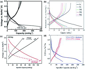 | ||
| Fig. 21 Galvanostatic charge–discharge curve of (a) mesoporous anatase TiO2 cycled between 0.01–2.5 V.210 (b) Hydrothermally synthesized bronze TiO2 cycled between 0.8–3.0 V.211 (c) Amorphous TiO2 cycled between 0.8–2.5 V.212 (d) Hollandite-type TiO2 during the 1st and 2nd cycle213 (a) reproduced from ref. 210 with permission from The Royal Society of Chemistry (b) reproduced from ref. 211 with permission from The Royal Society of Chemistry (c) reprinted with permission from ref. 212. Copyright 2011 American Chemical Society (d) reproduced from ref. 213 with permission from The Royal Society of Chemistry. | ||
Spinel Li4Ti5O12 has been investigated intensively as a “zero-strain” anode for LIBs. Recently, Sun et al. also demonstrated its promising sodium storage behaviour, showing a reversible capacity of ∼150 mA h g−1, with an average plateau at ∼0.9 V vs. Na+/Na, and a first coulombic efficiency of up to 81%. An interesting three-phase reaction (2Li4Ti5O12 + 6Na ↔ Li7Ti5O12 + Na6LiTi5O12) has been proposed for sodium storage of the material, instead of the two-phase mechanism (Li4Ti5O12 + 3Li ↔ Li7Ti5O12) for lithium storage.214–217 Such a mechanism has been supported by DFT calculations and a variety of advanced characterization techniques, such as spherical aberration-corrected scanning transmission electron microscope. The sodium storage behaviour was reported to be highly size dependent, due to the slow diffusion kinetics with an apparent sodium diffusion coefficient of 2.7 × 10⁻¹⁶ cm2 s−1, i.e. five order of magnitudes smaller than that of lithium.217 Thus nanosizing is necessary to achieve high performance.
Senguttuvan et al. first reported layered Na2Ti3O7 as a sodium insertion host for an efficient low voltage anode in 2011. In situ XRD revealed the phase transformation from Na4Ti3O7 to Na2Ti3O7 during discharge of the anode (Fig. 22a–f). A voltage plateau at 0.3 V vs. Na+/Na, resulting in a discharge capacity of approximately 200 mA h g−1, was observed when cycled between 0.01 and 2.5 V (Fig. 22g).218 Pan et al. also studied Na2Ti3O7 prepared via a solid-state synthesis. The microsized Na2Ti3O7 was able to deliver a discharge capacity of 188 mA h g−1 in 1 M NaFSI in PC when tested at C/10 within a voltage window of 0.01–3.0 V vs. Na+/Na. The experimental results were in good agreement with the first-principles prediction of 0.35 V (Fig. 22h). The size variation also showed that nanoparticles provided a higher discharge capacity compared to micron-sized Na2Ti3O7; however, with the problem of poor cycleability.216
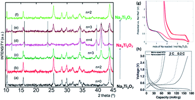 | ||
| Fig. 22 (a–f) In situ X-ray diffraction of a Na/Na2Ti3O7 cell cycled between 0.01 and 2.5 V at a C/50 rate. (g) Electrochemical profile of a (blue) blank electrode consisting of only carbon black (red) Na2Ti3O7 and 30 wt% carbon black218 (h) galvanostatic charge–discharge curves elucidating the size effect of micro- and nanosized Na2Ti3O7 tested at varying current densities of 0.2 and 2C, respectively.216 (a–f) Reprinted with permission from ref. 218. Copyright 2011 American Chemical Society. (h) Copyright 2013 Wiley-VCH Verlag GmbH & Co. KGaA, Weinheim. | ||
A low strain P2-Na0.66[Li0.22Ti0.78]O2 anode material was also proposed by Wang et al. Similar ionic-sized Li+ was used as a doping element for Ti, so as to increase the valence state of Ti3+ to Ti4+, thus stabilizing the TiO6 octahedra in the previously reported low-voltage layered Na2/3TiO2.85 P2-Na0.66[Li0.22Ti0.78]O2 possesses a P2-layered structure, isostructural to that of P2-Na2/3CoO2. The AA-type oxygen stacking provides a large interlayer (5.5636 Å) along the (002) plane. The galvanostatic profile (Fig. 23a) shows a quasi-solid-solution like reaction, giving rise to a reversible capacity of 116 mA h g−1 when cycled between 0.4 and 2.5 V vs. Na+/Na. An incredible cyclability was observed after 1200 cycles, with a small capacity decay of only 0.02% over each cycle (Fig. 23b). The coulombic attraction between Na ions and the interlayers reduces the interplanar distance during intercalation, while the reduction of the transition metal gives rise to an increase in transition metal-oxygen bonding. Li deinsertion was explained to be not possible due to the presence of a narrow Li+ migration path, while the migration of Li to Na sites was also found to be difficult when using density functional theory (DFT) calculations (Fig. 23c and d).219
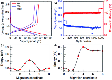 | ||
| Fig. 23 (a) The 1st, 50th, and 200th galvanostatic charge–discharge profiles of P2-Na0.66[Li0.22Ti0.78]O2 within a voltage range (b) cycling performance over 1200 cycles at 2C rate. DFT calculations for the migration energy barrier of a single vacancy assisted (c) Na+ diffusion in the Na layer, and (d) Li+ diffusion from the transition metal layer to the Na layer in P2Na0.66[Li0.22Ti0.78]O2 (ref. 219) reprinted with permission from Macmillan Publishers Ltd.: (Nat. Commun.) (ref. 219), copyright 2013. | ||
A large number of metal oxides and sulfides have been reported to be capable of delivering high capacity during lithium insertion via the conversion reaction: MaOb + 2bLi ↔ aM + bLi2O, (where, M = transition metal).8 Similar conversion mechanisms to form the elemental metal have also been proposed for many other oxides that electrochemically react with sodium. The first metal oxide reported as a conversion-type anode for NIBs was NiCo2O4 by Alcántara et al., as shown in Fig. 24a.220 Through a conversion reaction of NiCo2O4 to form Ni, Co and Na2O, although not completely confirmed in the report, a theoretical capacity of 890 mA h g−1 should be expected. However, the experimental results recorded a capacity of only ∼618/∼200 mA h g−1 for the initial discharge/charge process. Iron-based oxides, such as Fe2O3 (ref. 221–224) and Fe3O4,225 have also been reported to deliver significant sodium storage capacity via conversion reactions. Hariharan et al. reported an initial discharge/charge capacity of 643/366 mA h g−1 for Fe3O4.226 Selected area electron diffraction (SAED) patterns confirmed the formation of Fe and Na2O after discharge to 0.04 V vs. Na+/Na. Upon a further charge to 3.0 V, Fe3O4 was found on the SAED patterns, along with Fe and Na2O, suggesting poor reversibility in the conversion mechanism. The same group also reported α-MoO3 to have an initial discharge/charge capacity of 771 and 410 mA h g−1via a conversion reaction.227 Yuan et al. reported that CuO had a high initial discharge/charge capacity of ∼935/640 mA h g−1 (Fig. 24b). The CuO nanorod arrays were prepared by engraving copper foils, which ensured good contact between the active material and the current collector. However, a much lower capacity of <400 mA h g−1 was recorded for CuO electrodes prepared via a normal technique using PVDF as a binder, suggesting the importance of the electrode preparation in the utilization of active materials.228 When the metal element in an oxide is able to electrochemically alloy with sodium, an alloying reaction will further occur after the formation of the elemental metal via a conversion reaction, and this thus offers a very large capacity. These materials include Sb2O4,229 SnO,230,231 and SnO2.232–235 Sb2O4 has been reported to exhibit a very high capacity of ∼1000 mA h g−1. Other metal oxides reported to have a conversion reaction with sodium and to show a significant capacity include Co3O4,236,237 NiO,238 Mn3O4,222 and FeWO4.236
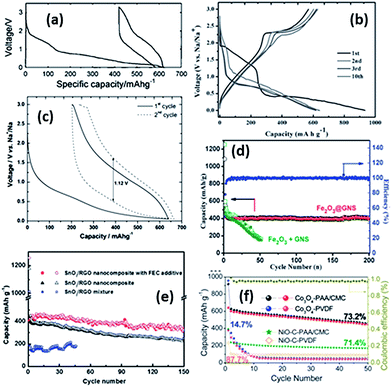 | ||
| Fig. 24 Discharge/charge curves of (a) NiCo2O4 at a 0.1C rate;220 (b) a CuO nanorod array at a current density of 20 mA g−1;228 and (c) a nanostructured Fe2O3 at a current density of 40 mA g−1.223 (d) Cycling performance of Fe2O3/GNS (mixture) and Fe2O3@GNS at a current of 100 mA g−1, and coulombic efficiency of the Fe2O3@GNS sample. GNS: graphene nanosheets;224 (e) a SnO2–RGO (reduced graphene oxide) nanocomposite and a mixture in 1 M NaClO4 in EC–PC with and without FEC additive at a current density of 100 mA h g−1;232 and (f) Co3O4 and NiO–C using different kinds of binders at a current density of 50 mA g−1. Polyacrylic acid (PAA), carboxymethyl cellulose (CMC), polyvinylidene fluoride (PVDF).238 (a) Reprinted with permission from ref. 220. Copyright 2002 American Chemical Society. (b) Copyright 2014 Wiley-VCH Verlag GmbH & Co. KGaA, Weinheim (c) reprinted with permission from ref. 223. Copyright 2014 Elsevier (d) reproduced from ref. 224 with permission from The Royal Society of Chemistry (e) reproduced from ref. 232 with permission from The Royal Society of Chemistry (f) reproduced from ref. 238 with permission from The Royal Society of Chemistry. | ||
Nonetheless, several obstacles for such conversion-type oxides in sodium storage still persist. For example, large potential hysteresis, low initial coulombic efficiency (most in the range of 30–70%) and poor cyclability. Furthermore, the potential difference during discharge and charge are usually large, and could be even larger than 1 V. Some examples are shown in Fig. 24a–c. The large hysteresis results in a very low round-trip efficiency, and is one of the main disadvantages of these materials. Fundamental knowledge about the origins of the hysteresis is quite limited, even in lithium storage applications. Several lithium storage studies have indicated that the hysteresis may have arisen from the different paths of the insertion/deinsertion reactions, the interfacial thermodynamics or even due to the mobility of the species during phase transformation.8 These might be helpful for understanding hysteresis in their sodium storage applications. Very few conversion oxides have exhibit an initial coulombic efficiency of greater than 80%, with some materials even showing efficiencies of only ∼30%. The low coulombic efficiency is related to the reversibility of the conversion reactions, as well as to the formation of the SEI layers. The reversibility of sodium insertion is usually worse than lithium insertion. This is usually attributed to the kinetic problems of the insertion/deinsertion reactions associated with the larger sodium ion, although this not quite fully understood.13,35 The formation of SEI layers is also partially responsible for the low efficiency. One possible solution to this is to reduce the surface area of the materials. The conversion-type materials are not capable of long-term cycling without any modification. The poor cyclability could be, at least partially, due to the instability of the electrodes caused by the large volume change during sodiation/desodiation. By proper material/electrode design, such as carbon coating and using core–shell structures, the cyclability could be significantly improved.232–234 Some examples are shown in Fig. 24d–f. In addition, modification of the electrolytes, such as by the addition of FEC to form more stable SEI layers, has also been reported to be beneficial for the cyclability (Fig. 24e).232
3.4. Sulfides
Many metal sulfides can also electrochemically react with sodium based on a conversion reaction to form the metal and sodium sulfides. If the metal can electrochemically alloy with sodium, such as tin and antimony, the conversion reaction will follow by an alloying reaction. These conversion-type sulfides include Ni3S2,239 MoS2,208,240–242 SnS2,243–245 SnS,243,246 Co9S8,247 Fe2S (ref. 248) and Sb2S3.176 For some of these materials, it has been reported that the de-conversion reaction is unable to form the original metal sulfides. For example, Shadike et al. proposed that, after the first conversion reaction of FeS2 to form Fe and Na2S, the following charge/discharge reactions proceeded according to the mechanism: Fe + Na2S ↔ NaxFeS2 + (4 − x) Na+ + (4 − x)e−.248 Similar to oxides based on the conversion reaction, these sulfides usually suffer from large hysteresis, low initial C.E. and poor cyclability. Lately, improvements in cycling performance have been made by using carbon composite materials and by modification of the electrolytes, such as with the addition of FEC. For example, Zhu et al. reported ultrasmall nanoplates of MoS2 embedded in carbon nanofibers with a rather stable cyclability (Fig. 25).240 Zhou et al. reported a SnS/graphene composite with no significant fading after 250 cycles by the addition of FEC in the electrolyte.243 Yu et al. also reported a Sb2S3/reduced graphene oxide composite with excellent cycling performance with the presence of FEC in the electrolyte.176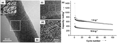 | ||
| Fig. 25 (a) TEM, and (b)–(d) HRTEM images of a MoS2 embedded in the carbon nanofiber; (e) cycling performance of the MoS2/carbon composite.240 Copyright 2014 Wiley-VCH Verlag GmbH & Co. KGaA, Weinheim. | ||
3.5. Phosphorus and phosphides
Recently, phosphorus has been found to have the highest capacity among all the anodes for NIBs.249,250 Based on the reaction: P + 3Na ↔ Na3P, this material has a theoretical capacity of 2596 mA h g−1. Also, a reversible capacity of up to 1800–1900 mA h g−1 has been achieved. In addition, most of the capacity is delivered below 0.8 V vs. Na+/Na (Fig. 26a), and thus it holds promise for the construction of high voltage NIBs. The reported initial coulombic efficiency could be as high as 87%, and could even reach 99% for the third cycle. Although this may still not high enough for practical application, this initial efficiency is among the highest of all the sodium anode materials reported to date. These features make phosphorus very promising as an anode for high energy density NIBs. The disadvantages of this material similarly includes the poor cycling performance, which could be mainly due to the large volume change (308%) induced by uptake/extraction of the large amount of sodium. Modification of the interface between the electrode and electrolyte, such as by using an FEC additive, may also benefit the cycling performance.250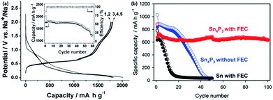 | ||
| Fig. 26 (a) Charge/discharge curves of an amorphous phosphorus at a current density of 250 mA g−1; inset shows the cycling performance.250 (b) Comparison of the cycling performance of Sn4P3 and Sn, with and without FEC.251 (a) Copyright 2013 Wiley-VCH Verlag GmbH & Co. KGaA, Weinheim. (b) Copyright 2014 Wiley-VCH Verlag GmbH & Co. KGaA, Weinheim. | ||
Sn4P3 has also been reported to reversibly provide a capacity of higher than 800 mA h g−1. Most of the capacity was observed to be delivered at a low potential window, <1.0 V vs. Na+/Na. It is interesting that the studies carried out by different groups showed different processes for the sodiation/desodiation of this material.225,251,252 Kim et al. reported the formation of amorphous NaxP and nanocrystalline Na15Sn4 after discharging to 0.01 V vs. Na+/Na. The subsequent charging process resulted in a gradual re-formation of Sn4P3, as monitored by XRD.251 However, while the formation of Na15Sn4 was confirmed after sodiation by Qian et al., they only found amorphous products during the subsequent desodiation.252 Further studies are needed to understand the mechanisms involved. This material also has a disadvantage of a large volume change during discharge/charge, and thus a poor cycling performance without modifications being carried out (Fig. 26b). Additionally another phosphide, NiP3, was also reported as an anode for NIBs, as it has a reversible capacity of larger than 1000 mA h g−1.253
3.6. Organic compounds
Similarly, organic compounds have also been studied as prospective anode materials in NIBs. They bring higher structure flexibility and a cheaper cost, as well as an open structure for better structure kinetics. The use of disodium terephthalate (Na2C8H4O4) was first demonstrated by Zhao et al.254 The anode was prepared via a ball milling method with commercially available Na2C8H4O4 and Ketjen black. The galvanostatic profile showed a flat-discharge plateau at 0.29 V vs. Na+/Na, with a reversible capacity of 250 mA h g−1. It was also reported that by providing an Al2O3 coating on the surface of Na2C8H4O4, the electrochemical storage and cycling performance could be improved. Park et al. also prepared Na2C8H4O4 using a facile wet chemistry method, as shown in Fig. 27a. When tested within a potential window from 0.0–2.0 V vs. Na+/Na, an initial capacity of approximately 500 mA h g−1 was obtained, which subsequently dropped to 300 mA h g−1 (Fig. 27b). An ideal intercalation potential of 0.29 V was also observed from the 2nd cycle onwards. This not only prevents the formation of dendrites, but could also provide for a high energy density when assembled in a full cell. The mechanism for the charge storage is via the stabilized conjugated structure between the carbonyl and phenyl groups. However, it worth noting that a high percentage of Super P (37.5%) was used, due to the insulative nature of the organic compounds.255 Abouimrane probed into several sodium-based carboxylate molecules, as well as 3.6 V sodium-based full cells that could operate at room temperature. Nonetheless, the 1st cycle efficiency has to be improved before commercialization could be considered.256 Novel polymeric Schiff bases were also reported to be active for sodium storage. These compounds consist of two redox active Schiff base groups (–N![[double bond, length as m-dash]](https://www.rsc.org/images/entities/char_e001.gif) CH–Ar-HC
CH–Ar-HC![[double bond, length as m-dash]](https://www.rsc.org/images/entities/char_e001.gif) N–), and they were synthesized from a one-step polycondensation method between non-conjugated aliphatic/conjugated aromatic diamine blocks with a terephthalaldehyde unit. NaFSI in methyltetrahydrofuran (Me-THF) was employed as the electrolyte and a maximum capacity of 350 mA h g−1 could be achieved at a rate of C/10.257 4,4′-Biphenyldicarboxylate (BPDC) sodium coordinated compounds of different crystal structures were studied by Choi et al. A full discharge yields a capacity of about 200 mA h g−1, with a voltage plateau at 0.5 V vs. Na+/Na. However, despite the high cycling stability and rate performance, the amount of conductive additive added was still very high (∼28.6%), which is undesirable in practical devices.140
N–), and they were synthesized from a one-step polycondensation method between non-conjugated aliphatic/conjugated aromatic diamine blocks with a terephthalaldehyde unit. NaFSI in methyltetrahydrofuran (Me-THF) was employed as the electrolyte and a maximum capacity of 350 mA h g−1 could be achieved at a rate of C/10.257 4,4′-Biphenyldicarboxylate (BPDC) sodium coordinated compounds of different crystal structures were studied by Choi et al. A full discharge yields a capacity of about 200 mA h g−1, with a voltage plateau at 0.5 V vs. Na+/Na. However, despite the high cycling stability and rate performance, the amount of conductive additive added was still very high (∼28.6%), which is undesirable in practical devices.140
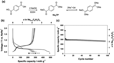 | ||
| Fig. 27 (a) Schematic of the synthesis of sodium terephthalate as an organic anode material, as well as the reversible Na insertion/deinsertion mechanism. (b) Electrochemical charge–discharge voltage profile of sodium terephthalate at different cycles@30 mA g−1 (c) cycling performance of sodium terephthalate@30 mA g−1 (ref. 255). Copyright 2012 Wiley-VCH Verlag GmbH & Co. KGaA, Weinheim. | ||
4. Summary and perspectives
The development of energy storage devices has been ongoing for over 200 years. However, the performance of such devices constantly falls back on the increasing expectations and demands of the consumers. Reliability and safety are key factors that primarily determine the commercialization of batteries. As demand continues to rise, controversial debates have arisen in today's context on the limited availability of lithium reserves, which has encouraged researchers to investigate more appealing alternatives such as sodium. The key motivation for research on room-temperature sodium-based systems ultimately falls on the lower cost per unit energy that the device can provide. However, such technology is not new and review articles could be found even from the early 1980s. Nevertheless, despite the similar chemical properties of Li and Na, the performance of sodium-based devices described in this review requires further improvement and is still far from commercialization requirements.A wide variety of potential cathode materials, including layered oxides (NaMO2, where M = Fe, Ni, Co, Mn and etc.); phosphates (NaMPO4, where M = Fe, Co, Ni, Mn and etc.); pyrophosphates (Na2MP2O7, where M = Fe, Mn and Co); NASICON-based fluorophosphates (Na3V2PO4F); organic compounds and sulphates have been covered in this review. In general, sodium cathodes with a similar structure to their lithium analogues have shown lower operating potentials compared to their lithium counterparts, indicating the reduction of energy density. As was mentioned by Tarascon, the energy density in rechargeable batteries has been largely limited to date by the performance of the cathode material, in which doubling the cathode's specific capacity would lead to a 57% increment in energy density.258
Several ways to improve cathode performance have already been demonstrated, including having multiple active redox couples within a simple compound and the tailoring of the polyanionic group (in phosphates and sulfates). Partial substitution of metal oxides (e.g. P2-, O3-NaxFe1/3Mn2/3O2, NaFe1/3Mn1/2Ti1/6O2, NaFe1/2Co1/2, NaNi1/2Mn1/2O2) has been observed to be a popular trend in resolving problems, compared to their primary form. For example, the issue of iron migration at high voltages in P2-NaFeO2 and the poor reversibility in P2-NaxFe1/3Mn2/3O2 during cycling was effectively suppressed in NaFe1/3Mn1/2Ti1/6O2 due to the synergistic effects from partial substitution of Mn and Ti, respectively. Furthermore, despite Na and Li having similar properties, similar crystal analogues in respective systems have shown contrasting performances. It is well elaborated that the periodic arrangement of the atoms/molecules are responsible for the nature of sodium-ion storage within the structure of the material. As shown in NaCoO2, the larger interslab distances provide a reduced diffusion energy barrier compared to its lithium counterpart, which could help overcome the sluggish kinetics of the larger-sized Na ions. One other example would be NaCrO2vs. LiCrO2, where the former is more electrochemically active compared to the latter. Other cathodic compounds, such as MnO2, V2O5 and FeF3, have shown promising electrochemical performances; however, full cell practically is largely limited due to the additional pre-sodiation step required. Their pre-sodiated compounds, i.e. Na0.44MnO2, NaV6O15, NaV3O8, NaFeF3, despite having a lower specific capacity, are more practical, when it comes to commercialization.
Additionally, the sodium storage mechanism and capability depends to a large extent on the crystal structure of the material. Ab initio calculations with a fundamental understanding of the crystal structure should provide interesting guidelines to understanding and designing more efficient electrodes and batteries. Comparisons between amorphous and crystalline materials might prove to be an interesting area, considering that amorphous V2O5 was able to outperform nanocrystlline V2O5. However, the charge storage mechanism of such amorphous materials is still vague and is leaning more towards a pseudocapacitive behaviour instead.
Comparatively, polyanionic materials appear to be a much better choice, as they benefit from the inductive effect from the PO43− group, which raises the intercalation redox potential and also the energy density of the system. Similar inductive effects were also observed in sulfate-based compounds, suggesting room for tailoring the redox potential in order to maximize the overall energy density. Novel compounds, including fluorophosphates, pryophosphates and co-pyrophosphate–polyanionic compounds, have also been explored; however, their use is limited by the low capacity they provide. Different synthesis techniques could also be explored in order to improve the electrochemical performance of the material via rational design. For instance, Na2FePO4F/C hollow particles prepared from spray pyrolysis were able to cycle for a longer period compared to Na2FePO4F/C prepared via a solid-state synthesis. New directions should be looked into for developing stable and high potential redox couple materials in order to narrow the gap between LIBs and NIBs. Nonetheless, fundamental questions regarding differences in the thermodynamic and electrochemical properties of Na analogues as opposed to Li-based structures have yet to be answered. Organic compounds (e.g. Na4DHTPA, PTCDA) and sulphates (Na2Fe2(SO4)3) have proven to be greener alternatives, due to the use of cheaper and more abundant biomass elements.259 In the organic compounds category, despite the high specific capacity they are able to provide, the operating potential of such materials remain too low (∼1.7 to 1.9 V vs. Na+/Na). By tuning the different electron withdrawing aromatic groups in the polyimides, the overall energy level of the compounds can be varied. Further improvements to develop better materials will heavily rely on an intersection of knowledge between the fields of organic chemistry and electrochemistry.
As for anode materials, carbonaceous materials appear to be the most cost-effective candidates, although they possess relatively low capacity. Their cyclability has been significantly improved over the past years; however, challenges still remain with these materials, especially in terms of the low initial coulombic efficiency. Additionally, the low voltage plateau (∼0.1 V) is a safety concern for sodium plating, especially when subjected to tests under high current rates. Other oxides undergoing conversion reactions, e.g. CuO, and materials undergoing alloying reactions, e.g. Sn, Sb, Pb and Ge, have shown very high specific capacity, but are unsuitable for long-term cycling operations, due to their large volume change during sodiation and desodiation processes. The recent development in sulfides, organic compounds, and phosphorus-based materials also provides the possibility for use in high-capacity anodes. Nonetheless, all of these materials suffer from a relatively low initial coulombic efficiency and/or poor cyclability. We believe that a tailored design to suit the large volume expansion is necessary to meet the shortcomings of these materials. In addition, for oxides and sulfides based on conversion reactions, a large potential hysteresis is one of their main drawbacks. A fundamental understanding on the low reversibility and the formation of SEI layers, which together result in the low coulombic efficiency, and on the large hysteresis is significantly lacking, and is essential for future commercialization. Very few of the anode materials that have been investigated so far have shown initial C.E. that are >80%. For practical application, probably >90% is needed according to commercial LIB anode standards. Interestingly, P2-Na0.66[Li0.22Ti0.78]O2 showed an excellent performance in terms of rate capability and cycling life, owing to the quasi-single phase transformation and minimal volume change during cycling. Such a zero-strain material is also seen in spinel Li4Ti5O12 that is used as an anode in LIBs and could be exploited for the further development of electrodes in NIBs. These parameters are crucial for the development and commercialization of cheap, large-scale efficient energy storage devices.
Mixed transition metal oxides (MTMO) (designated as AxB3−xO4, where A, B = Co, Ni, Fe, etc.) have received a tremendous amount of success as anodes in LIB technology, but up until now, only NiCo2O4 has been reported. We believe that an in-depth understanding, in terms of the conversion process of these oxides in sodium-based systems, is necessary.
Although the chemistry of electrolytes was not covered in detail in this review, optimization of the salts and solvents for several examples were briefly discussed. While the use of NaClO4 salt is widespread, other salts, such as NaFSI, NaBF4, NaPF6,have been explored as well. The electrochemical performance of NaFSI appears to be promising, but further work has to be done to understand the mechanism for improvement. To improve their cyclability, advanced material/electrode design and modification of the interface between the electrode and electrolyte are required. Different passivation chemistries at the interface compared to LIBs, could also be another factor resulting in the low coulombic efficiency of the electrode materials. The addition of FEC additives has found immense success in stabilizing the passivation layer, and has resulted in improved cyclability and electrochemical performances. However, despite the success, the high cost of such additives is counter-objective for when developing cheap alternative sodium-based electrochemical energy storage. Therefore, one must look for other alternatives/additives to improve the cycling and electrochemical performance in the overall system. Nonetheless, this is easier said than done.
All in all, the progress of sodium-based electrochemical devices is still in its infancy. The end application of such technology has not been clearly defined yet. However, we can be sure that this technology will be employed in applications where weight is of no concern. One such example could be for large-scale grid energy storage, where the source of energy comes from intermittent sources such as wind, tidal and solar. Much work has to be done to improve the performance matrix of such systems, mainly in energy and power density, cyclability, thermal stability, coulombic efficiency, cost, etc. Most of these issues could be addressed with better design of materials, e.g. carbon coating, nanosizing, doping and etc., while using only earth abundant resources as precursors for materials. We are confident that the development of low cost, large-scale and long-lasting sodium-based electrochemical devices would be an interesting route and that they will be able to compete with lithium-based systems in the long run, especially in the fields where both high performance and low-cost storage systems are required.
Acknowledgements
This work is supported by Tier 1 grants of Singapore Ministry of Education (RGT8/13, RG131/14, & RG13/13) and the Singapore National Research Foundation under its Campus for Research Excellence And Technological Enterprise (CREATE) programme.Notes and references
- J.-M. Tarascon and M. Armand, Nature, 2001, 414, 359–367 CrossRef CAS PubMed.
- A. S. Arico, P. Bruce, B. Scrosati, J.-M. Tarascon and W. van Schalkwijk, Nat. Mater., 2005, 4, 366–377 CrossRef CAS PubMed.
- C. Liu, F. Li, L.-P. Ma and H.-M. Cheng, Adv. Mater., 2010, 22, E28–E62 CrossRef CAS PubMed.
- W. H. Meyer, Adv. Mater., 1998, 10, 439–448 CrossRef CAS.
- Y. Sun, Q. Wu and G. Shi, Energy Environ. Sci., 2011, 4, 1113–1132 CAS.
- H. Li, Z. Wang, L. Chen and X. Huang, Adv. Mater., 2009, 21, 4593–4607 CrossRef CAS.
- V. Etacheri, R. Marom, R. Elazari, G. Salitra and D. Aurbach, Energy Environ. Sci., 2011, 4, 3243–3262 CAS.
- J. Cabana, L. Monconduit, D. Larcher and M. Rosa Palacin, Adv. Mater., 2010, 22, E170–E192 CrossRef CAS PubMed.
- J. W. Fergus, J. Power Sources, 2010, 195, 939–954 CrossRef CAS PubMed.
- S. Flandrois and B. Simon, Carbon, 1999, 37, 165–180 CrossRef CAS.
- L. Ji, Z. Lin, M. Alcoutlabi and X. Zhang, Energy Environ. Sci., 2011, 4, 2682–2699 CAS.
- L. P. Wang, L. Yu, R. Satish, J. Zhu, Q. Yan, M. Srinivasan and Z. Xu, RSC Adv., 2014, 4, 37389–37394 RSC.
- S.-W. Kim, D.-H. Seo, X. Ma, G. Ceder and K. Kang, Adv. Energy Mater., 2012, 2, 710–721 CrossRef CAS.
- M. D. Slater, D. Kim, E. Lee and C. S. Johnson, Adv. Funct. Mater., 2013, 23, 947–958 CrossRef CAS.
- V. Palomares, P. Serras, I. Villaluenga, K. B. Hueso, J. Carretero-Gonzalez and T. Rojo, Energy Environ. Sci., 2012, 5, 5884–5901 CAS.
- T. L. Site, http://www.lithiumsite.com/market.html, August 2014.
- S. Y. Hong, Y. Kim, Y. Park, A. Choi, N.-S. Choi and K. T. Lee, Energy Environ. Sci., 2013, 6, 2067–2081 CAS.
- K. B. Hueso, M. Armand and T. Rojo, Energy Environ. Sci., 2013, 6, 734–749 CAS.
- B. L. Ellis and L. F. Nazar, Curr. Opin. Solid State Mater. Sci., 2012, 16, 168–177 CrossRef CAS PubMed.
- C.-X. Zu and H. Li, Energy Environ. Sci., 2011, 4, 2614–2624 CAS.
- T. Nagaura and K. Tozawa, Prog. Batteries Sol. Cells, 1990, 9, 209–213 CAS.
- Y. Nishi, Chem. Rec., 2001, 1, 406–413 CrossRef CAS PubMed.
- S. P. Ong, V. L. Chevrier, G. Hautier, A. Jain, C. Moore, S. Kim, X. Ma and G. Ceder, Energy Environ. Sci., 2011, 4, 3680–3688 CAS.
- H. Huang, S. C. Yin, T. Kerr, N. Taylor and L. F. Nazar, Adv. Mater., 2002, 14, 1525–1528 CrossRef CAS.
- M. M. Ren, Z. Zhou, X. P. Gao, W. X. Peng and J. P. Wei, J. Phys. Chem. C, 2008, 112, 5689–5693 CAS.
- W. Song, X. Ji, Z. Wu, Y. Zhu, Y. Yao, K. Huangfu, Q. Chen and C. E. Banks, J. Mater. Chem. A, 2014, 2, 2571–2577 CAS.
- W. Song, X. Ji, Y. Yao, H. Zhu, Q. Chen, Q. Sun and C. E. Banks, Phys. Chem. Chem. Phys., 2014, 16, 3055–3061 RSC.
- B. L. Ellis, T. N. Ramesh, W. N. Rowan-Weetaluktuk, D. H. Ryan and L. F. Nazar, J. Mater. Chem., 2012, 22, 4759–4766 RSC.
- H. Kim, I. Park, D.-H. Seo, S. Lee, S.-W. Kim, W. J. Kwon, Y.-U. Park, C. S. Kim, S. Jeon and K. Kang, J. Am. Chem. Soc., 2012, 134, 10369–10372 CrossRef CAS PubMed.
- N. R. Khasanova, O. A. Drozhzhin, D. A. Storozhilova, C. Delmas and E. V. Antipov, Chem. Mater., 2012, 24, 4271–4273 CrossRef CAS.
- S. Y. Hong, Y. Kim, Y. Park, A. Choi, N. S. Choi and K. T. Lee, Energy Environ. Sci., 2013, 6, 2067–2081 CAS.
- K. Kubota, N. Yabuuchi, H. Yoshida, M. Dahbi and S. Komaba, MRS Bull., 2014, 39, 416–422 CrossRef CAS.
- M. H. Han, E. Gonzalo, G. Singh and T. Rojo, Energy Environ. Sci., 2015, 8, 81–102 CAS.
- M. Dahbi, N. Yabuuchi, K. Kubota, K. Tokiwa and S. Komaba, Phys. Chem. Chem. Phys., 2014, 16, 15007–15028 RSC.
- V. Palomares, M. Casas-Cabanas, E. Castillo-Martinez, M. H. Han and T. Rojo, Energy Environ. Sci., 2013, 6, 2312–2337 CAS.
- A. Ponrouch, D. Monti, A. Boschin, B. Steen, P. Johansson and M. R. Palacin, J. Mater. Chem. A, 2015, 3, 22–42 CAS.
- N. Yabuuchi, K. Kubota, M. Dahbi and S. Komaba, Chem. Rev., 2014, 114, 11636–11682 CrossRef CAS PubMed.
- Y. Kim, K.-H. Ha, S. M. Oh and K. T. Lee, Chem.–Eur. J., 2014, 20, 11980–11992 CrossRef CAS PubMed.
- H. Pan, Y.-S. Hu and L. Chen, Energy Environ. Sci., 2013, 6, 2338–2360 CAS.
- M. S. Islam and C. A. J. Fisher, Chem. Soc. Rev., 2014, 43, 185–204 RSC.
- C. F. Delmas and P. Hagenmuller, Physica B+C, 1980, 99, 81–85 CrossRef CAS.
- J.-J. Braconnier, C. Delmas, C. Fouassier and P. Hagenmuller, Mater. Res. Bull., 1980, 15, 1797–1804 CrossRef CAS.
- C. Fouassier, G. Matejka, J.-M. Reau and P. Hagenmuller, J. Solid State Chem., 1973, 6, 532–537 CrossRef CAS.
- G. J. Shu and F. C. Chou, Phys. Rev. B: Condens. Matter Mater. Phys., 2008, 78, 052101 CrossRef.
- Q. Huang, M. L. Foo, R. A. Pascal, J. W. Lynn, B. H. Toby, T. He, H. W. Zandbergen and R. J. Cava, Phys. Rev. B: Condens. Matter Mater. Phys., 2004, 70, 184110 CrossRef.
- J. B. Goodenough and Y. Kim, Chem. Mater., 2009, 22, 587–603 CrossRef.
- B. L. Ellis, K. T. Lee and L. F. Nazar, Chem. Mater., 2010, 22, 691–714 CrossRef CAS.
- C. Delmas, J.-J. Braconnier, C. Fouassier and P. Hagenmuller, Solid State Ionics, 1981, 3–4, 165–169 CrossRef CAS.
- J. Molenda, C. Delmas and P. Hagenmuller, Solid State Ionics, 1983, 9–10, 431–435 CrossRef CAS.
- T. Shibata, W. Kobayashi and Y. Moritomo, Appl. Phys. Express, 2013, 6, 097101 CrossRef.
- H. Xia, L. Lu and G. Ceder, J. Power Sources, 2006, 159, 1422–1427 CrossRef CAS PubMed.
- J.-H. Cheng, C.-J. Pan, J.-F. Lee, J.-M. Chen, M. Guignard, C. Delmas, D. Carlier and B.-J. Hwang, Chem. Mater., 2013, 26, 1219–1225 CrossRef.
- D. Carlier, J. H. Cheng, R. Berthelot, M. Guignard, M. Yoncheva, R. Stoyanova, B. J. Hwang and C. Delmas, Dalton Trans., 2011, 40, 9306–9312 RSC.
- H. Yoshida, N. Yabuuchi and S. Komaba, Electrochem. Commun., 2013, 34, 60–63 CrossRef CAS PubMed.
- N. Yabuuchi, M. Kajiyama, J. Iwatate, H. Nishikawa, S. Hitomi, R. Okuyama, R. Usui, Y. Yamada and S. Komaba, Nat. Mater., 2012, 11, 512–517 CrossRef CAS PubMed.
- N. Yabuuchi, H. Yoshida and S. Komaba, Electrochemistry, 2012, 80, 716–719 CrossRef CAS PubMed.
- S. Kim, X. Ma, S. P. Ong and G. Ceder, Phys. Chem. Chem. Phys., 2012, 14, 15571–15578 RSC.
- H. Yoshida, N. Yabuuchi, K. Kubota, I. Ikeuchi, A. Garsuch, M. Schulz-Dobrick and S. Komaba, Chem. Commun., 2014, 50, 3677–3680 RSC.
- M. H. Han, E. Gonzalo, M. Casas-Cabanas and T. Rojo, J. Power Sources, 2014, 258, 266–271 CrossRef CAS PubMed.
- P. Vassilaras, X. Ma, X. Li and G. Ceder, J. Electrochem. Soc., 2013, 160, A207–A211 CrossRef CAS PubMed.
- I. Hasa, D. Buchholz, S. Passerini, B. Scrosati and J. Hassoun, Adv. Energy Mater., 2014, 4, 1400083 Search PubMed.
- D. Kim, E. Lee, M. Slater, W. Lu, S. Rood and C. S. Johnson, Electrochem. Commun., 2012, 18, 66–69 CrossRef CAS PubMed.
- X. Li, D. Wu, Y.-N. Zhou, L. Liu, X.-Q. Yang and G. Ceder, Electrochem. Commun., 2014, 49, 51–54 CrossRef CAS PubMed.
- H. Y.-S. Mu Lin-Qin and C. Li-Quan, Chin. Phys. B, 2015, 24, 38202–038202 CrossRef.
- S.-Y. Xu, X.-Y. Wu, Y.-M. Li, Y.-S. Hu and L.-Q. Chen, Chin. Phys. B, 2014, 23, 118202 CrossRef.
- Y. Ono, Y. Yui, M. Hayashi, K. Asakura, H. Kitabayashi and K. I. Takahashi, ECS Trans., 2014, 58, 33–39 CrossRef PubMed.
- S. Komaba, C. Takei, T. Nakayama, A. Ogata and N. Yabuuchi, Electrochem. Commun., 2010, 12, 355–358 CrossRef CAS PubMed.
- C.-Y. Chen, K. Matsumoto, T. Nohira, R. Hagiwara, A. Fukunaga, S. Sakai, K. Nitta and S. Inazawa, J. Power Sources, 2013, 237, 52–57 CrossRef CAS PubMed.
- S. Komaba, T. Nakayama, A. Ogata, T. Shimizu, C. Takei, S. Takada, A. Hokura and I. Nakai, ECS Trans., 2009, 16, 43–55 CAS.
- J.-J. Ding, Y.-N. Zhou, Q. Sun and Z.-W. Fu, Electrochem. Commun., 2012, 22, 85–88 CrossRef CAS PubMed.
- D. A. Tompsett and M. S. Islam, Chem. Mater., 2013, 25, 2515–2526 CrossRef CAS.
- D. Su, H.-J. Ahn and G. Wang, J. Mater. Chem. A, 2013, 1, 4845–4850 CAS.
- J. M. Tarascon, D. G. Guyomard, B. Wilkens, W. R. Mc Kinnon and P. Barboux, Solid State Ionics, 1992, 57, 113–120 CrossRef CAS.
- F. Sauvage, L. Laffont, J. M. Tarascon and E. Baudrin, Inorg. Chem., 2007, 46, 3289–3294 CrossRef CAS PubMed.
- H. Kim, D. J. Kim, D.-H. Seo, M. S. Yeom, K. Kang, D. K. Kim and Y. Jung, Chem. Mater., 2012, 24, 1205–1211 CrossRef CAS.
- Y. Cao, L. Xiao, W. Wang, D. Choi, Z. Nie, J. Yu, L. V. Saraf, Z. Yang and J. Liu, Adv. Mater., 2011, 23, 3155–3160 CrossRef CAS PubMed.
- L. Su, J. Winnick and P. Kohl, J. Power Sources, 2001, 101, 226–230 CrossRef CAS.
- P. E. Tang, J. S. Sakamoto, E. Baudrin and B. Dunn, J. Non-Cryst. Solids, 2004, 350, 67–72 CrossRef CAS PubMed.
- J.-C. Badot and N. Baffier, J. Mater. Chem., 1992, 2, 1167–1174 RSC.
- S. Tepavcevic, H. Xiong, V. R. Stamenkovic, X. Zuo, M. Balasubramanian, V. B. Prakapenka, C. S. Johnson and T. Rajh, ACS Nano, 2011, 6, 530–538 CrossRef PubMed.
- D. Su and G. Wang, ACS Nano, 2013, 7, 11218–11226 CrossRef CAS PubMed.
- D. W. Su, S. X. Dou and G. X. Wang, J. Mater. Chem. A, 2014, 2, 11185–11194 CAS.
- V. Raju, J. Rains, C. Gates, W. Luo, X. Wang, W. F. Stickle, G. D. Stucky and X. Ji, Nano Lett., 2014, 14, 4119–4124 CrossRef CAS PubMed.
- E. Uchaker, Y. Z. Zheng, S. Li, S. L. Candelaria, S. Hu and G. Z. Cao, J. Mater. Chem. A, 2014, 2, 18208–18214 CAS.
- A. Maazaz, C. Delmas and P. Hagenmuller, J. Inclusion Phenom., 1983, 1, 45–51 CrossRef CAS.
- C. Didier, M. Guignard, C. Denage, O. Szajwaj, S. Ito, I. Saadoune, J. Darriet and C. Delmas, Electrochem. Solid-State Lett., 2011, 14, A75–A78 CrossRef CAS PubMed.
- D. Hamani, M. Ati, J.-M. Tarascon and P. Rozier, Electrochem. Commun., 2011, 13, 938–941 CrossRef CAS PubMed.
- M. Guignard, C. Didier, J. Darriet, P. Bordet, E. Elkaïm and C. Delmas, Nat. Mater., 2013, 12, 74–80 CrossRef CAS PubMed.
- H. Wang, W. Wang, Y. Ren, K. Huang and S. Liu, J. Power Sources, 2012, 199, 263–269 CrossRef CAS PubMed.
- H. He, G. Jin, H. Wang, X. Huang, Z. Chen, D. Sun and Y. Tang, J. Mater. Chem. A, 2014, 2, 3563–3570 CAS.
- H. Wang, S. Liu, Y. Ren, W. Wang and A. Tang, Energy Environ. Sci., 2012, 5, 6173–6179 CAS.
- H. Liu, H. Zhou, L. Chen, Z. Tang and W. Yang, J. Power Sources, 2011, 196, 814–819 CrossRef CAS PubMed.
- H. He, X. Zeng, H. Wang, N. Chen, D. Sun, Y. Tang, X. Huang and Y. Pan, J. Electrochem. Soc., 2015, 162, A39–A43 CrossRef CAS PubMed.
- A. K. Padhi, K. S. Nanjundaswamy, C. Masquelier and J. B. Goodenough, J. Electrochem. Soc., 1997, 144, 2581–2586 CrossRef CAS PubMed.
- A. K. Padhi, K. S. Nanjundaswamy and J. B. Goodenough, J. Electrochem. Soc., 1997, 144, 1188–1194 CrossRef CAS PubMed.
- A. K. Padhi, K. S. Nanjundaswamy, C. Masquelier, S. Okada and J. B. Goodenough, J. Electrochem. Soc., 1997, 144, 1609–1613 CrossRef CAS PubMed.
- K. Zaghib, J. Trottier, P. Hovington, F. Brochu, A. Guerfi, A. Mauger and C. M. Julien, J. Power Sources, 2011, 196, 9612–9617 CrossRef CAS PubMed.
- P. Moreau, D. Guyomard, J. Gaubicher and F. Boucher, Chem. Mater., 2010, 22, 4126–4128 CrossRef CAS.
- M. Casas-Cabanas, V. V. Roddatis, D. Saurel, P. Kubiak, J. Carretero-Gonzalez, V. Palomares, P. Serras and T. Rojo, J. Mater. Chem., 2012, 22, 17421–17423 RSC.
- S.-M. Oh, S.-T. Myung, J. Hassoun, B. Scrosati and Y.-K. Sun, Electrochem. Commun., 2012, 22, 149–152 CrossRef CAS PubMed.
- B. L. Ellis, W. R. M. Makahnouk, Y. Makimura, K. Toghill and L. F. Nazar, Nat. Mater., 2007, 6, 749–753 CrossRef CAS PubMed.
- N. Recham, J.-N. Chotard, L. Dupont, K. Djellab, M. Armand and J.-M. Tarascon, J. Electrochem. Soc., 2009, 156, A993–A999 CrossRef CAS PubMed.
- A. Langrock, Y. Xu, Y. Liu, S. Ehrman, A. Manivannan and C. Wang, J. Power Sources, 2013, 223, 62–67 CrossRef CAS PubMed.
- J. Barker, M. Y. Saidi and J. L. Swoyer, Electrochem. Solid-State Lett., 2003, 6, A1–A4 CrossRef CAS PubMed.
- Y.-U. Park, D.-H. Seo, H.-S. Kwon, B. Kim, J. Kim, H. Kim, I. Kim, H.-I. Yoo and K. Kang, J. Am. Chem. Soc., 2013, 135, 13870–13878 CrossRef CAS PubMed.
- Y.-U. Park, D.-H. Seo, B. Kim, K.-P. Hong, H. Kim, S. Lee, R. A. Shakoor, K. Miyasaka, J.-M. Tarascon and K. Kang, Sci. Rep., 2012, 2, 704 Search PubMed.
- G. Li, D. Jiang, H. Wang, X. Lan, H. Zhong and Y. Jiang, J. Power Sources, 2014, 265, 325–334 CrossRef CAS PubMed.
- C. Delmas, A. Nadiri and J. L. Soubeyroux, Solid State Ionics, 1988, 28–30, 419–423 CrossRef.
- Z. Jian, L. Zhao, H. Pan, Y.-S. Hu, H. Li, W. Chen and L. Chen, Electrochem. Commun., 2012, 14, 86–89 CrossRef CAS PubMed.
- Z. Jian, W. Han, X. Lu, H. Yang, Y.-S. Hu, J. Zhou, Z. Zhou, J. Li, W. Chen, D. Chen and L. Chen, Adv. Energy Mater., 2013, 3, 156–160 CrossRef CAS.
- Z. Jian, C. Yuan, W. Han, X. Lu, L. Gu, X. Xi, Y.-S. Hu, H. Li, W. Chen, D. Chen, Y. Ikuhara and L. Chen, Adv. Funct. Mater., 2014, 24, 4265–4272 CrossRef CAS.
- H. Kim, I. Park, S. Lee, H. Kim, K.-Y. Park, Y.-U. Park, H. Kim, J. Kim, H.-D. Lim, W.-S. Yoon and K. Kang, Chem. Mater., 2013, 25, 3614–3622 CrossRef CAS.
- P. Barpanda, G. Rousse, T. Ye, C. D. Ling, Z. Mohamed, Y. Klein and A. Yamada, Inorg. Chem., 2013, 52, 3334–3341 CrossRef CAS PubMed.
- J. Du, L. Jiao, Q. Wu, Y. Liu, Y. Zhao, L. Guo, Y. Wang and H. Yuan, Electrochim. Acta, 2013, 103, 219–225 CrossRef CAS PubMed.
- P. Barpanda, T. Ye, S.-C. Chung, Y. Yamada, S.-i. Nishimura and A. Yamada, J. Mater. Chem., 2012, 22, 13455–13459 RSC.
- T. Ye, P. Barpanda, S.-i. Nishimura, N. Furuta, S.-C. Chung and A. Yamada, Chem. Mater., 2013, 25, 3623–3629 CrossRef CAS.
- P. Barpanda, T. Ye, S.-i. Nishimura, S.-C. Chung, Y. Yamada, M. Okubo, H. Zhou and A. Yamada, Electrochem. Commun., 2012, 24, 116–119 CrossRef CAS PubMed.
- P. Barpanda, T. Ye, M. Avdeev, S.-C. Chung and A. Yamada, J. Mater. Chem. A, 2013, 1, 4194–4197 CAS.
- P. Barpanda, J. Lu, T. Ye, M. Kajiyama, S.-C. Chung, N. Yabuuchi, S. Komaba and A. Yamada, RSC Adv., 2013, 3, 3857–3860 RSC.
- I. Hasa, J. Hassoun, Y.-K. Sun and B. Scrosati, ChemPhysChem, 2014, 15, 2152–2155 CrossRef CAS PubMed.
- K. Sakaushi, E. Hosono, G. Nickerl, T. Gemming, H. Zhou, S. Kaskel and J. Eckert, Nat. Commun., 2013, 4, 1485 CrossRef PubMed.
- S. Wang, L. Wang, Z. Zhu, Z. Hu, Q. Zhao and J. Chen, Angew. Chem., 2014, 126, 6002–6006 CrossRef.
- X. Wu, W. Deng, J. Qian, Y. Cao, X. Ai and H. Yang, J. Mater. Chem. A, 2013, 1, 10130–10134 CAS.
- C. D. Wessells, R. A. Huggins and Y. Cui, Nat. Commun., 2011, 2, 550 CrossRef PubMed.
- H. Lee, Y.-I. Kim, J.-K. Park and J. W. Choi, Chem. Commun., 2012, 48, 8416–8418 RSC.
- H.-W. Lee, R. Y. Wang, M. Pasta, S. Woo Lee, N. Liu and Y. Cui, Nat. Commun., 2014, 5, 5280 CrossRef CAS PubMed.
- L. Wang, Y. Lu, J. Liu, M. Xu, J. Cheng, D. Zhang and J. B. Goodenough, Angew. Chem., Int. Ed., 2013, 52, 1964–1967 CrossRef CAS PubMed.
- Y. You, X.-L. Wu, Y.-X. Yin and Y.-G. Guo, Energy Environ. Sci., 2014, 7, 1643–1647 CAS.
- Y. Lu, L. Wang, J. Cheng and J. B. Goodenough, Chem. Commun., 2012, 48, 6544–6546 RSC.
- P. Barpanda, G. Oyama, S.-i. Nishimura, S.-C. Chung and A. Yamada, Nat. Commun., 2014, 5, 4358 CAS.
- A. S. Nagelberg and W. L. Worrell, J. Solid State Chem., 1979, 29, 345–354 CrossRef CAS.
- G. H. Newman and L. P. Klemann, J. Electrochem. Soc., 1980, 127, 2097–2099 CrossRef CAS PubMed.
- M. S. Whittingham, Prog. Solid State Chem., 1978, 12, 41–99 CrossRef CAS.
- K. M. Abraham, Solid State Ionics, 1982, 7, 199–212 CrossRef CAS.
- Y. Baba, S. Okada and J.-i. Yamaki, Solid State Ionics, 2002, 148, 311–316 CrossRef CAS.
- D. D. MacNeil and J. R. Dahn, J. Electrochem. Soc., 2002, 149, A912–A919 CrossRef CAS PubMed.
- F. Badway, F. Cosandey, N. Pereira and G. G. Amatucci, J. Electrochem. Soc., 2003, 150, A1318–A1327 CrossRef CAS PubMed.
- I. D. Gocheva, M. Nishijima, T. Doi, S. Okada, J.-i. Yamaki and T. Nishida, J. Power Sources, 2009, 187, 247–252 CrossRef CAS PubMed.
- Y. Yamada, T. Doi, I. Tanaka, S. Okada and J.-i. Yamaki, J. Power Sources, 2011, 196, 4837–4841 CrossRef CAS PubMed.
- A. Choi, Y. K. Kim, T. K. Kim, M.-S. Kwon, K. T. Lee and H. R. Moon, J. Mater. Chem. A, 2014, 2, 14986–14993 CAS.
- M. Nishijima, I. D. Gocheva, S. Okada, T. Doi, J.-i. Yamaki and T. Nishida, J. Power Sources, 2009, 190, 558–562 CrossRef CAS PubMed.
- D.-l. Ma, H.-g. Wang, Y. Li, D. Xu, S. Yuan, X.-l. Huang, X.-b. Zhang and Y. Zhang, Nano Energy, 2014, 10, 295–304 CrossRef CAS PubMed.
- Y. Shao, J. Xiao, W. Wang, M. Engelhard, X. Chen, Z. Nie, M. Gu, L. V. Saraf, G. Exarhos, J.-G. Zhang and J. Liu, Nano Lett., 2013, 13, 3909–3914 CrossRef CAS PubMed.
- P. G. Bruce, S. A. Freunberger, L. J. Hardwick and J.-M. Tarascon, Nat. Mater., 2012, 11, 19–29 CrossRef CAS PubMed.
- Y. Liu, F. Fan, J. Wang, Y. Liu, H. Chen, K. L. Jungjohann, Y. Xu, Y. Zhu, D. Bigio, T. Zhu and C. Wang, Nano Lett., 2014, 14, 3445–3452 CrossRef CAS PubMed.
- D. P. Divincenzo and E. J. Mele, Phys. Rev. B: Condens. Matter Mater. Phys., 1985, 32, 2538–2553 CrossRef CAS.
- Y. Maeda and S. Harada, Synth. Met., 1989, 31, 389–393 CrossRef CAS.
- D. A. Stevens and J. R. Dahn, J. Electrochem. Soc., 2000, 147, 4428–4431 CrossRef CAS PubMed.
- D. A. Stevens and J. R. Dahn, J. Electrochem. Soc., 2001, 148, A803–A811 CrossRef CAS PubMed.
- P. Thomas and D. Billaud, Electrochim. Acta, 2002, 47, 3303–3307 CrossRef CAS.
- D. A. Stevens and J. R. Dahn, J. Electrochem. Soc., 2000, 147, 1271–1273 CrossRef CAS PubMed.
- M. M. Doeff, Y. P. Ma, S. J. Visco and L. C. Dejonghe, J. Electrochem. Soc., 1993, 140, L169–L170 CrossRef CAS PubMed.
- R. Alcantara, J. M. Jimenez-Mateos, P. Lavela and J. L. Tirado, Electrochem. Commun., 2001, 3, 639–642 CrossRef CAS.
- R. Alcántara, P. Lavela, G. F. Ortiz and J. L. Tirado, Electrochem. Solid-State Lett., 2005, 8, A222–A225 CrossRef PubMed.
- J. R. Dahn, T. Zheng, Y. H. Liu and J. S. Xue, Science, 1995, 270, 590–593 CAS.
- K. Gotoh, T. Ishikawa, S. Shimadzu, N. Yabuuchi, S. Komaba, K. Takeda, A. Goto, K. Deguchi, S. Ohki, K. Hashi, T. Shimizu and H. Ishida, J. Power Sources, 2013, 225, 137–140 CrossRef CAS PubMed.
- K. Tang, R. J. White, X. Mu, M.-M. Titirici, P. A. van Aken and J. Maier, ChemSusChem, 2012, 5, 400–403 CrossRef CAS PubMed.
- K. Xu, Chem. Rev., 2004, 104, 4303–4417 CrossRef CAS.
- X. Xia, M. N. Obrovac and J. R. Dahn, Electrochem. Solid-State Lett., 2011, 14, A130–A133 CrossRef CAS PubMed.
- X. Xia and J. R. Dahn, J. Electrochem. Soc., 2012, 159, A515–A519 CrossRef CAS PubMed.
- J. Zhao, L. W. Zhao, K. Chihara, S. Okada, J. Yamaki, S. Matsumoto, S. Kuze and K. Nakane, J. Power Sources, 2013, 244, 752–757 CrossRef CAS PubMed.
- A. Ponrouch, E. Marchante, M. Courty, J. M. Tarascon and M. R. Palacin, Energy Environ. Sci., 2012, 5, 8572–8583 CAS.
- S. Komaba, T. Ishikawa, N. Yabuuchi, W. Murata, A. Ito and Y. Ohsawa, ACS Appl. Mater. Interfaces, 2011, 3, 4165–4168 CAS.
- S. Wenzel, T. Hara, J. Janek and P. Adelhelm, Energy Environ. Sci., 2011, 4, 3342–3345 CAS.
- K. Tang, L. Fu, R. J. White, L. Yu, M.-M. Titirici, M. Antonietti and J. Maier, Adv. Energy Mater., 2012, 2, 873–877 CrossRef CAS.
- Y. Cao, L. Xiao, M. L. Sushko, W. Wang, B. Schwenzer, J. Xiao, Z. Nie, L. V. Saraf, Z. Yang and J. Liu, Nano Lett., 2012, 12, 3783–3787 CrossRef CAS PubMed.
- J. Ding, H. Wang, Z. Li, A. Kohandehghan, K. Cui, Z. Xu, B. Zahiri, X. Tan, E. M. Lotfabad, B. C. Olsen and D. Mitlin, ACS Nano, 2013, 7, 11004–11015 CrossRef CAS PubMed.
- Y. Yan, Y.-X. Yin, Y.-G. Guo and L.-J. Wan, Adv. Energy Mater., 2014, 4, 1301584 Search PubMed.
- E. M. Lotfabad, J. Ding, K. Cui, A. Kohandehghan, W. P. Kalisvaart, M. Hazelton and D. Mitlin, ACS Nano, 2014, 8, 7115–7129 CrossRef CAS PubMed.
- X. Zhou and Y.-G. Guo, ChemElectroChem, 2014, 1, 83–86 CrossRef CAS.
- Y. Li, S. Xu, X. Wu, J. Yu, Y. Wang, Y.-S. Hu, H. Li, L. Chen and X. Huang, J. Mater. Chem. A, 2015, 3, 71–77 CAS.
- H.-g. Wang, Z. Wu, F.-l. Meng, D.-l. Ma, X.-l. Huang, L.-m. Wang and X.-b. Zhang, ChemSusChem, 2013, 6, 56–60 CrossRef PubMed.
- L. Fu, K. Tang, K. Song, P. A. van Aken, Y. Yu and J. Maier, Nanoscale, 2014, 6, 1384–1389 RSC.
- H. Song, N. Li, H. Cui and C. Wang, Nano Energy, 2014, 4, 81–87 CrossRef CAS PubMed.
- Z. Wang, L. Qie, L. Yuan, W. Zhang, X. Hu and Y. Huang, Carbon, 2013, 55, 328–334 CrossRef CAS PubMed.
- Y.-X. Wang, S.-L. Chou, H.-K. Liu and S.-X. Dou, Carbon, 2013, 57, 202–208 CrossRef CAS PubMed.
- Y. Matsuo and K. Ueda, J. Power Sources, 2014, 263, 158–162 CrossRef CAS PubMed.
- D. Datta, J. Li and V. B. Shenoy, ACS Appl. Mater. Interfaces, 2014, 6, 1788–1795 CAS.
- V. L. Chevrier and G. Ceder, J. Electrochem. Soc., 2011, 158, A1011–A1014 CrossRef CAS PubMed.
- S. Komaba, Y. Matsuura, T. Ishikawa, N. Yabuuchi, W. Murata and S. Kuze, Electrochem. Commun., 2012, 21, 65–68 CrossRef CAS PubMed.
- Y. Liu, Y. Xu, Y. Zhu, J. N. Culver, C. A. Lundgren, K. Xu and C. Wang, ACS Nano, 2013, 7, 3627–3634 CrossRef CAS PubMed.
- H. Zhu, Z. Jia, Y. Chen, N. Weadock, J. Wan, O. Vaaland, X. Han, T. Li and L. Hu, Nano Lett., 2013, 13, 3093–3100 CrossRef CAS PubMed.
- Y. Xu, Y. Zhu, Y. Liu and C. Wang, Adv. Energy Mater., 2013, 3, 128–133 CrossRef CAS.
- J. W. Wang, X. H. Liu, S. X. Mao and J. Y. Huang, Nano Lett., 2012, 12, 5897–5902 CrossRef CAS PubMed.
- I. A. Courtney and J. R. Dahn, J. Electrochem. Soc., 1997, 144, 2045–2052 CrossRef CAS PubMed.
- D. Bresser, F. Mueller, D. Buchholz, E. Paillard and S. Passerini, Electrochim. Acta, 2014, 128, 163–171 CrossRef CAS PubMed.
- S.-M. Oh, S.-T. Myung, M.-W. Jang, B. Scrosati, J. Hassoun and Y.-K. Sun, Phys. Chem. Chem. Phys., 2013, 15, 3827–3833 RSC.
- J.-C. Kim and D.-W. Kim, Electrochem. Commun., 2014, 46, 124–127 CrossRef CAS PubMed.
- J. R. Gonzalez, F. Nacimiento, R. Alcantara, G. F. Ortiz and J. L. Tirado, CrystEngComm, 2013, 15, 9196–9202 RSC.
- J. S. Thorne, R. A. Dunlap and M. N. Obrovac, Electrochim. Acta, 2013, 112, 133–137 CrossRef CAS PubMed.
- T. Yamamoto, T. Nohira, R. Hagiwara, A. Fukunaga, S. Sakai, K. Nitta and S. Inazawa, Electrochim. Acta, 2014, 135, 60–67 CrossRef CAS PubMed.
- Y.-M. Lin, P. R. Abel, A. Gupta, J. B. Goodenough, A. Heller and C. B. Mullins, ACS Appl. Mater. Interfaces, 2013, 5, 8273–8277 CAS.
- A. Darwiche, C. Marino, M. T. Sougrati, B. Fraisse, L. Stievano and L. Monconduit, J. Am. Chem. Soc., 2012, 134, 20805–20811 CrossRef CAS PubMed.
- M. He, K. Kravchyk, M. Walter and M. V. Kovalenko, Nano Lett., 2014, 14, 1255–1262 CrossRef CAS PubMed.
- J. Qian, Y. Chen, L. Wu, Y. Cao, X. Ai and H. Yang, Chem. Commun., 2012, 48, 7070–7072 RSC.
- L. Baggetto, E. Allcorn, R. R. Unocic, A. Manthiram and G. M. Veith, J. Mater. Chem. A, 2013, 1, 11163–11169 CAS.
- L. Baggetto, M. Marszewski, J. Gorka, M. Jaroniec and G. M. Veith, J. Power Sources, 2013, 243, 699–705 CrossRef CAS PubMed.
- I. T. Kim, E. Allcorn and A. Manthiram, Energy Technol., 2013, 1, 319–326 CrossRef CAS.
- D.-H. Nam, K.-S. Hong, S.-J. Lim and H.-S. Kwon, J. Power Sources, 2014, 247, 423–427 CrossRef CAS PubMed.
- C. Nithya and S. Gopukumar, J. Mater. Chem. A, 2014, 2, 10516–10525 CAS.
- L. Baggetto, H.-Y. Hah, J.-C. Jumas, C. E. Johnson, J. A. Johnson, J. K. Keum, C. A. Bridges and G. M. Veith, J. Power Sources, 2014, 267, 329–336 CrossRef CAS PubMed.
- P. R. Abel, Y.-M. Lin, T. de Souza, C.-Y. Chou, A. Gupta, J. B. Goodenough, G. S. Hwang, A. Heller and C. B. Mullins, J. Phys. Chem. C, 2013, 117, 18885–18890 CAS.
- L. Baggetto, J. K. Keum, J. F. Browning and G. M. Veith, Electrochem. Commun., 2013, 34, 41–44 CrossRef CAS PubMed.
- B. Farbod, K. Cui, W. P. Kalisvaart, M. Kupsta, B. Zahiri, A. Kohandehghan, E. M. Lotfabad, Z. Li, E. J. Luber and D. Mitlin, ACS Nano, 2014, 8, 4415–4429 CrossRef CAS PubMed.
- A. Darwiche, M. T. Sougrati, B. Fraisse, L. Stievano and L. Monconduit, Electrochem. Commun., 2013, 32, 18–21 CrossRef CAS PubMed.
- S. A. Webb, L. Baggetto, C. A. Bridges and G. M. Veith, J. Power Sources, 2014, 248, 1105–1117 CrossRef CAS PubMed.
- Y. Zhu, X. Han, Y. Xu, Y. Liu, S. Zheng, K. Xu, L. Hu and C. Wang, ACS Nano, 2013, 7, 6378–6386 CrossRef CAS PubMed.
- K. Dai, H. Zhao, Z. Wang, X. Song, V. Battaglia and G. Liu, J. Power Sources, 2014, 263, 276–279 CrossRef CAS PubMed.
- L. Wu, D. Bresser, D. Buchholz, G. Giffin, C. R. Castro, A. Ochel and S. Passerini, Adv. Energy Mater., 2015, 5, 1401142 Search PubMed.
- Y. Xu, E. Memarzadeh Lotfabad, H. Wang, B. Farbod, Z. Xu, A. Kohandehghan and D. Mitlin, Chem. Commun., 2013, 49, 8973–8975 RSC.
- J. P. Huang, D. D. Yuan, H. Z. Zhang, Y. L. Cao, G. R. Li, H. X. Yang and X. P. Gao, RSC Adv., 2013, 3, 12593–12597 RSC.
- H. Xiong, M. D. Slater, M. Balasubramanian, C. S. Johnson and T. Rajh, J. Phys. Chem. Lett., 2011, 2, 2560–2565 CrossRef CAS.
- J. C. Perez-Flores, C. Baehtz, A. Kuhn and F. Garcia-Alvarado, J. Mater. Chem. A, 2014, 2, 1825–1833 CAS.
- Y. Sun, L. Zhao, H. Pan, X. Lu, L. Gu, Y.-S. Hu, H. Li, M. Armand, Y. Ikuhara, L. Chen and X. Huang, Nat. Commun., 2013, 4, 1870 CrossRef PubMed.
- L. Zhao, H.-L. Pan, Y.-S. Hu, H. Li and L.-Q. Chen, Chin. Phys. B, 2012, 21, 028201 CrossRef.
- X. Yu, H. Pan, W. Wan, C. Ma, J. Bai, Q. Meng, S. N. Ehrlich, Y.-S. Hu and X.-Q. Yang, Nano Lett., 2013, 13, 4721–4727 CrossRef CAS PubMed.
- J. Liu, K. Tang, K. Song, P. A. van Aken, Y. Yu and J. Maier, Phys. Chem. Chem. Phys., 2013, 15, 20813–20818 RSC.
- P. Senguttuvan, G. Rousse, V. Seznec, J.-M. Tarascon and M. R. Palacín, Chem. Mater., 2011, 23, 4109–4111 CrossRef CAS.
- Y. Wang, X. Yu, S. Xu, J. Bai, R. Xiao, Y.-S. Hu, H. Li, X.-Q. Yang, L. Chen and X. Huang, Nat. Commun., 2013, 4, 2365 Search PubMed.
- R. Alcantara, M. Jaraba, P. Lavela and J. L. Tirado, Chem. Mater., 2002, 14, 2847–2848 CrossRef CAS.
- M. C. Lopez, P. Lavela, G. F. Ortiz and J. L. Tirado, Electrochem. Commun., 2013, 27, 152–155 CrossRef CAS PubMed.
- Y. Jiang, M. Hu, D. Zhang, T. Yuan, W. Sun, B. Xu and M. Yan, Nano Energy, 2014, 5, 60–66 CrossRef CAS PubMed.
- M. Valvo, F. Lindgren, U. Lafont, F. Bjorefors and K. Edstrom, J. Power Sources, 2014, 245, 967–978 CrossRef CAS PubMed.
- Z. Jian, B. Zhao, P. Liu, F. Li, M. Zheng, M. Chen, Y. Shi and H. Zhou, Chem. Commun., 2014, 50, 1215–1217 RSC.
- S.-M. Oh, S.-T. Myung, C. S. Yoon, J. Lu, J. Hassoun, B. Scrosati, K. Amine and Y.-K. Sun, Nano Lett., 2014, 14, 1620–1626 CrossRef CAS PubMed.
- S. Hariharan, K. Saravanan, V. Ramar and P. Balaya, Phys. Chem. Chem. Phys., 2013, 15, 2945–2953 RSC.
- S. Hariharan, K. Saravanan and P. Balaya, Electrochem. Commun., 2013, 31, 5–9 CrossRef CAS PubMed.
- S. Yuan, X.-l. Huang, D.-l. Ma, H.-g. Wang, F.-z. Meng and X.-b. Zhang, Adv. Mater., 2014, 26, 2273–2279 CrossRef CAS PubMed.
- Q. Sun, Q.-Q. Ren, H. Li and Z.-W. Fu, Electrochem. Commun., 2011, 13, 1462–1464 CrossRef CAS PubMed.
- D. Su, X. Xie and G. Wang, Chem.–Eur. J., 2014, 20, 3192–3197 CrossRef CAS PubMed.
- M. Shimizu, H. Usui and H. Sakaguchi, J. Power Sources, 2014, 248, 378–382 CrossRef CAS PubMed.
- Y.-X. Wang, Y.-G. Lim, M.-S. Park, S.-L. Chou, J. H. Kim, H.-K. Liu, S.-X. Dou and Y.-J. Kim, J. Mater. Chem. A, 2014, 2, 529–534 CAS.
- Y. Wang, D. Su, C. Wang and G. Wang, Electrochem. Commun., 2013, 29, 8–11 CrossRef CAS PubMed.
- D. Su, H.-J. Ahn and G. Wang, Chem. Commun., 2013, 49, 3131–3133 RSC.
- M. Gu, A. Kushima, Y. Shao, J.-G. Zhang, J. Liu, N. D. Browning, J. Li and C. Wang, Nano Lett., 2013, 13, 5203–5211 CrossRef CAS PubMed.
- W. Wang, L. Hu, J. Ge, Z. Hu, H. Sun, H. Sun, H. Zhang, H. Zhu and S. Jiao, Chem. Mater., 2014, 26, 3721–3730 CrossRef CAS.
- K. C. Klavetter, S. Garcia, N. Dahal, J. L. Snider, J. Pedro de Souza, T. H. Cell, M. A. Cassara, A. Heller, S. M. Humphrey and C. B. Mullins, J. Mater. Chem. A, 2014, 2, 14209–14221 CAS.
- J. Ming, H. Ming, W.-J. Kwak, C. Shin, J. Zheng and Y.-K. Sun, Chem. Commun., 2014, 50, 13307–13310 RSC.
- H. S. Ryu, J. S. Kim, J. Park, J. Y. Park, G. B. Cho, X. Liu, I. S. Ahn, K. W. Kim, J. H. Ahn, J. P. Ahn, S. W. Martin, G. Wang and H. J. Ahn, J. Power Sources, 2013, 244, 764–770 CrossRef CAS PubMed.
- C. B. Zhu, X. K. Mu, P. A. van Aken, Y. Yu and J. Maier, Angew. Chem., Int. Ed., 2014, 53, 2152–2156 CrossRef CAS PubMed.
- L. David, R. Bhandavat and G. Singh, ACS Nano, 2014, 8, 1759–1770 CrossRef CAS PubMed.
- G. S. Bang, K. W. Nam, J. Y. Kim, J. Shin, J. W. Choi and S.-Y. Choi, ACS Appl. Mater. Interfaces, 2014, 6, 7084–7089 CAS.
- T. Zhou, W. K. Pang, C. Zhang, J. Yang, Z. Chen, H. K. Liu and Z. Guo, ACS Nano, 2014, 8, 8323–8333 CrossRef CAS PubMed.
- X. Xie, D. Su, S. Chen, J. Zhang, S. Dou and G. Wang, Chem.–Asian J., 2014, 9, 1611–1617 CrossRef CAS PubMed.
- B. Qu, C. Ma, G. Ji, C. Xu, J. Xu, Y. S. Meng, T. Wang and J. Y. Lee, Adv. Mater., 2014, 26, 3854–3859 CrossRef CAS PubMed.
- L. Wu, X. Hu, J. Qian, F. Pei, F. Wu, R. Mao, X. Ai, H. Yang and Y. Cao, J. Mater. Chem. A, 2013, 1, 7181–7184 CAS.
- Q. Su, G. Du, J. Zhang, Y. Zhong, B. Xu, Y. Yang, S. Neupane and W. Li, ACS Nano, 2014, 8, 3620–3627 CrossRef CAS PubMed.
- Z. Shadike, Y. N. Zhou, F. Ding, L. Sang, K. W. Nam, X. Q. Yang and Z. W. Fu, J. Power Sources, 2014, 260, 72–76 CrossRef CAS PubMed.
- Y. Kim, Y. Park, A. Choi, N.-S. Choi, J. Kim, J. Lee, J. H. Ryu, S. M. Oh and K. T. Lee, Adv. Mater., 2013, 25, 3045–3049 CrossRef CAS PubMed.
- J. Qian, X. Wu, Y. Cao, X. Ai and H. Yang, Angew. Chem., Int. Ed., 2013, 52, 4633–4636 CrossRef CAS PubMed.
- Y. Kim, Y. Kim, A. Choi, S. Woo, D. Mok, N.-S. Choi, Y. S. Jung, J. H. Ryu, S. M. Oh and K. T. Lee, Adv. Mater., 2014, 26, 4139–4144 CrossRef CAS PubMed.
- J. Qian, Y. Xiong, Y. Cao, X. Ai and H. Yang, Nano Lett., 2014, 14, 1865–1869 CrossRef CAS PubMed.
- J. Fullenwarth, A. Darwiche, A. Soares, B. Donnadieu and L. Monconduit, J. Mater. Chem. A, 2014, 2, 2050–2059 CAS.
- L. Zhao, J. Zhao, Y.-S. Hu, H. Li, Z. Zhou, M. Armand and L. Chen, Adv. Energy Mater., 2012, 2, 962–965 CrossRef CAS.
- Y. Park, D.-S. Shin, S. H. Woo, N. S. Choi, K. H. Shin, S. M. Oh, K. T. Lee and S. Y. Hong, Adv. Mater., 2012, 24, 3562–3567 CrossRef CAS PubMed.
- A. Abouimrane, W. Weng, H. Eltayeb, Y. Cui, J. Niklas, O. Poluektov and K. Amine, Energy Environ. Sci., 2012, 5, 9632–9638 CAS.
- E. Castillo-Martínez, J. Carretero-González and M. Armand, Angew. Chem., 2014, 126, 5445–5449 CrossRef.
- J.-M. Tarascon, Philos. Trans. R. Soc., A, 2010, 368, 3227–3241 CrossRef PubMed.
- D. Larcher and J. M. Tarascon, Nat. Chem., 2015, 7, 19–29 CrossRef CAS PubMed.
| This journal is © The Royal Society of Chemistry 2015 |
