 Open Access Article
Creative Commons Attribution 3.0 Unported Licence
A novel approach to functionalise pristine unsized carbon fibre using in situ generated diazonium species to enhance interfacial shear strength†
L.
Servinis
a,
L. C.
Henderson
*ab,
L. M.
Andrighetto
a,
M. G.
Huson
d,
T. R.
Gengenbach
c and
Bronwyn L.
Fox
 a
a
aDeakin University, Institute for Frontier Materials, Pigdons Road, Waurn Ponds Campus, Geelong, Victoria 3216, Australia. E-mail: luke.henderson@deakin.edu.au; Fax: +61 3 52271045
bStrategic Research Centre for Chemistry and Biotechnology, Deakin University, Pigdons Road, Waurn Ponds Campus, Geelong, Victoria 3216, Australia
cCSIRO Materials Science and Engineering, Bayview Avenue, Clayton, Victoria 3168, Australia
dCSIRO Materials Science and Engineering, Waurn Ponds, Geelong, Victoria 3216, Australia
First published on 25th November 2014
Abstract
Complex molecules have been successfully grafted onto the surface of unsized carbon fibre, a heterogeneous material which is a challenge to functionalise. The in situ generation of highly reactive phenyldiazo-species from their corresponding anilines was employed to achieve this task. The success of an initial proof-of-concept study (bearing a nitro moiety) supported by X-ray Photoelectron Spectroscopy (XPS) and physical characterisation, led to the design and synthesis of a more complex compound possessing a pendant amine moiety which could theoretically react with an epoxide based resin. After attachment to unsized oxidised fibres, analysis by XPS of the resulting fibres (fluorine used as an XPS tag) indicated a marked difference in functionalisation success which was attributed to steric factors, shown to be critical in influencing the attachment of the phenyldiazo-intermediate to the carbon fibre surface. Analysis of key fibre performance parameters of these fibres showed no change in elastic modulus, strength, surface topography or microscopic roughness when compared to the control unsized oxidised fibres. The functionalised fibres did however show a large increase in coefficient of friction. Single fibre fragmentation tests indicated a marked increase in interfacial shear strength, which was attributed to the pendent amine functionalities interacting with the epoxy resin.
Introduction
Carbon fibre reinforced composites have become the paragon of high-performance materials and as such, have attracted attention from a wide variety of fields including: automotive, aerospace, and manufacturers of professional sport equipment. A major factor contributing to this popularity is their unparalleled strength to weight ratio and the corresponding implications for fuel efficiency and durability. However, these composites only exhibit a fraction of their theoretical maximum strength. As a result, considerable effort into understanding the role of fibre–matrix adhesion is underway,1–5 with the aim of maximising the translation of the carbon fibre tensile properties into the final composite. Previous efforts in this area peaked in the 1970's and 80's6–12 and only recently has the relative importance of fibre modification to enhance a strong interfacial bond, experienced a renascence in the scientific literature.13–16Under high impact or strain, carbon fibre reinforced composites often demonstrate delamination failure, where the resin is stripped away from the fibre surface.17,18 The majority of the fibre outer layer is largely graphitic/turbostratic in nature;19,20 while this contributes to the crucial elements of strength, it provides minimal chemical or physical interaction with the curing resin, possibly facilitating delamination. To enhance fibre–matrix interactions at the interface, the fibres are usually passed through an electrolytic bath to increase fibre roughness and add polar functional groups to the surface. This chemical treatment is thought to increase the degree of fibre–matrix adhesion and performance of the final composite material.21 Incorporation of chemical treatment to further improve fibre–matrix adhesion and successful load transfer has been of both academic and industrial interest in the drive toward a new generation of high-performance carbon fibre composites.22
Investigations which have been undertaken to chemically modify the surface of carbon fibre have encompassed a wide variety of solution phase,23,24 atmospheric,25 plasma,26 and electrolytic treatments.27,28 The majority of these efforts have been directed toward increasing density of oxygenated species (typically COOH, C![[double bond, length as m-dash]](https://www.rsc.org/images/entities/char_e001.gif) O and OH) on the surface by oxidation, increasing the hydrophilicity or “wettability” of the fibre, while simultaneously increasing the potential occurrence of intermolecular interactions (such as hydrogen bonding) between the fibre and matrix.24 These oxidative conditions insert oxygenated functional groups by disrupting the graphitic (structural) component of the fibres. While low levels of oxidative treatment improve both fibre and composite performance, extensive oxidative treatment begins to introduce defects to the fibre surface at the expense of the overall fibre strength.28 There have been very few examples of chemical grafting utilising carboxylic acid functionalities without the fibres undergoing a preparative oxidation procedure, and even fewer approaches utilising the abundant graphitic surface.
O and OH) on the surface by oxidation, increasing the hydrophilicity or “wettability” of the fibre, while simultaneously increasing the potential occurrence of intermolecular interactions (such as hydrogen bonding) between the fibre and matrix.24 These oxidative conditions insert oxygenated functional groups by disrupting the graphitic (structural) component of the fibres. While low levels of oxidative treatment improve both fibre and composite performance, extensive oxidative treatment begins to introduce defects to the fibre surface at the expense of the overall fibre strength.28 There have been very few examples of chemical grafting utilising carboxylic acid functionalities without the fibres undergoing a preparative oxidation procedure, and even fewer approaches utilising the abundant graphitic surface.
Conversely, carbon nanomaterials such as graphene and carbon nanotubes (CNT) have an extensive record of successful chemical treatments, modifications, grafting and functionalisation which demonstrate the versatility of non-oxidising chemistry to introduce new functionality to a largely graphitic surface.29–31 Drawing inspiration from these latter techniques we believed that utilisation of chemistries which focus on grafting small molecules via the graphitic surface may have unrealised potential in probing the role in fibre–matrix adhesion and enhancing the overall performance of carbon fibre composites.
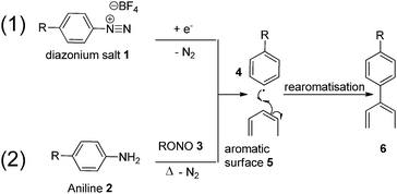
The use of diazonium species for graphitic surface functionalisation has earned a reputation as a highly versatile and reliable methodology, with demonstrated applications ranging from modified semi-conductors and electrodes, to soluble carbon nano-horns, and the tethering of ruthenium complexes to carbon surfaces.32–35 There are two different and equally effective methodologies for carrying out successful surface functionalisation using diazonium species. In the first (Fig. 1, Path 1, top), an appropriate diazonium salt (usually with a charge diffuse counter-ion, in this case BF4) is first synthesised and isolated, followed by removal of the diazo moiety at a carbon electrode in an electrolytic solution.36 Alternatively (Fig. 1, Path 2, bottom), an aniline is added to a solution of acetonitrile/H2O and an organic nitrite, allowing in situ formation of a diazonium intermediate, followed by reaction with the carbonaceous surface.34
Functionalisation pathway (1), while effective, involves the synthesis and isolation of unstable diazo-intermediates, such as 1, and requires the intended surface to be functionalised (5) to be assembled at a single uniform anode for successful functionalisation to occur.
This approach was examined in the late 1990s by Pinson who used electrochemical methods to graft an aniline onto the surface of carbon fibres.37,38 That work suggested that the grafting led to an enhanced interfacial interaction though single fibre characterisation, surface analysis by XPS/AFM and interfacial shear strength were not determined. In contrast, pathway two begins with a common and stable anilinic compound 2 (simple variations of which can be purchased commercially), and requires only heating in solution, with an alkyl nitrite 3, to generate reactive intermediate 4in situ which is then directly reacted with the electron rich surface, bypassing the need to isolate any intermediate material. Considering the positive implication of surface modification via this type of reaction implied by Pinson, we wished to examine diazonium grafting in more detail to gain a better understanding of the effects of individual fibres and the corresponding effect on interfacial shear strength.
With the large number of examples demonstrating the effectiveness of the diazonium species for surface modification of graphene and CNT materials, we considered this methodology to be highly suitable for carbon fibre. To further complement this approach, a myriad of aniline functionalisation techniques are well established in the literature, allowing for near limitless customisation of the molecule to be grafted onto the surface.39–43 In our continuing interest to promote the covalent interaction of small molecules grafted onto the surface of carbon fibre to the epoxy resin we saw this as a unique opportunity to further our goals in this area utilising established protocols. Pathway (2) allows the introduction of new chemical moieties capable of increasing polarity of the fibre surface by reacting with the abundant graphitic surface, and reacting covalently with an epoxide based resin. The synthesis of suitable analogues is both tailorable and scalable.
In this manuscript, we have demonstrated for the first time the successful novel application of a simple and X-ray Photoelectron Spectroscopy (XPS) detectable anilinic compound to unoxidised carbon fibre using diazonium chemistry. The synthesis of a second, more complex analogue was then undertaken, followed by attachment to unsized oxidised carbon fibre to demonstrate methodological broadness and applicability. The effectiveness of the treatment was assessed by measuring interfacial shear-strength (IFSS) of the treated fibres embedded in an epoxy matrix.
Results and discussion
Preliminary study – functionalisation of unoxidised fibre via in situ formation and degradation of a phenyldiazo derivative
The application of organic chemistry techniques to carbon fibre is a relatively new field of research and as such, the development of a new functionalisation method requires a proof of concept step. We began this process by first designing an “ideal” sample; one which could be easily synthesised from simple starting materials while including both the required aniline attachment point and a tag for XPS detection, in this case a nitro (NO2) moiety. It was proposed that an analogue could be made from 4-aminophenol (a cheap and readily available material), via a three step synthesis: (i) protection of the amine, (ii) Williamson ether synthesis, and finally (iii) revealing the anilinic nitrogen by deprotection (Scheme 1) on a relatively large laboratory scale (2–3 g). | ||
| Scheme 1 Conditions (i) Boc2O, NaHCO3, NaCl, CH2Cl2/H2O, 50 °C, 2 h; (ii) 4-nitrobenzyl bromide, KOH, NaI, acetone, 55 °C, 16 h; (iii) TFA, CH2Cl2, 12 h. | ||
The intended synthesis proceeded well; protection of aniline 7 with t-butoxycarbamate gave phenol 8 in excellent yield (81%), Williamson ether synthesis under Finkelstein conditions proceeded well in good yield (64%). Deprotection of 9 using trifluoroacetic acid in DCM (20% v/v) gave the corresponding target 10 as the free amine after work-up in good yield (77%).
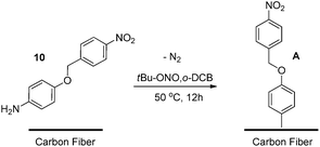
It was then rationalised that to minimise sample analysis complications as well as any unpredictable side reactions, an “ideal” carbon fibre should also be used. To this end, a sample of carbon fibre which had not undergone electrolytic oxidation was sourced, as it was proposed that the surface would contain a higher graphitic component compared with an oxidised fibre sample. Treatment of the unoxidised carbon fibre with novel nitro aniline 10 was carried out by adapting established diazonium formation protocols applied to carbon nanomaterials, removing any mechanical agitation to prevent fibre damage (Scheme 2). The fibres were then thoroughly rinsed under vacuum filtration with a series of AR grade organic solvents to remove any residual solvent or unreacted starting materials, followed by 24 hours of drying under reduced pressure.
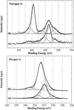
Analysis by XPS of the resulting fibres (Scheme 2, A) revealed interesting changes regarding the surface chemical composition compared to the control fibres. These changes were particularly evident in the high resolution O1s and N1s spectra and curve-fitting was used in an attempt to identify contributions from different functional groups (Fig. 2).44 Considering the complexity of the carbon fibre surface a comprehensive characterisation would require a range of different techniques and is clearly beyond the scope of this study. Here we focus on the observed changes after surface modification to validate this analysis technique and provide confidence when grafting on more complex small molecules (discussed below). The N1s of the untreated sample (Fig. 2, top) provided evidence for a range of nitrogen and nitrogen–oxygen species including N–C/N![[double bond, length as m-dash]](https://www.rsc.org/images/entities/char_e001.gif) C (399 eV), N–C–O/N–C
C (399 eV), N–C–O/N–C![[double bond, length as m-dash]](https://www.rsc.org/images/entities/char_e001.gif) O (400–401 eV) and possible charged species such as protonated amines (>402 eV). The dominant O1s component at just below 532 eV is consistent with oxygen–nitrogen based species such as N–C
O (400–401 eV) and possible charged species such as protonated amines (>402 eV). The dominant O1s component at just below 532 eV is consistent with oxygen–nitrogen based species such as N–C![[double bond, length as m-dash]](https://www.rsc.org/images/entities/char_e001.gif) O (Fig. 2, bottom). The N1s spectrum of the treated sample showed the appearance of a strong peak at ∼405.5 eV, clear evidence for the introduction of a nitro species onto the fibre surface. Successful functionalisation of the fibre was supported by the notable increase in oxygen; both the nitro moiety (NO2) and ether linkage (R-O-R′) of the diazonium product would give rise to an O1s signal at ∼532.5–533 eV which is clearly evident in the O1s spectrum of the treated fibre.
O (Fig. 2, bottom). The N1s spectrum of the treated sample showed the appearance of a strong peak at ∼405.5 eV, clear evidence for the introduction of a nitro species onto the fibre surface. Successful functionalisation of the fibre was supported by the notable increase in oxygen; both the nitro moiety (NO2) and ether linkage (R-O-R′) of the diazonium product would give rise to an O1s signal at ∼532.5–533 eV which is clearly evident in the O1s spectrum of the treated fibre.
Furthermore, there was no notable increase in other baseline nitrogen species, suggesting there was complete conversion of the aniline to the diazo species, and no residual starting material present on the fibre surface. With the XPS analysis strongly suggesting the presence of the nitro compound, a series of preliminary mechanical assessments were undertaken to understand the effects of the treatment on important physical properties; the results of which demonstrated no loss in elastic modulus, tenacity, or changes to fibre topography (see ESI†).
Synthesis of 14 and 16 and surface functionalisation of oxidised unsised carbon fibres
With the encouraging results from the proof of concept study, a second more complex aniline analogue was designed to structurally elaborate on the functionalisation methodology. The target compound was designed such that it would include three key components: (i) an aniline moiety for carbon fibre attachment; (ii) an XPS tag for ease of characterisation (CF3), and; (iii) an amine available for reaction with an epoxide based resin (Fig. 3).To emulate more closely an industrially relevant carbon fibre sample, and to maximise tenacity of the base fibre,45 from this point on in this study all compounds were attached to oxidised carbon fibre. To be clear regarding the state of this fibre, it has undergone carbonisation and electrolytic oxidation but has not undergone any sizing treatments. This same fibre is also used as the control samples for all analysis which are presented in this manuscript as to provide an impartial comparison to the surface treated fibres. While the oxidation process does affect the surface chemistry of the fibres, there are still ample graphitic sites present on the surface which can undergo reaction with the in situ generated diazonium species.
A generic structure of the desired compound was proposed (Fig. 3), and we considered a hydrophilic linker to be optimal as this may increase the surface polarity and enhance the ‘wettability’ as is desirable for good dispersion within curing resins.
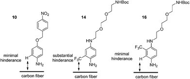
With these considerations in mind, target compounds 14 and 16 were designed, each bearing the trifluoromethyl group at a different relative position to the anilinic nitrogen (ortho and meta, respectively) the eventual point of attachment to the carbon fibre surface.
These compounds were synthesised using the same methodology shown in Scheme 3. This began with diamine 11, to introduce both polarity, and a bi-functional synthetic handle. After selective mono-protection of the diamine (Boc was chosen to maintain amine protection/deprotection orthogonality) to obtain 12. Treatment of this amine with 5-fluoro-2-nitrobenzotrifluoride gave 13 followed by reduced to 14 using Pd/C in a hydrogen atmosphere, revealing the anilinic nitrogen for attachment to carbon fibre. Access to 16 was achieved via the same protocol but replacement of 5-fluoro-2-nitrobenzotrifluoride with 2-fluoro-5-benzotrifluoride (thus giving the CF3 group at the alternate position), giving 15, again followed by reduction of the nitro moiety by Pd/C and hydrogen gas resulting in formation of 16.
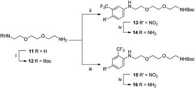 | ||
| Scheme 3 Conditions: (i) Boc2O, CH2Cl2, 16 h; (ii) 5-fluoro-2-nitrobenzotrifluoride DMF, 100 °C, 80 min; (iii) 2-fluoro-5-benzotrifluoride, DMF, 100 °C, 80 min; (iv) H2, Pd/C (10% w/w), MeOH, 16 h. | ||
The alkyl amine terminating the oxyethylene chain remained protected with the butoxycarbamate group at this stage to negate any side-reactions or interference from the alkyl amine during in situ diazotisation. It was envisaged that removal of the carbamate to reveal the nucleophilic nitrogen would be carried out after attachment to the carbon fibre surface.
The same diazonium protocol established in the preliminary study was then applied to the functionalisation of oxidised fibre using both 14 and 16 (Scheme 4). This was followed by the same rigorous rinsing and drying conditions to ensure complete removal of unreacted materials and solvent. In the interest of thoroughness, a negative control was also carried out using identical reaction and cleaning conditions (without 14/16 or t-BuONO present) to rule out the effects of solvent adsorption in chemical analysis.
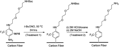 | ||
| Scheme 4 Functionalisation of oxidised carbon fibre using diazonium formation of 14 and 16, and the subsequent deprotection protocol. | ||
Finally, removal of the tert-butoxy (Boc) protecting group was carried out to yield a free amine, which could interact covalently with an epoxy resin. With no published examples of solid phase Boc-deprotection on a carbon fibre surface, once again appropriate reaction conditions had to be developed by adapting protocols used for application to carbon nanomaterials.46,47
After an extensive literature search, two appropriate methods were identified, the first involved suspending the fibres in a solvent followed by saturation with gaseous HCl, or suspension of the fibres in a pre-acidified organic solution (e.g., HCl in 1,4-dioxane) to facilitate deprotection. In the interests of safety and scalability, the second approach was considered the more appropriate, thus a 2 M HCl/dioxane solution was prepared in-house. Approximately 80% of the fibres which had undergone surface functionalisation by treatment 1 (the remaining 20% reserved for chemical and physical characterisation) were immersed in the HCl solution and allowed to react for 16 hours to ensure sufficient exposure to acid (Scheme 4, treatment 2). This was followed by thorough rinsing under vacuum.
The fibres were then basified using a 2 M solution of NaOH (in Milli-Q water), and rinsed thoroughly a second time to afford the free amine (Scheme 4, treatment 2). As before, a negative control sample (untreated oxidised fibre) was subjected to the same deprotection protocol.
As described above analysis of the surface elements was undertaken using XPS, this was done on fibres which had undergone functionalisation, the oxidised and unsized fibre used as the starting materials, and their respective controls samples (Table 1). It was found that fibres which had undergone surface functionalisation using compound 14 showed very little evidence of successful compound grafting (for values from XPS analysis refer to ESI†). Conversely, the same protocol using 16 showed good levels of compound grafting to the surface. An increase in fluorine ratio (Table 1), from 0 F/C for the untreated oxidised sample, to 0.020 and 0.015 for treatment 1 and 2, respectively, was observed.
| Treatment | Control | A | B | 1 | 2 | C | D |
|---|---|---|---|---|---|---|---|
| a A = Fibres have been immersed in refluxing organic solvent and thoroughly cleaned. B = As per A (above) in addition to tert-butyl nitrite and fibres were briefly rinsed clean. C = As per B, with a more intense fibre cleaning procedure. D = The fibres from treatment C have been immersed in 2 M HCl in dioxane and then thoroughly rinsed. | |||||||
| Previous treatment | None | None | None | None | Treatment 1 | None | Treatment C |
| Reagents | None | None | t-Butyl nitrite | t-Butyl nitrite, aniline 16 | HCl, NaOH | t-Butyl nitrite | HCl, NaOH |
| Solvent | None | o-DCB/MeCN | o-DCB/MeCN | o-DCB/MeCN | 1,4-Dioxane/H2O | o-DCB/MeCN | 1,4-Dioxane/H2O |
| Conditions | None | 50 °C, 24 hours | 50 °C, 24 hours | 50 °C, 24 hours | r.t., 16 hours | 50 °C, 24 hours | r.t., 16 hours |
| Cleaning | None | DCM, acetone, EtOH | Rinse only | DCM, acetone, EtOH | H2O, acetone | DCM, acetone, EtOH | H2O, acetone |
| Element | ||||||||||||||
|---|---|---|---|---|---|---|---|---|---|---|---|---|---|---|
| Mean | Dev. | Mean | Dev. | Mean | Dev. | Mean | Dev. | Mean | Dev. | Mean | Dev. | Mean | Dev. | |
| C | 1.000 | 0 | 1.000 | 0 | 1.000 | 0 | 1.000 | 0 | 1.000 | 0 | 1.000 | 0 | 1.000 | 0 |
| N | 0.048 | 0.001 | 0.044 | 0.002 | 0.041 | 0.001 | 0.049 | 0.001 | 0.040 | 0.001 | 0.039 | 0 | 0.038 | 0 |
| O | 0.068 | 0 | 0.074 | 0.001 | 0.084 | 0.001 | 0.110 | 0.003 | 0.082 | 0.006 | 0.089 | 0.003 | 0.056 | 0 |
| F | 0.000 | 0 | 0.000 | 0 | 0.000 | 0 | 0.020 | 0 | 0.015 | 0 | 0.000 | 0 | 0.000 | 0 |
This increase can be attributed to the presence of the CF3 functionality on the new analogue (Table 1), with the proposed diazonium reaction introducing the functionality during treatment 1. If this is indeed successful grafting this fluorine signal should remain after the deprotection step (treatment 2), which was reflected in the results. Additionally there is a slight increase in oxygen concentration, for both 1, and 2 which can be linked to the introduction of the analogue to the surface of the carbon fibre. Unfortunately this was not reflected in the nitrogen ratio, which remained consistent across all samples. To understand further the changes in surface chemistry as a result of functionalisation with 16, high resolution spectra were collected for each of the elements of interest (C, O, and N).
As with previous attempts to characterise treated carbon fibre using XPS,45 it is very challenging to quantify any data from the C1s/N1s and O1s spectra of carbon fibre surfaces given the heterogeneity of the fibre surface.20 This complexity is thought arise from uncarbonised PAN, various carbon morphologies and oxidation states which occur during fibre manufacture. It is for this reason that we chose the fluorine as our XPS visible group as it is unique to our compound and is not involved in the production of the fibres at any step.
In each of the control fibre preparations (A, B, C and D) we found that the wet chemistry techniques (e.g. washing with various organic solvents) tended to remove some of the nitrogen content from the surface of the fibre. Curve-fitting of the N1s high resolution peak showed that this was mainly due to a decrease in intensity of the N1s signal between 399 and 400 eV, indicating a loss of amine and/or amide type species (data shown in ESI†). Presumably this reflects the removal of some nitrogenous contamination present from the production of the fibres from the PAN-based precursor.
Interestingly, when the fibres underwent functionalisation (treatment 1) the oxygen, fluorine and nitrogen content increased, despite using the same methodology which was shown to decrease surface bound nitrogen in samples A, B and C. These data support functionalisation as oxygen, nitrogen and fluorine are imperative to identifying our compound on the fibre surface. We performed a careful analysis of the C1s and O1s spectra, including curve-fitting, in the interest of thoroughness, and the results are included in the ESI.† However, the overall changes in oxygen and nitrogen were small and no specific and statistically significant conclusions were possible. Sample D, a control samples for deprotection after treatment C, shows that no fluorine was added to the surface after treatment with acid and subsequent washes, as expected. Nevertheless, it was still present for the deprotected sample 2 which had previously undergone functionalisation.
Regarding the inability to successfully graft the fibres using compound 14, this result was attributed to the poor anilinic nitrogen nucleophilicity of 14. The electronic nature of 14versus16 is effectively the same and thus we reasoned that the poor reactivity was due to steric impedance introduced by the CF3 group at the ortho-position, relative to the NH2 (Fig. 4).
This steric influence can have several effects, (i) the inability of 14 to react with the t-butyl nitrite and thus no surface grafting occurs due to the inability to undergo diazotisation, or (ii) diazotisation occurs to a small extent but the approach of 14 to the surface is, again, impeded by the CF3 group. Indeed, this would be consistent with the observations made for successful grafting of 10 and 16 which have no steric obstruction.
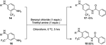
As a means to examine and compare the reactivity between 14 and 16, a simple N-acylation experiment was undertaken using strictly equimolar amounts of reagents at low temperature (Scheme 5).
The results obtained after purification showed a clear distinction between the performances of the two analogues. The ortho substituted aniline 14 gave only trace conversion to 17, attempts to isolate the material proved fruitless as there was so little material. Conversely, the meta-substituted aniline 16 vastly outperformed 14 giving 18 in an excellent isolated yield of 85%. Although this reaction does not directly represent the in situ formation of diazonium species and subsequent functionalisation, it gave some insight into the relative reactivity of the two compounds. Additionally, this result suggests that steric effects are playing a more important role in this scenario than any amine deactivation induced by the trifluoromethyl group.
Single fibre tenacity, friction coefficient and elastic modulus
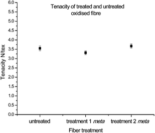
With the chemical characterization consistent with successful functionalisation, and the improvement in reactivity of the new complex analogue apparent, the next important step involved the assessment of critical mechanical parameters. Note: all of the following analyses to be discussed concern only fibres which have undergone functionalisation with 16. The corresponding physical data for fibres exposed to functionalisation conditions in the presence of 14, despite minimal functionalisation, are provided in the ESI.†The investigation of these properties began by determining the tenacity (standardised using linear density), to understand the effects on fibre strength by introducing new functionalities onto the surface as well as exposure to different reaction conditions. When fibres from both treatment 1 and treatment 2 were compared to that of untreated oxidised fibres, no significant changes in tenacity, as a result of either chemical treatment steps, were observed (Fig. 5). This suggests that while the reaction covalently attaches the diazonium compounds to the graphitic surface, it does not compromise the integrity and strength of the fibre.
Although the systematic measurement of tenacity under highly controlled physical parameters can give a large amount of information about fibre properties, it still has limitations. Because carbon fibres exhibit brittle failure under strain, and failure is dependent on the distribution of flaws or defects in the specimen; the random distribution of strength-limiting defects means the tenacity of carbon fibre is sensitive to gauge length when physically measured.48
To gain more insight into this parameter the data collected was subjected it to secondary processing using the Weibull equation.48,49 It is worth noting that more complex models exist, developed by D. D. Edie et al. which provide detailed information regarding fibre strength and the ability to predict strength at small gauge lengths.50,51 In this study a two parameter Wiebull distribution was used and achieved a good representation of the tensile strength and experimental data. This is consistent with our previous work.45,52
Analysis of each sample confirmed that the fibre strengths correlated well to Weibull distributions (Table 2) with r2 values above 0.95. The characteristic strength values also correlated well to the measured tenacity: from 3.5 vs. 4.1 N per tex for the untreated sample, 3.3 vs. 3.6 N per tex for treatment 1, and 3.7 vs. 4.1 N per tex for treatment 2. Additionally, Weibull moduli (shape parameters) were consistent across the three samples, with a range from 3.76 to 4.62, suggesting a similar probability of failure by critical flaws.
| Treatment | Weibull analysis | ||
|---|---|---|---|
| Modulus (shape parameter) | Characteristic strength (N per tex) | r 2 | |
| None | 4.04 | 4.11 | 0.9652 |
| Treatment 1 | 4.62 | 3.63 | 0.9780 |
| Treatment 2 | 3.76 | 4.14 | 0.9676 |
Moving on to the specific modulus (elastic modulus) of individual carbon fibres, this parameter can have a considerable influence over the bulk properties of a final composite, with high modulus fibres highly sought after for specialised performance parts. As such, it was of great interest to investigate whether the treated fibres had retained the same modulus properties as those sourced from industry. Interestingly after data collection using the Favimat, analysis showed that after treatment 1 showed no change in specific modulus, but after treatment 2 fibres showed a slight increase in modulus (Fig. 6). Thus, the combined analyses of tenacity and modulus strongly suggested that the treatments had not significantly altered the crucial strength and stiffness character of the fibres.
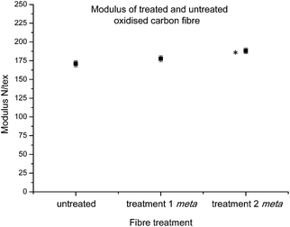 | ||
| Fig. 6 Average modulus control carbon fibres and fibres functionalised with 16 after treatments 1 and 2 (statistically significant data denoted *). | ||
The coefficient of friction (CoF) of individual fibres against polished stainless steel pins was investigated next. This property is important for fibre performance, as the friction at the carbon fibre/resin interface plays an important role in mechanical interlocking of the composite.53
Previous investigations conducted within this research group,45 have found trends which suggest that a heightened CoF value may be related to the successful introduction of new chemical functionalities. The CoF values determined for functionalised fibres after both treatments 1 and 2, showed significant changes in comparison to the control carbon fibre (Fig. 7). As the chemical characterisation by XPS strongly suggests the successful introduction of the diazonium analogue on to the carbon fibre surface, this result seems to be consistent with our previous observations.45
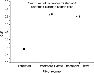 | ||
| Fig. 7 Average coefficient of friction control carbon fibres and fibres functionalised with 16 after treatments 1 and 2 (statistically significant data denoted *). | ||
Analysis of fibre roughness and topography by AFM
With a thorough understanding of the mechanical properties of the individual fibres, the next step involved analysis of changes in important physical characteristics or damage as a result of fibre treatment. Atomic force microscopy was employed to analyse the general surface features of the treated and untreated fibres, and to detect any changes in nanoscale roughness after treatment.A number of contact mode height images were taken of each sample (9 for each), with one typical image shown here (Fig. 8). Upon visualisation of the surface topographies, it can be seen that there is no noticeable changes in the fibre structure or obvious damage (see ESI† for the remaining images); this suggests that the treatments employed do not interfere with the fibres microscopic structure or integrity.
 | ||
| Fig. 8 Representative height images for (a) untreated (oxidised and unsized) and treated samples (16), (b) treatment 1, (c) treatment 2. | ||
This observation was further confirmed by roughness analysis, which showed no statistical differences in average roughness when compared to the untreated fibre (Fig. 9), although it should be noted there was a large amount of variation in roughness even within two spots on the same continuous fibre, highlighting the heterogeneous nature of the material.20
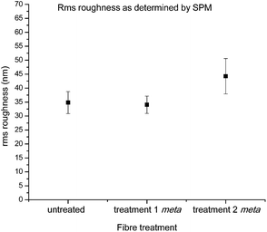 | ||
| Fig. 9 Calculated rms roughness for 1 × 1 μm images of control carbon fibres and fibres functionalised with 16 after treatments 1 and 2 (statistically significant data denoted *). | ||
Determination of interfacial shear strength using single fibre fragmentation
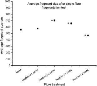
With the fibres functionalised with 16 in hand, and both chemical and single fibre analysis complete, focus shifted to determining if the attachment of pendant nitrogen moieties onto the fibre surface would enhance the interfacial shear strength. A thorough review of the literature revealed a number of techniques available for the determination of carbon fibre to matrix bond strength. In this study Single Fibre Fragmentation Technique (SFFT) proved to be the most representative analysis for the fragile fibre/ductile matrix carbon fibre/epoxy composites.54 In the interest of thoroughness, the entire suite of both ortho- and meta-analogues, 14 and 16, respectively, were tested using SFFT to understand any subtle differences between the two analogues and their single fibre composite performance.According to the Kelly–Tyson model for determining interfacial shear-strength (IFSS), the average fragment size after the fragmentation test is a key indicator of bond strength. Smaller fibre fragments within the specimen implies increased efficiency with which load is transferred from the epoxy resin to the fibre itself. This effect is facilitated by the degree of interaction between fibre and the resin matrix.55 The average fragment sizes of the 14 functionalised fibres showed an unexpected trend (Fig. 10), with the value being similar to that of the control fibres after treatment 1, but increasing after treatment 2.
Conversely, the results of the fragments size after treatment with 16 showed the opposite effect after each treatment, with treatment 1 giving an increased fragment size, followed by a marked decrease after treatment 2.
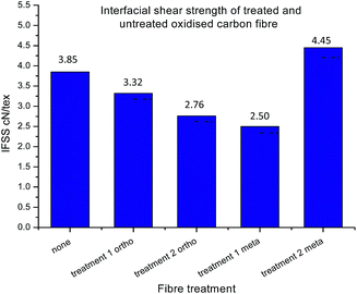
Whilst improved fibre–matrix adhesion will lead to shorter fragments, the final fragment size will also be influenced by the strength of the fibre and the spread of failure properties. This is captured by measuring the IFSS which, as shown in eqn (5), is a function of fragment size, specific strength (σ) and Weibull modulus (m). When the fibre is treated with the ortho- compound 14 the IFSS decreases after both treatment 1, and treatment 2 (Fig. 11), it was rationalised that the decrease in IFSS observed could be due to a “cleaning” effect purely from the reaction conditions. This is consistent with previous observations from the XPS data, in which the presence of nitrogenous species on the surface of the fibres was decreased after controls A, B and C.
During treatment 1 the fibres are immersed and boiled in solvent (o-DCB, acetonitrile) for 24 hours, and it is possible that even the exposure to these conditions could further remove impurities from the surface without introducing new functionalities, theoretically decreasing the degree of bonding between the fibre and matrix. Again, the exposure to 2 M acid for 24 hours in treatment 2 could have a similar and compounding effect of removing impurities which was reflected with an even larger decrease in IFSS after treatment of these fibres in 2 M HCl.
It was expected that functionalisation of oxidised and unsized fibre with 16 (treatment 1 only) would result in a decrease in IFSS, as there is no free amine to react covalently with the resin. Though after treatment 2, revealing the reactive nitrogen, with fibres functionalised with 16, a marked increase in IFSS was observed, higher than that of the control sample.
With the possibility of the added cleaning effect from treatment 1 and 2 combined, the deprotection step has not only overcome the decrease in IFSS which may happen as a result of the reaction conditions, but revealed reactive moieties on the surface which significantly improved the performance of the single fibre composite material. Note that representative images for each of the samples are presented in the ESI,† in addition to the distribution of fragment length.
Conclusion
In conclusion, we have successfully shown the application of in situ generated diazonium surface functionalisation technology to carbon fibres. The steric considerations of the organic scaffold to be attached to the surface must be taken into consideration to ensure an appreciable amount of surface grafting occurs. The influence of ortho-substitution relative to the attachment point on nucleophilicity and accessibility was highlighted in this work and was shown using a comparative reaction rate in an N-acylation methodology. Grafting of a sterically unencumbered anilinic scaffold, such as 16, showed successful grafting to the fibre surface and showed no adverse effects on fibre integrity or any appreciable loss in overall fibre tenacity. Large increases to the coefficient of friction were observed for the functionalised fibres which is consistent with our previous observations. Determination of roughness by SPM showed that no morphological changes had occurred on the fibre surface, despite the increase in coefficient of friction. Determination of IFSS showed a large increase for the functionalised fibres which possessed a nucleophilic amine on the surface of the fibres.Materials and methods
Carbon fibre samples (Panex 35 unsized/oxidised tow not having undergone sizing) were supplied by Zoltek carbon fibre, Hungary and used as supplied. All chemicals, reagents and solvents were purchased from Sigma-Aldrich Chemical Company and used as received.Fibre treatment protocols
Preliminary study – synthesis and fibre functionalisation using a nitro aniline diazonium species
A solution of ortho-dichlorobenzene (30 mL), acetonitrile (15 mL) and nitro compound 10 (250 mg, 0.75 mmol) was degassed in a 250 mL round bottom flask under a steady flow of nitrogen for 1 hour. A sample of unoxidised carbon fibre (350 mg) was then added to the solution under a nitrogen atmosphere and fully submerged in the solution, followed by addition of tert-butyl nitrite (1.9 equiv. 162 μL, 1.4 mmol). The reaction vessel was then placed in an oil bath at 50 °C and fitted with a reflux condenser under nitrogen atmosphere, and allowed to react for 24 hours. Upon reaction completion, the solution was decanted followed by resuspension and manual agitation in chloroform (repeated until solution is clear). The fibres were then transferred to a Buchner funnel and rinsed with equal portions of dichloromethane, ethanol and acetone (200 mL) under vacuum filtration; followed by drying under reduced pressure for 24 hours to yield the functionalised product.Treatment 1 – CF3 aniline diazonium reaction
A solution of ortho-dichlorobenzene (60 mL), acetonitrile (30 mL) and fluorinated aniline (1 equiv.) were reacted according to the above procedure.Treatment 2 – butoxycarbamate (Boc) deprotection conditions
The functionalised sample was placed in a 100 mL round bottom flask, and fully immersed in an anhydrous solution of HCl in 1,4-dioxane (2 M, 20 mL). The solution was allowed to react at room temperature for 24 hours, after which, the HCl/dioxane was decanted and the fibres washed with 3 portions of Milli-Q water (150 mL) to ensure removal of acid. The fibres were then basified using a Milli-Q/NaOH solution (2 M, 3 × 20 mL), with each separate addition of hydroxide first manually agitated, then allowed to sit for ten minutes to allow reaction to complete. Base was then removed with 5 × 50 mL portions of Milli-Q water, followed by transfer of the fibres to a Buchner funnel and rinsed under vacuum filtration with acetone (150 mL). The sample was then dried in a desiccator under reduced pressure for 24 hours to yield a free amine.Chemical characterisation technique
X-ray photoelectron spectroscopy
XPS analysis was performed using an AXIS Ultra-DLD spectrometer (Kratos Analytical Inc., Manchester, UK) with a monochromated Al Kα source (hν = 1486.6 eV) at a power of 150 W (15 kV × 10 mA), a hemispherical analyzer operating in the fixed analyzer transmission mode and the standard aperture (analysis area: 0.3 mm × 0.7 mm). The total pressure in the main vacuum chamber during analysis was typically below 10−8 mbar.Bundles of fibres were suspended across a custom-designed frame attached to standard sample bars. This ensured that only the sample to be analysed was exposed to the X-ray beam and that any signal other than that originating from carbon fibres was excluded. Each specimen was analysed at two different locations at a photoelectron emission angle of 0° as measured from the surface normal (corresponding to a take-off angle of 90° as measured from the sample surface). Since the microscopic emission angle is ill-defined for fibres the XPS analysis depth may vary between 0 nm and approx. 10 nm (maximum sampling depth).
Data processing was performed using CasaXPS processing software version 2.3.15 (Casa Software Ltd., Teignmouth, UK). All elements present were identified from survey spectra (acquired at a pass energy of 160 eV). To obtain more detailed information about chemical structure, C1 s, O1 s and N1 s high resolution spectra were recorded at 20 eV pass energy (yielding a typical peak width for polymers of 1.0 eV). If required these data were quantified using a Simplex algorithm in order to calculate optimised curve fits and thus to determine the contributions from specific functional groups.
The atomic concentrations of the detected elements were calculated using integral peak intensities and the sensitivity factors supplied by the manufacturer. Atomic concentrations are given relative to the total concentration of carbon as follows: the concentration of a given element X was divided by the total concentration of carbon and is presented here as the atom number ratio (or atomic ratio) X/C. This value is more robust than concentrations when comparing different samples. Binding energies were referenced to the aliphatic hydrocarbon peak at 285.0 eV. The accuracy associated with quantitative XPS is ca. 10–15%.
Precision (i.e. reproducibility) depends on the signal/noise ratio but is usually much better than 5%. The latter is relevant when comparing similar samples.
Physical characterisation techniques
Single fibre tensile testing
Samples were tested on a Favimat + Robot 2 single fibre tester (Textechno H. Stein) which automatically records linear density and force extension data for individual fibres loaded into a magazine (75 samples) with a pretension weight of 80 ± 5 mg attached to the bottom of each carbon fibre.Linear density was recorded using a length of 10 mm and a tension of 0.15 mN (as per supplier specifications). It is reported in units of tex where 1 tex equals 1 g km−1. Tensile load extension curves were collected at 1.0 mm min−1 using a gauge length of 10 mm and a pretension of 1.0 cN per tex. Load data was normalised by dividing by the linear density to give specific stress–strain curves from which fibre strength (ultimate specific stress or tenacity) and specific (elastic) modulus could be determined (as calculated by the instrument's software). The mean tenacity values were determined and since the statistical distribution of carbon fibre strengths is usually described by a weakest link model, the strengths were also analysed by the two-parameter Weibull cumulative distribution function to fit the experimental results (P), given by the equation:
 | (1) |
 | (2) |
Fibre friction analysis
Friction was analysed using a Favimat + Robot 2 equipped with a friction analysing unit (Textechno H. Stein). Each individual carbon fibre, with a pretension clip of 80 ± 5 mg attached to the bottom of the fibre, was pulled through the three pronged friction clamp (polished stainless steel) at a speed of 20 mm min−1. The average force (F1) was recorded whilst 25 mm of the fibre was drawn through the clamps. The coefficient of friction (μ) was calculated from the capstan equation of friction, F1 = F0![[thin space (1/6-em)]](https://www.rsc.org/images/entities/char_2009.gif) exp(μθ),56 where F0 is the initial static load or pretension, and θ is the total angle in radians subtended by the length of the fibre in contact with the cylinders (π radians in the case of the Favimat instrument).
exp(μθ),56 where F0 is the initial static load or pretension, and θ is the total angle in radians subtended by the length of the fibre in contact with the cylinders (π radians in the case of the Favimat instrument).
Scanning probe microscopy (SPM)
Interfacial shear strength (IFSS) analysis
Six individual fibres from each sample were prepared by placing each fibre down the centre of a dog-bone shaped mould, with each end of the fibre pre-tensioned using 450 mg weights to ensure it was kept straight and centred within the mould. Epoxy resin RIM935 was then mixed with hardener RIM937 in a 5![[thin space (1/6-em)]](https://www.rsc.org/images/entities/char_2009.gif) :
:![[thin space (1/6-em)]](https://www.rsc.org/images/entities/char_2009.gif) 2 w/w ratio, and air bubbles removed under reduced pressure to remove voids. The resin mixture was then poured carefully into each of the six moulds, taking care to immerse the fibres fully, before allowing the samples to cure at room temperature for 48 hours, and further post-cured at 100 °C for 12 hours. The cured samples were then ground to approximately 1.5 mm thickness, followed by polishing with 9 μm and 3 μm diamond microbeads respectively to ensure maximum uniformity and transparency. The approximate dimensions of the final test coupon are 25 mm × 5 mm × 1.5 mm.
2 w/w ratio, and air bubbles removed under reduced pressure to remove voids. The resin mixture was then poured carefully into each of the six moulds, taking care to immerse the fibres fully, before allowing the samples to cure at room temperature for 48 hours, and further post-cured at 100 °C for 12 hours. The cured samples were then ground to approximately 1.5 mm thickness, followed by polishing with 9 μm and 3 μm diamond microbeads respectively to ensure maximum uniformity and transparency. The approximate dimensions of the final test coupon are 25 mm × 5 mm × 1.5 mm.
Each coupon was then strained parallel to fibre direction using a tensile tester (Instron 5967, Instron Pty Ltd, USA), up to 8% of the total gauge length to ensure crack saturation. The samples were tested at a crosshead speed of 0.05 mm min−1 until matrix failure occurred. The test rig was equipped with a digital microscope (AD-4113 ZT Dino-Lite, AnMo Electronics Co. Taiwan), and the fibre fragmentation and saturation were monitored in situ, followed by fragment measurements using an optical microscope (High Resolution Olympus DP70, Olympus Melville NY).
Data analysis
Two sample t-test
A two-sample t-test was carried out on the data obtained for the fibre properties including: tenacity (Fig. 6), modulus (Fig. 7), coefficient of friction (Fig. 8), RMS roughness from AFM analysis (Fig. 10), and fibre fragment length from the single fibre fragmentation analysis (Fig. 11). These tests were carried out assuming equal variance, and were used to test whether data was statistically significantly different relative to the control fibres. A P-value less than 0.05 was considered statistically significant.Determination of IFSS
The average fragment length at saturation l, was calculated from the collated data of six experiments, and the critical fragment length lc calculated. This data was then used to estimate apparent shear strength at the interface (τIFSS) from the Kelly–Tyson model which is given by | (3) |
 | (4) |
 | (5) |
Acknowledgements
The authors would like to thank Abdullah Kafi for providing the fibre samples. We gratefully thank Carbon Nexus, Deakin University, LES, SEBE, CSIRO and the Australian Research Council for funding (DP140100165).Notes and references
- J. D. H. Hughes, H. Morley and E. E. Jackson, J. Phys. D: Appl. Phys., 1980, 13, 921 CrossRef CAS.
- N. Lopattananon, A. P. Kettle, D. Tripathi, A. J. Beck, E. Duval, R. M. France, R. D. Short and F. R. Jones, Composites, Part A, 1999, 30, 49–57 CrossRef.
- E. Totry, J. M. Molina-Aldareguía, C. González and J. Llorca, Compos. Sci. Technol., 2010, 70, 970–980 CrossRef CAS PubMed.
- S.-J. Park, M.-H. Kim, J.-R. Lee and S. Choi, J. Colloid Interface Sci., 2000, 228, 287–291 CrossRef CAS PubMed.
- J. D. H. Hughes, Compos. Sci. Technol., 1991, 41, 13–45 CrossRef CAS.
- I. K. Ismail and M. D. Vangsness, Carbon, 1988, 26, 749–751 CrossRef CAS.
- S. D. Fedoseev, T. V. Komarova and A. K. Zakharov, Fibre Chem., 1977, 8, 597–599 CrossRef.
- M. R. Piggott, Carbon, 1989, 27, 657–662 CrossRef.
- A. E. Standage and R. Matkowsky, Nature, 1969, 224, 688–689 CrossRef CAS.
- A. E. Standage and R. D. Matkowsky, Eur. Polym. J., 1971, 7, 775–783 CrossRef CAS.
- C. Zweber, Fracture Mechanics and Composite Materials: A Critical Analysis, American society for testing and materials, San Antonio, Texas, 1973, pp. 65–97 Search PubMed.
- E. Fitzer and R. Weiss, Carbon, 1982, 20, 149 Search PubMed.
- D. C. Davis, J. W. Wilkerson, J. Zhu and V. G. Hadjiev, Compos. Sci. Technol., 2011, 71, 1089–1097 CrossRef CAS PubMed.
- F. Severini, L. Formaro, M. Pegoraro and L. Posca, Carbon, 2002, 40, 735–741 CrossRef CAS.
- S.-J. Park and B.-J. Park, J. Mater. Sci. Lett., 1999, 18, 47–49 CrossRef CAS.
- Z. Dai, F. Shi, B. Zhang, M. Li and Z. Zhang, Appl. Surf. Sci., 2011, 257, 6980–6985 CrossRef CAS PubMed.
- M. D. Gilchrist and N. Svensson, Compos. Sci. Technol., 1995, 55, 195–207 CrossRef CAS.
- B. W. Kim and A. H. Mayer, Compos. Sci. Technol., 2003, 63, 695–713 CrossRef CAS.
- Y. Nakayama, F. Soeda and A. Ishitani, Carbon, 1990, 28, 21–26 CrossRef CAS.
- M. G. Huson, J. S. Church, A. A. Kafi, A. L. Woodhead, J. Khoo, M. S. R. N. Kiran, J. E. Bradby and B. L. Fox, Carbon, 2014, 68, 240–249 CrossRef CAS PubMed.
- J. Liu, Y. Tian, Y. Chen, J. Liang, L. Zhang and H. Fong, Mater. Chem. Phys., 2010, 122, 548–555 CrossRef CAS PubMed.
- N. Lopattananon, S. A. Hayes and F. R. Jones, J. Adhes., 2002, 78, 313–350 CrossRef CAS.
- G. J. Ehlert, Y. Lin and H. A. Sodano, Carbon, 2011, 49, 4246–4255 CrossRef CAS PubMed.
- U. Zielke, K. J. Hüttinger and W. P. Hoffman, Carbon, 1996, 34, 999–1005 CrossRef CAS.
- L. Li, L. Liu, H. Wan, Q. Xu, G. Cheng and J. Wen, Appl. Surf. Sci., 2009, 255, 8030–8035 CrossRef CAS PubMed.
- J. I. Paredes, A. Martínez-Alonso and J. M. D. Tascón, Carbon, 2002, 40, 1101–1108 CrossRef CAS.
- M. Ishifune, R. Suzuki, Y. Mima, K. Uchida, N. Yamashita and S. Kashimura, Electrochim. Acta, 2005, 51, 14–22 CrossRef CAS PubMed.
- J. B. Donnet and G. Guilpain, Carbon, 1989, 27, 749–757 CrossRef.
- J. L. Bahr and J. M. Tour, J. Mater. Chem., 2002, 12, 1952–1958 RSC.
- S. Banerjee, T. Hemraj-Benny and S. S. Wong, Adv. Mater., 2005, 17, 17–29 CrossRef CAS.
- A. Hirsch and O. Vostrowsky, in Functionalization of Carbon Nanotubes: Functional Molecular Nanostructures, ed. A. D. Schlüter, Springer Berlin, 2005, vol. 245, pp. 193–237 Search PubMed.
- S. Baranton and D. Bélanger, Electrochim. Acta, 2008, 53, 6961–6967 CrossRef CAS PubMed.
- S. Gam-Derouich, S. Mahouche-Chergui, M. Turmine, J.-Y. Piquemal, D. B. Hassen-Chehimi, M. Omastová and M. M. Chehimi, Surf. Sci., 2011, 605, 1889–1899 CrossRef CAS PubMed.
- G. Pagona, N. Karousis and N. Tagmatarchis, Carbon, 2008, 46, 604–610 CrossRef CAS PubMed.
- B. Jousselme, G. Bidan, M. Billon, C. Goyer, Y. Kervella, S. Guillerez, E. A. Hamad, C. Goze-Bac, J.-Y. Mevellec and S. Lefrant, J. Electroanal. Chem., 2008, 621, 277–285 CrossRef CAS PubMed.
- F. Le Floch, J.-P. Simonato and G. Bidan, Electrochim. Acta, 2009, 54, 3078–3085 CrossRef CAS PubMed.
- P. Allongue, M. Delamar, B. Desbat, O. Fagebaume, R. Hitmi, J. Pinson and J.-M. Savéant, J. Am. Chem. Soc., 1997, 119, 201–207 CrossRef CAS.
- M. Delamar, G. Désarmot, O. Fagebaume, R. Hitmi, J. Pinson and J. M. Savéant, Carbon, 1997, 35, 801–807 CrossRef CAS.
- A. Mekki, S. Samanta, A. Singh, Z. Salmi, R. Mahmoud, M. M. Chehimi and D. K. Aswal, J. Colloid Interface Sci., 2014, 418, 185–192 CrossRef CAS PubMed.
- E. Lebègue, T. Brousse, J. Gaubicher and C. Cougnon, Electrochim. Acta, 2013, 88, 680–687 CrossRef PubMed.
- M. Liu, Y. Duan, Y. Wang and Y. Zhao, Mater. Des., 2014, 53, 466–474 CrossRef CAS PubMed.
- M. E. Lipińska, S. L. H. Rebelo, M. F. R. Pereira, J. A. N. F. Gomes, C. Freire and J. L. Figueiredo, Carbon, 2012, 50, 3280–3294 CrossRef PubMed.
- N. Karousis, H. Ali-Boucetta, K. Kostarelos and N. Tagmatarchis, Mater. Sci. Eng., B, 2008, 152, 8–11 CrossRef CAS PubMed.
- G. Beamson and D. Briggs, High Resolution XPS of Organic Polymers. The Scienta ESCA300 Database, John Wiley & Sons Ltd, 1st edn, 1992 Search PubMed.
- L. Servinis, L. C. Henderson, T. R. Gengenbach, A. A. Kafi, M. G. Huson and B. L. Fox, Carbon, 2013, 54, 378–388 CrossRef CAS PubMed.
- M. A. Ghanem, I. Kocak, A. Al-Mayouf, M. AlHoshan and P. N. Bartlett, Electrochim. Acta, 2012, 68, 74–80 CrossRef CAS PubMed.
- M. A. Ghanem, I. Kocak, A. Al-Mayouf and P. N. Bartlett, Electrochem. Commun., 2013, 34, 258–262 CrossRef CAS PubMed.
- C. P. Beetz Jr, Fibre Sci. Technol., 1982, 16, 81–94 CrossRef.
- W. Weibull, J. Appl. Mech., 1951, 18, 293–297 Search PubMed.
- M. C. Paiva, C. A. Bernardo and D. D. Edie, Carbon, 2001, 39, 1091–1101 CrossRef CAS.
- E. G. Stoner, D. D. Edie and S. D. Durham, J. Mater. Sci., 1994, 29, 6561–6574 CrossRef CAS.
- L. Servinis, T. R. Gengenbach, M. G. Huson, L. C. Henderson and B. L. Fox, Aust. J. Chem., 2014 DOI:10.1071/ch14254.
- S. Zhandarov and E. Mäder, Compos. Sci. Technol., 2005, 65, 149–160 CrossRef CAS PubMed.
- P. J. Herrera-Franco and L. T. Drzal, Composites, 1992, 23, 2–27 CrossRef CAS.
- R. N. Laboratory, in Testing Procedure for Single Fibre Fragmentation Test, ed. S. Feih, K. Wonsyld, D. Minzari, P. Westermann and H. Liholt, Pitney Bowes Management Services, Denmark, 2004, pp. 1–28 Search PubMed.
- B. Cornelissen, L. Warnet and R. Akkerman, Friction measurements on carbon fibre tows, 14th International Conference on Experimental Mechanics (ICEM 14), Poitiers, France, 2010 Search PubMed.
Footnote |
| † Electronic supplementary information (ESI) available: Additional information provided includes: synthetic sequence use to isolate target compounds, all NMR spectra. In addition all AFM images and high resolution C1s and O1s spectra are provided. See DOI: 10.1039/c4ta04798b |
| This journal is © The Royal Society of Chemistry 2015 |

