 Open Access Article
Creative Commons Attribution 3.0 Unported Licence
Photoactive composite films prepared from mixtures of polystyrene microgel dispersions and poly(3-hexylthiophene) solutions†
Mu
Chen
a,
Zhengxing
Cui
a,
Steve
Edmondson
a,
Nigel
Hodson
b,
Mi
Zhou
c,
Junfeng
Yan
a,
Paul
O'Brien
ad and
Brian R.
Saunders
*a
aPolymers Composites and Carbon Research Group, School of Materials, The University of Manchester, Grosvenor Street, Manchester, M13 9PL, UK. E-mail: brian.saunders@manchester.ac.uk
bBioAFM Facility, Stopford Building, The University of Manchester, Oxford Road, Manchester, M13 9PT, UK
cCentre for Tissue Injury and Repair, Institute for Inflammation and Repair, Faculty of Medical and Human Sciences, The University of Manchester, Oxford Road, Manchester, M13 9PT, UK
dSchool of Chemistry, The University of Manchester, Oxford Road, Manchester, M13 9PL, UK
First published on 1st September 2015
Abstract
Whilst polystyrene microgels belong to the oldest family of microgel particles, their behaviours when deposited onto substrates or prepared as composites have received little attention. Because polystyrene microgels are solvent-swellable, and inherently colloidally stable, they are well suited to form composites with conjugated polymers. Here, we investigate the morphology and light absorption properties of spin coated composite films prepared from mixed dispersions of polystyrene microgels and poly(3-hexylthiophene) (P3HT) for the first time. We compare the morphologies of the composite films to spin coated microgel films. The films were studied using optical microscopy, SEM, AFM, wide-angle X-ray diffraction and UV-visible spectroscopy. The films contained flattened microgel particles with an aspect ratio of ∼10. Microgel islands containing hexagonally close packed particles were evident for both the pure microgel and microgel/P3HT composite films. The latter were electrically conducting. The composite film morphology was dependent on the microgel and P3HT concentration used for film preparation and a morphology phase diagram was constructed. The P3HT phase acted as an electrically conducting cement and increased the robustness of the films to solvent washing. The composite films were photoactive due to the P3HT component. The absorbance for the films was tuneable and increased linearly with both microgel and P3HT concentration. The results of the study should apply to other organic swellable microgel/conjugated polymer combinations and may lead to new colloidal composites for future optoelectronic applications.
Introduction
Microgel particles are crosslinked polymer colloid particles that swell in a good solvent.1–6 For non-aqueous microgel dispersions, which are the subject of the present study, colloidal stability arises from a combination of a negligible effective Hamaker constant and steric stabilisation.2 Microgels have excellent film forming properties7 and have been used in surface coatings.8 This report focuses on polystyrene microgel films and composites. Whilst films of water-swellable microgels have been well studied,9–15 there is a surprising absence of reports for polystyrene microgel films in the literature. There is only one report to our knowledge that provides any information about polystyrene microgel deformation.16 It is not clear whether non-aqueous microgels flatten to the same extent as their water based anologues. The rules governing non-aqueous microgel film formation have not been established, especially in the context of composites. There was some TEM evidence from an early study that polystyrene microgel particles deposited from ethylbenzene formed islands with a tendency toward hexagonal close packing.16 This observation is potentially useful because highly ordered particulate films have application in photonics.17,18 Here, we explore microgel ordering in films by first investigating the morphology of spin coated polystyrene microgel films. We hypothesised that the processes responsible for formation of the crystalline islands would survive inclusion into composite films provided the added polymer did not cause microgel aggregation. We investigate this hypothesis by preparing microgel/poly(3-hexylthiophene) (P3HT) composite films and studying their morphology. P3HT was selected as a linear polymer for this study for three reasons. Firstly, P3HT and linear polystyrene composites can be prepared using solution methods19 which indicates the two polymers have some miscibility. Secondly, P3HT has a higher electron density than polystyrene which was expected to increase the contrast between the two polymers for techniques such as SEM. Finally, because P3HT is photoactive20,21 its combination with colloidal films may lead to new optoelectronics applications.Polystyrene microgels are one of the oldest reported classes of microgels.22 However, it has received little attention compared to water-swellable microgels. Polystyrene microgels are usually crosslinked with divinylbenzene (DVB).16,22 They are easily prepared using surfactant-free emulsion polymerisation (SFEP),2,23 which is a scalable process. Furthermore, it is easy to tune polystyrene microgel particle size and degree of swelling using preparation conditions.24 Whilst latex films25 as well as blends of conjugated polymers with linear (insulating) polymers have been well studied19,26 the present work is the first to report composite films prepared from mixtures of solvent-swellable microgel particles with conjugated polymer solutions to our knowledge.
A number of studies that have examined the structure–property relationships for microgel films and composites prepared by depositing aqueous-swellable microgel particles.10–13,15,27–32 Schmidt et al. investigated spin coated poly(N-isopropylacrylamide-co-acrylic acid) (poly(NIPAM-AA)) microgel particles and showed that the particles were flattened.10 Wellert et al. investigated thermally-responsive acrylate-based microgel particles and also found that they were flattened.15 They also showed that the extent of thermally-triggered volume decrease was lower for the deposited particles compared to the dispersed particles. Lyon's group has published a series of papers where monolayers containing laterally compressed water-swellable microgels were studied.9,13,14,28 However, little attention has been paid to films prepared from mixtures of microgels and linear polymer. Furthermore, reports of films containing microgel mutli-layers formed in one spin coating step are scarce. The only study that has reported deposited solvent-swellable microgels to our knowledge is that by Saunders and Vincent16 which noted that polystyrene microgel particles flattened when deposited onto SEM grids from ethylbenzene. In the latter work aspect ratios were not reported and films were not prepared.
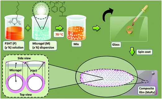
The approach used to prepare microgel/P3HT films in this work is depicted in Scheme 1. P3HT solutions and polystyrene microgel dispersions were mixed and then films deposited by spin coating. Ethylbenzene is a good solvent for polystyrene16,22 and was used in this study. The concentrations of P3HT used here were sufficiently low that the microgel/P3HT mixtures were colloidal stable. The latter simplified interpretation of the film morphologies and enhanced property control because the distribution of deposited particles within the composite films was not dominated by attractive inter-particle interactions.
Here, we present a study of photoactive films comprising microgel particle/conjugated polymer blends. First, pure spin-coated microgel films are examined to establish the microgel concentration above which the film morphology changes from that of a particle monolayer to a multilayer film. The effects of microgel and P3HT concentration on the morphology of microgel/P3HT composite films are then investigated and a morphology phase diagram constructed. The electrical conductivity and light absorption properties of the films are also studied. Several pure and composite films are shown to contain islands of crystalline microgel particles. The data reveal that P3HT behaves as an electronically conducting cement and increases the robustness of the composite films to washing with ethylbenzene. The results of this study should be generally applicable and may enable construction of microgel/conjugated polymer composites for future optoelectronic applications.
Experimental
Reagents
P3HT had a regioregularity of greater than 95% and a number-average molecular weight range of 25![[thin space (1/6-em)]](https://www.rsc.org/images/entities/char_2009.gif) 000–35
000–35![[thin space (1/6-em)]](https://www.rsc.org/images/entities/char_2009.gif) 000 g mol−1 (polydispersity < 2) and was used as received (Aldrich). Styrene (Aldrich, 99%) was purified by washing with sodium hydroxide solution. DVB (80%, Aldrich), 4,4′-azobis(4-cyanovaleric acid) (98%, Aldrich), ethylbenzene (Fisher 99.8%) were all used as received. Doubly-distilled deionised water was used for microgel synthesis.
000 g mol−1 (polydispersity < 2) and was used as received (Aldrich). Styrene (Aldrich, 99%) was purified by washing with sodium hydroxide solution. DVB (80%, Aldrich), 4,4′-azobis(4-cyanovaleric acid) (98%, Aldrich), ethylbenzene (Fisher 99.8%) were all used as received. Doubly-distilled deionised water was used for microgel synthesis.
Preparation of polystyrene microgel dispersion
The method used to prepare the polystyrene microgel was based on earlier work.16 The polystyrene microgel particles were first prepared in latex form in water using SFEP. Briefly, water (265 ml) was adjusted to a pH of 9 using aqueous NaOH solution (1 M) and then added to a 500 ml reaction vessel and stirred at 350 rpm which was heated to 70 °C. An initiator solution of 4,4′-azobis(4-cyanovaleric acid) (0.244 g, 0.871 mmol) in water, with a pH adjusted to 11.0, was prepared. DVB (0.086 g, 0.661 mmol) was mixed with styrene (28.6 g, 0.275 mol) and added to the vessel. The initiator solution was then added with stirring and the polymerisation was allowed to proceed for 3.5 h under nitrogen. The latex was subjected to repeated centrifugation and re-dispersion using water. After freeze-drying, the microgel particles were redispersed in ethylbenzene in their microgel form. The microgel had a nominal composition of 99.7 wt% styrene and 0.3 wt% DVB.Preparation of spin coated films
Pure microgel and P3HT films are identified as Mx and Py, respectively. Accordingly, M3.0 and P0.8 correspond to films deposited from a microgel dispersion or a P3HT solution containing 3.0 or 0.8 wt% solid, respectively. The composite microgel/P3HT films studied here are identified in terms of the concentrations of microgel and P3HT used for their preparation, i.e., MxPy. The M3.0P0.8 film was prepared from a mixed dispersion containing a microgel concentration (x) of 3.0 wt% and a P3HT concentration (y) of 0.8 wt%. The film was prepared by dissolving P3HT (2.0 mg) in ethylbenzene (98 mg) at 70 °C. Separately, lyophilised microgel (5.0 mg) was dispersed in ethylbenzene (95 mg) at 70 °C. Then P3HT solution (40 mg) was added to microgel dispersion (60 mg) at 70 °C. The mixed dispersion was sonicated at 70 °C until it became translucent. The mixed dispersion was rapidly added (dropwise) to a clean and dry glass slide and spin coated at 3000 rpm for 15 s using a Laurell WS-650 Mz-23NPP spin processor. (The glass microscope slides were extensively cleaned using a standard hydrogen peroxide based procedure.33) All of the other MxPy films were prepared by the same method as described above using the proper concentrations.Physical measurements
Dynamic light scattering (DLS) measurements were carried out using a 50 mW He/Ne laser operated at 633 nm with a standard avalanche photodiode and 90° detection optics connected to a Malvern Zetasizer Nano ZS90 autocorrelator. Surface profilometry measurements were conducted using a Stylus Profilometry Dektak 8 (Bruker). Films were scratched and then the height difference between the film and substrate were measured. Optical microscopy was conducted with an Olympus BX41 microscope and white transmitted light. Fractional coverage values were determined using Image J. SEM measurements were obtained using a Philips FEGSEM instrument. The accelerating voltage was 5 kV and the samples were coated with Pt. Number-average diameters (DSEM) were obtained by counting at least 100 particles. Atomic force microscopy (AFM) images were obtained using an Asylum Research MFP-3D operating in tapping mode. Imaging was performed using Olympus high aspect ratio etched silicon probes (OTESPA) with nominal spring constant of 42 N m−1 (Bruker AXS S.A.S, France). Cantilever oscillation frequency varied between 300 and 350 kHz and was determined by the auto-tune facility of the Asylum software, as was the drive amplitude. The set-point was adjusted to just below the point at which tip-sample interaction was lost to minimise sample damage. Wide-angle X-ray diffraction (WAXD) was performed using a PANalytical X'pert diffractometer. Out-of-plane diffraction patterns were measured using Cu Kα radiation. UV-visible spectra were obtained using a Hitachi U-1800 spectrophotometer. The electrical conductivity measurements were performed by Jandel multi-height four point probe station with cylindrical tungsten carbide four probe head (spacing 1.00 mm). The measurement results were recorded using a Keithley 2440 multimeter and a current of 10 mA.Results and discussion
Polystyrene microgel particle characterisation and spin-coated microgel film morphology
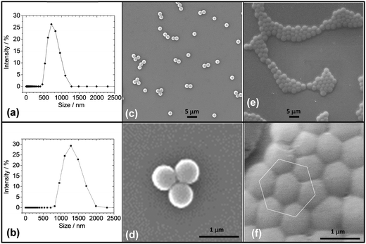
The microgel particles were prepared using SFEP following established methods.16 The particles had a z-average diameter (dz) measured by DLS of 725 nm (Fig. 1a). The particles swelled when re-dispersed in ethylbenzene (and became microgels) and the dz value increased to 1270 nm (Fig. 1b). An SEM image for the particles deposited from water in their collapsed (latex) form shows that low polydispersity particles were prepared (Fig. 1c). The number-average diameter for the particles deposited from water, DSEM(w), was 635 nm and the coefficient of variation (CV) was 7.9%. The value for DSEM(w) is smaller than the dz value for the particles dispersed in water. This difference is because dz values are more strongly affected by the larger particles within a size distribution than number-average diameters determined by SEM. It is also possible that there were some aggregates present for the aqueous latex dispersions. This study focussed on the microgel particles dispersed in a good solvent (ethylbenzene), which gave dispersions that are inherently stable.2 As discussed below the microgel particles dispersed well in ethylbenzene.The microgel particles showed a difference in their tendency to cluster during drying. The electrostatically stabilised latex particles tended to stay dispersed or form small clusters (Fig. 1c and d); whereas, the microgels deposited from ethylbenzene formed monolayer islands that were highly ordered and were effectively nanocrystals (see also Fig. 1e and f). This observation confirms an earlier TEM image.16 The present SEM data show clearly that extensive ordering occurred. It is well known that ordered close-packed 2D arrays of particles can be formed in evaporating solvent films by the process of convective assembly.34 Solvent evaporation from regions of already-ordered array (or small nucleus or ordered particles) at the edges of drying solvent droplets generates a hydrodynamic flux, pulling further particles into the array for the present microgels, the inter-microgel repulsive interactions were short range (due to steric repulsion) which enabled the swollen particles to come into close contact without aggregation. This process enabled them to rearrange to form more ordered clusters. By contrast the latex particles deposited from water were not swollen, had long-range electrostatic interparticle repulsion and were less able to form ordered clusters.
The deposited microgel particles had a strong tendency to give flattened interfaces when in contact with neighbouring particles (Fig. 1f). The tendency for deposited water-swellable microgel particles to deform at surfaces is well known.9,10,15Fig. 1f provides evidence that the polystyrene microgels were also able to deform extensively when deposited. The number-average diameter for the microgel particles deposited from ethylbenzene, DSEM(eb), was 895 nm (CV = 9.2%). The latter diameter was much larger than the latex diameter (DSEM(w) = 635 nm) which is attributed to particle flattening that occurred during deposition of the swollen particles.
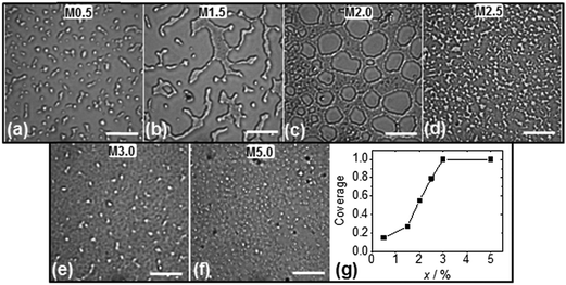
Prior to studying spin coated microgel and microgel/P3HT films it was important to determine the concentration of microgel particles required to achieve full coverage of the glass substrate. Optical micrographs were obtained for spin coated microgel films using concentrations in the range of 0.5 to 5.0% (Fig. 2). As the microgel concentration increased the microgel islands (Fig. 2a) became larger (Fig. 2b) and interconnected (Fig. 2c and d). The morphology apparent in Fig. 2b is similar to that reported by Wellert et al. for their spin coated ethylene glycol based microgels.15 Once the microgel concentration reached 3.0% gaps were no longer apparent (Fig. 2e and f). (The white points in Fig. 2e and f were isolated (small) microgel clusters on top of the microgel monolayer.) The fractional surface coverage of the substrate was calculated from the optical images and are shown in Fig. 2g. It follows that x = 3.0% corresponded to the critical microgel concentration for full coverage. A large area SEM image of the M3.0 film (which covers an area of about 100 × 100 μm2) is shown in Fig. S1 (ESI†) and confirms that complete coverage occurred. Continuous macroscopic microgel particle films could be prepared using x > 3.0%. A demonstration that a coherent film was prepared can be seen in Fig. S2 (ESI†) where an optical micrograph for a scratched M3.0 film shows intact fragments. The latter observation implies that the polystyrene chains of neighbouring microgel particles had interpenetrated. The interpenetration of microgels at surfaces and interfaces is a controversial topic. However, recent reports have indicated that the phenomenon is widespread.35,36 We propose that the absence of significant electrostatic repulsion between the microgel particles aided interpenetration of the peripheral chains during solvent evaporation.
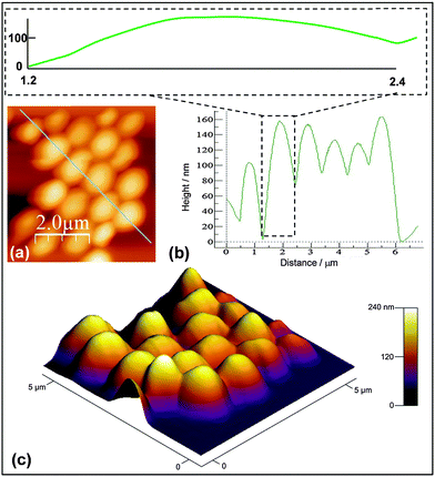
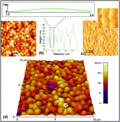
To enable the height of the flattened microgel particles to be estimated an AFM tapping mode image and line profile were obtained for M0.5 (Fig. 3a and b). The average peak-to-trough height from the line profile was ∼130 nm. The inset of Fig. 3b shows a line profile for a representative particle with the height and distance drawn at the same scale. These data confirm that the microgel particles flattened considerably. A perspective image (Fig. 3c) shows that all the particles had a flattened morphology. The aspect ratio for the microgel particles (=lateral diameter divided by particle height) was ∼10. This value is similar to that reported for poly(NIPAM-AA) microgels.10 Deposited viscoelastic vinylacetate-co-ethylene polymer particles have also shown comparable aspect ratios to that reported here.37 The value is much smaller than the value of at least 300 reported for highly deformable “self-crosslinked” poly(N-isopropylacrylamide)-based microgel particles.28 However, the latter particles were specially designed to have ultralow crosslinking. Our data show that the flattening of deposited solvent-swellable microgels is comparable to that reported for water-swellable microgels.
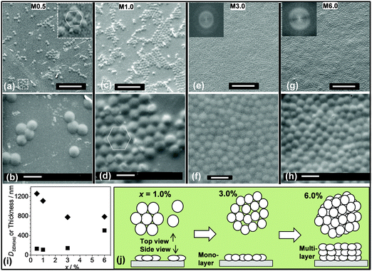
To further probe the microgel particle film (Mx) morphologies they were examined using SEM as a function of x (Fig. 4a–h). These images confirm that the coverage increased with x and reached a monolayer at x = 3.0% (cf.Fig. 2g). The particle clusters present for M0.5 (Fig. 4a and b) and M1.0 (Fig. 4c and d) formed 2D crystals. For all of the 2D crystals in this work the average number of nearest neighbours for each particle was six and hexagonal close packing was evident. Hexagonally close packed particles are highlighted in Fig. 4a and d. Fig. S3 (ESI†) shows a large area SEM image for the M1.0 film and many islands of 2D crystals can be seen. However, for the M3.0 (Fig. 4e and f) and M6.0 (Fig. 4g and h) film the particles were not able to form large 2D crystals. (The FFT insets of Fig. 4e and g show that the films were not ordered into an array.) Thus, 2D crystals were formed for the spin coated when the particle concentration used was less than 3.0%. Higher magnification SEM images for the Mx films (second row of Fig. 2) enabled estimates of the deposited microgel particle diameters. The values are plotted as a function of x in Fig. 4i (black diamonds). These values are much larger than the diameter for isolated (spherical) particles dispersed from water (DSEM(w) = 635 nm). Hence, the microgel particles had flattened for all of the films. The DSEM(eb) values for the M0.5 and M1.0 film from Fig. 4i can also be compared to the DSEM(eb) value of 895 nm obtained from microgel particles dried in air on SEM stubs (Fig. 1e and f). It follows that spin coating introduced an additional contribution to flattening for the microgel particles, presumably as a result of the increased shear present.38
The thicknesses of the M1.0, M3.0 and M6.0 films were measured using profilometry (Fig. 4i, black squares). The thickness values measured for the M1.0 and M3.0 films of 110 and 143 nm, respectively, are not significantly different to the height of 130 nm measured by AFM for M0.5 (the latter data point is also shown in Fig. 4i). By contrast, the thickness for the M6.0 film (505 nm) was much larger. The DSEM(eb) values for M3.0 and M6.0 were similar (Fig. 4i) and appear to have reached plateau values. Therefore, the much greater film thickness for M6.0 at near constant DSEM(eb) value is attributed to multi-layer formation. Restrictions of lateral particle flattening were imposed by neighbouring particles when x > 3.0% which compressed the swollen particles during deposition. For M6.0 multilayer formation occurred because microgel particle swelling pressure reached a critical value and further compression was more energetically demanding than multilayer formation. If it is assumed that the flattened microgel particle thickness was constant (∼130 nm) the M6.0 film would have contained ∼4 microgel layers.
The changes of particle packing and morphology with x are depicted in Fig. 4j. For x < 3.0% (less than full coverage) monolayer islands of nanocrystals formed and became larger as x increased. Once x reached 3.0% complete coverage occurred and the microgel particles became kinetically trapped without the opportunity to rearrange to produce extensive 2D crystalline arrays. The high number-density of neighbours decreased the average microgel diameter. With greater x values (e.g., 6.0) the particles formed multilayers. It is noted that spin coating differs considerably from the centrifugal method developed by Lyon et al. for increasing particle concentration whilst preserving monolayer coverage.14 With spin coating the particles are not as strongly forced to retain a monolayer geometry and are subjected to less lateral compression. Consequently, they can form multiple layers at lower energetic cost. Spin coating is well suited to forming large area films and is scalable.
Morphologies of spin-coated microgel/P3HT composite films
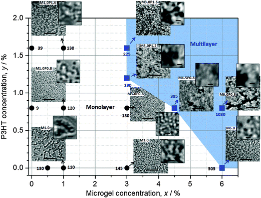
We next investigated microgel/P3HT films. Whilst P3HT was soluble in ethylbenzene heated to 70 °C at concentrations of 0.8–3.2%, the solubility decreased as the temperature approached room temperature and thermoreversible gels formed. A similar observation was reported elsewhere39 for P3HT dissolved in xylene, which is an isomer of ethylbenzene. Here, mixed dispersions of microgel and P3HT were compatible at 70 °C without evidence of aggregation. Rapid spin coating of heated mixtures (Scheme 1) provided macroscopically smooth composite films which strongly absorbed light. Fig. 5 shows the compositions of the mixed microgel/P3HT dispersions used to prepare the MxPy composite films. Optical micrographs for the films are also shown. In addition, the average film thickness is shown next to each symbol. The optical micrographs for the composite films investigated showed that they were heterogeneous at the micrometre length scale and microgel particles can be seen for many of the images, especially for the films with lower x and y values.It can be seen from the micrographs that the composites that exhibited the most uniform dispersion of microgel particles were M1.0P0.8 and M3.0P0.8. The composite films with the highest y values (e.g., M1.0P1.6 and M3.0P1.6) exhibited micrometre scale phase separation with particle aggregates and darker, particle-free, regions evident. The composite films containing the highest x values (M4.5P0.8 and M6.0P0.8) exhibited evidence of sheets of microgel particles that were separated by darker P3HT-rich regions. The composite films in the top right hand corner of the diagram (blue region) had the greatest heterogeneity of the microgel and P3HT-rich regions. It follows that the best mixing of the two phases at the micrometre-scale was achieved using the intermediate concentrations of microgel and P3HT (M1.0P0.8 and M3.0P0.8). We will show later that these films also had monolayers of microgel particles.
In order to obtain topographical morphological information AFM data were obtained for the M3.0P0.8 film. Fig. 6a shows that a nanoparticle aggregates were present between the microgel particles (indicated by an arrow). The line profile for the film (Fig. 6b) shows that the height of the microgel particles above the baseline was ∼70 nm. This value is much lower than the microgel height of about 130 nm determined from Fig. 3b for the M0.5 system (which did not contain P3HT). A maximum sketched with the same height and width scale (inset of Fig. 6b) shows that the maxima were broader compared to the M0.5 particles (inset of Fig. 3b). We propose that the valleys for M3.0P0.8 were the top of deposited P3HT. We term the latter nanometre-sized regions between the microgel particles as P3HT nanodomains. Consequently, the height of 70 nm is proposed to correspond to that of the microgel particles above the surrounding P3HT nanodomains. If it were assumed that the flattened microgel particle thickness was ∼130 nm an estimate of the thickness for the P3HT nanodomains for M3.0P0.8 would be ∼60 nm. The latter value is about a factor of 7 greater than the thickness measured for a control P0.8 film (9 nm). Clearly, the presence of the microgel particles strongly affected the deposition of the P3HT phase during spin coating.
The presence of the P3HT strongly affected the ability of the films to withstand solvent washing. Indeed, it was very difficult to remove microgel particles from the composite films when they were dipped and sonicated in ethylbenzene (a good solvent for polystyrene and P3HT). Fig. S4 (ESI†) shows images of M3.0P1.6 and M3.0 films after ethylbenzene soaking and sonication. Even when the ethylbenzene was heated to 70 °C and sonicated for extended periods, the microgel particles remained on the surface. However, the M3.0 film exhibited substantial loss of particles when dipped in ethylbenzene with minimal sonication. P3HT appeared to behave as a cement and locked the microgel in place. This proposal is supported by a phase image for the M3.0P0.8 film (Fig. 6c) which shows that the P3HT nanodomains filled gaps between the microgel particles. The perspective image shown in Fig. 6d shows clearly that the P3HT nanodomains filled gaps between the microgel particles across a wide region of the film.
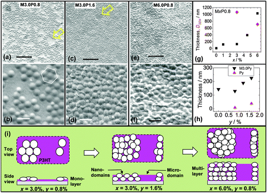
To determine the effect of P3HT concentration (y) on the nanometre-scale morphology of the microgel/P3HT films an SEM study was conducted. Fig. 7a and b show images for the M3.0P0.8 film. The microgel particles were dispersed as islands that had crystalline packing. The extensive crystallinity within the microgel islands and can also be seen from Fig. S5 (ESI†), which shows a large area SEM image (∼100 × 100 μm2). Furthermore, the surface coverage by the microgel particles was less than unity for M3.0P0.8. Both of these features contrast strongly to the situation for M3.0, which did not show extended crystallinity (Fig. S1, ESI†) and had a coverage of unity (above). These differences are due to P3HT diluting the microgel particles for M3.0P0.8. It is important to note that the presence of crystalline islands (Fig. 4b and Fig. S5, ESI†) shows that P3HT did not interfere with microgel self-assembly. This observation confirms that P3HT did not cause aggregation of the microgel particles. Formation of 2D crystals requires microgel particle rearrangement and this may occur on an experimentally meaningful timescale when the inter-particle attraction is comparable to kT. Photoactive composites with crystalline particles embedded within them could enable new applications as photonic or optoelectronic materials.
SEM images were also obtained for composite films with larger x and y values. Images are shown for M3.0P1.6 (Fig. 7c and d) and M6.0P0.8 (Fig. 7e and f). These images reveal the presence of two P3HT environments. There were P3HT nanodomains (between the microgel particles) as well as microdomains (between islands of microgel particles). The latter are identified with arrows in Fig. 7a and c. The values for DSEM(eb) and the film thickness are shown as a function of x in Fig. 7g. The DSEM(eb) value decreased from 1070 nm for M3.0P0.8 to 715 nm for M6.0P0.8. This trend is due to an increase in the number of nearest neighbours for each microgel particle. The film thicknesses were about 120 nm for M1.0P0.8 and M3.0P0.8 which is close to 130 nm (height for M0.5). This finding strongly suggests that microgel monolayers were present. By contrast the thickness increased significantly for M4.5P0.8 and M6.0P0.8 (Fig. 7g). The thickness values for these films (>400 nm) were much larger than the height of the microgel particles. Accordingly, it can be concluded that M4.5P0.8 and M6.0P0.8 contained microgel multilayers. This trend is the same as that observed for the pure microgel films (Fig. 4i).
The effect of y on the morphology and thickness was investigated using the M3.0Py series. The DSEM(eb) value for the M3.0P1.6 film was 805 nm, which was much smaller than the value for M3.0P0.8 (1070 nm). This result indicates restriction of microgel particle lateral spreading occurred. Presumably, an increase in P3HT solution viscosity occurred in regions between microgel particles upon cooling and this opposed microgel spreading. Whilst osmotic deswelling of polystyrene microgel particles by added non-adsorbed polymer is known2 the P3HT concentrations used for the mixed dispersions were low (maximum of 1.6%) and this effect is not considered to have been significant. These results suggest that added linear polymer concentration can be used to tune the extent of microgel spreading within composite films, which is a new observation. The film thickness data (Fig. 7h) show that the thickness of the M3.0Py films increased for y > 1.2. This thickness increase was significantly larger than from a linear combination of the thicknesses of each component (pure P3HT and microgel) and is most likely due to multilayer formation. The film thicknesses (189–225 nm) may indicate some inter-digitation of flattened microgel particles.
From consideration of the data presented above depictions of the different composite morphologies are presented (Fig. 7i). It is proposed that addition of P3HT affected the film morphology by preventing the microgel particles from coming into close contact. Monolayer films with P3HT nanodomains and microdomains were present for M3.0P0.8. Furthermore, both P3HT domain types persisted when the multilayers state were formed. The morphological roles of P3HT were to (partially) oppose microgel spreading and increase the (average) separation between particles.
The structural order of the P3HT phase at the Angstrom scale was probed by WAXD using out-of-plane diffraction for M3.0P1.6 and P1.6 films (Fig. S6a, ESI†). Data were also obtained for a M3.0 film as a control. Peaks were evident for M3.0P1.6 and P1.6 at 2θ = 5.5°, 10.5° and 23.0°, which are assigned to primary (100), secondary (200) and face-to-face (010) stacking, respectively.20,40 The (100) peak originates from lamellae oriented perpendicular to the film plane20 and was pronounced for M3.0P1.6 and P1.6. These data suggest that stacking of P3HT lamellae perpendicular to the film plane occurred for both the M3.0P1.6 composite and P1.6. It follows that the microgel particles enabled normal P3HT packing to be maintained on the Angstrom scale for the composites.
The electrical conductivities for several microgel/P3HT films were also measured using the four-point probe method (Fig. S6b, ESI†). The conductivities, and hence charge transport abilities, for M3.0P0.8, M3.0P1.2 and M3.0P1.6 were similar to that for pure P3HT (i.e., the P1.6 film). These data suggest that charge transport pathways for the M3.0Py films, which are proposed to have involved inter-connected P3HT nanodomains and microdomains, were not significantly restricted by the microgel particles. The data support the view that the P3HT phase surrounded the microgel particles in the composite films. It follows that P3HT acted as electrically conducting cement for the microgel particles within the composites.
An important question concerning the extent of microgel particle flattening within the composite films is what the extent of P3HT penetration within the microgel particles is in the dispersed state prior to spin coating. It is reasonable to expect that microgel particles containing P3HT would be less likely to flatten upon spin coating compared to pure microgel particles. Whether or not penetration occurs will depend in large part on the mesh size of the microgel particles and the hydrodynamic diameter of the P3HT chains in ethylbenzene at 70 °C. The number-average molecular weight range of P3HT used here was 25![[thin space (1/6-em)]](https://www.rsc.org/images/entities/char_2009.gif) 000–35
000–35![[thin space (1/6-em)]](https://www.rsc.org/images/entities/char_2009.gif) 000 g mol−1 based on supplier information (see Experimental section). These values may be considered as linear polystyrene equivalent molecular weights. An earlier study of microgels with the same composition as used here showed16 that osmotic deswelling (due to exclusion of linear polystyrene chains) occurred when the number-average molecular weight of linear polystyrene exceeded 5450 g mol−1. Consequently, the latter gives an approximate exclusion polystyrene molecular weight. Therefore, there is good reason to believe that the P3HT chains used here were too large to penetrate the interior of the swollen microgel particles in this study prior to film formation and were excluded.
000 g mol−1 based on supplier information (see Experimental section). These values may be considered as linear polystyrene equivalent molecular weights. An earlier study of microgels with the same composition as used here showed16 that osmotic deswelling (due to exclusion of linear polystyrene chains) occurred when the number-average molecular weight of linear polystyrene exceeded 5450 g mol−1. Consequently, the latter gives an approximate exclusion polystyrene molecular weight. Therefore, there is good reason to believe that the P3HT chains used here were too large to penetrate the interior of the swollen microgel particles in this study prior to film formation and were excluded.
Light absorption properties of microgel/P3HT composite films
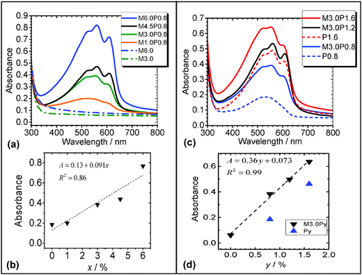
In order to probe the light absorption behaviour of the composite films UV-visible spectra were measured as a function of x for MxP0.8 (Fig. 8a). The spectra show strong absorption from P3HT vibronic bands in the 500 to 600 nm region.41 There was also a contribution to the absorbance values in the 300 to 500 nm region from light scattering due to the microgel particles. The latter is evident by comparison of the spectra for the pure M3.0 and M6.0 films (Fig. 8a). The absorbance at 525 nm was plotted as a function of x (Fig. 8b) and the absorbance appears to be proportional to x. Interestingly, as x increased the absorbance for the composite films increased by a factor of 3 whilst the weight fraction of P3HT in the composites decreased by a factor of 8 (i.e., from a P3HT weight fraction of 1.0 for P0.8 to 0.12 for M6.0P0.8). Thus, diluting P3HT with microgel particles increased the absorbance from the P3HT component for these composites. Introducing P3HT in phase-separated domains may strongly enhance light scattering since the bulk of the film now displays spatial refractive index variation on a length scale comparable to the wavelength of visible light. Additionally, the MxP0.8 films (x = 4.5 and 6.0) had multiple layers (discussed above) which increased the composite pathlength. However, the latter must be tensioned against the decrease in P3HT weight fraction (above). We propose that enhanced light scattering contributed to an increased efficiency of P3HT light absorption. By enhanced light scattering we mean the scattering of light from microgel particles caused an increased pathlength in the P3HT phase. The variation of x is a potentially useful method for tuning (and increasing) light absorption from P3HT within microgel/P3HT composite films. This approach should also apply for other conjugated polymer/microgel composites and could provide a useful method for increasing light absorption whilst minimising material use of conjugated polymers, which can be very expensive.The effect of y on the light absorption properties of M3.0Py films was also studied (Fig. 8c). The vibronic bands for P3HT were most pronounced for M3.0P1.2 and M3.0P1.6. The absorbance at 525 nm increased linearly with y for the M3.0Py films (Fig. 8d). The absorbance for the composite films was consistently higher than those for the, respective, pure Py films. The linear dependence of absorbance with y for the composites most likely originates from an increase in the P3HT thickness within the nanodomains and microdomains. These data show that tuneability of light absorption by composite microgel/P3HT films can also be achieved using y. It is remarkable that the absorption of light by these new composite films can be independently increased in a tuneable manner by increasing the content of either component (microgel or P3HT).
The absorbance data from Fig. 8b and d were plotted as a function of film thickness (from Fig. 7g and h) to probe the relationship between these two quantities (see Fig. 9). Caution must be applied when considering these data because the absorbance and thickness values are dominated by different parts of the composite, i.e., P3HT and the microgel particles, respectively. The data for both the M3.0Py and MxP0.8 films appear to show linear behaviour although the gradients differ. It is expected that the absorbance of photoactive film (e.g., P3HT composite) will be proportional to the film thickness based on Beer's law42 and also experimental data reported for P3HT-based films.43 Here, the gradient for the M3.0Py films is highest because P3HT addition is the most direct method for increasing the P3HT pathlength. The gradient is lowest for the MxP0.8 systems because the absorbance of the P3HT phase increased due to the indirect (secondary) influence of the microgel particles. The latter increased the effective pathlength via enhanced light scattering as well as the overall film thickness of the P3HT phase due to multilayer formation.
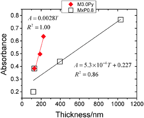 | ||
| Fig. 9 Dependence of microgel/P3HT film absorbance on film thickness. The thickness and absorbance data have been taken from, respectively, Fig. 7g and h as well as Fig. 8b and d. | ||
Conclusions
In this study we investigated the morphology of spin coated films of pure polystyrene microgel and also microgel/P3HT composites. In contrast to other work,10,15,28 the present films were prepared using solvent-swellable microgels. The deposited microgel particles were flattened with aspect ratios of about 10. In this regard, the polystyrene microgels behave in a similar manner to that reported for water-swellable microgels. For the pure microgel films the critical concentration at which full monolayer overage occurred was 3.0%. At higher concentrations multilayer films were produced. The pure microgel films and composite films contained microgel particle islands that were crystalline when the microgels were present as monolayers. The formation of the crystalline islands is likely to be general for spin coated films and composites prepared from solvent-swellable microgels. The microgel/P3HT composites were photoactive and electrically conducting. P3HT was shown to behave as an electrically conducting cement and increased the robustness of the composite when immersed in ethylbenzene. The microgel/P3HT films strongly absorbed light and this benefited from enhanced light scattering from the microgel particles within the matrix. Moreover, the absorbance for the composite films was tuneable and increased linearly both with microgel or P3HT concentration. For future studies solvents that dissolve both P3HT and polystyrene at room temperature should simplify film deposition and one candidate is chloroform. There is good reason to expect the results of this study will apply to other organic-swellable microgel/conjugated polymer composites. Highly ordered microgel/conjugated polymer composites which are also electrically conducting may provide new opportunities for future optoelectronic applications. For example, a microgel-based route is potentially available for hybrid polymer solar cell construction.44 This approach is possible because (a) polymer solar cells with good efficiencies have been prepared in the presence of polystyrene,19 (b) polystyrene microgel particles have been fully infiltrated with CdSe nanocrystals using microgel particle mesh size control4 and (c) the film thicknesses for the flattened microgel particles in this work are within the range used for hybrid polymer solar cells.45 Applications as photonic materials may also be possible if the extent of ordering can be increased in order to allow precise control over optical band gaps.Acknowledgements
BRS and POB would like to thank the EPSRC for funding this work.References
- J. A. Bonham, M. A. Faers and J. S. van Duijneveldt, Soft Matter, 2014, 10, 9384–9398 RSC.
- B. R. Saunders and B. Vincent, Adv. Colloid Interface Sci., 1999, 80, 25 CrossRef.
- T. Hoare and R. Pelton, Curr. Opin. Colloid Interface Sci., 2008, 13, 413–428 CrossRef CAS PubMed.
- M. Bradley, N. Bruno and B. Vincent, Langmuir, 2005, 21, 4 Search PubMed.
- J. Kleinen, A. Klee and W. Richtering, Langmuir, 2010, 26, 11258–11265 CrossRef CAS PubMed.
- E. S. M. Lee, B. Shuter, J. Chan, M. S. K. Chong, J. Ding, S.-H. Teoh, O. Beuf, A. Briguet, K. C. Tam, M. Choolani and S.-C. Wang, Biomaterials, 2010, 31, 3296–3306 CrossRef CAS PubMed.
- Y. Guan and Y. Zhang, Soft Matter, 2011, 7, 6375–6384 RSC.
- P. Bradna, P. Stern, Q. Quadrat and J. Snuparek, Colloid Polym. Sci., 1995, 273, 324 CAS.
- L. A. Lyon and A. Fernandez-Nieves, Annu. Rev. Phys. Chem., 2012, 63, 25–43 CrossRef CAS PubMed.
- S. Schmidt, H. Motschmann, T. Hellweg and R. von Klitzing, Polymer, 2008, 49, 749–756 CrossRef CAS PubMed.
- M. J. Serpe and L. A. Lyon, Chem. Mater., 2004, 16, 4373–4380 CrossRef CAS.
- C. D. Sorrell, M. C. D. Carter and M. J. Serpe, Adv. Funct. Mater., 2011, 21, 425–433 CrossRef CAS PubMed.
- C. D. Sorrell and L. A. Lyon, J. Phys. Chem. B, 2007, 111, 4060–4066 CrossRef CAS PubMed.
- A. B. South, R. E. Whitmire, A. J. Garcia and L. A. Lyon, ACS Appl. Mater. Interfaces, 2009, 12, 2747–2754 Search PubMed.
- S. Wellert, D. Kesal, S. Schon, R. von Klitzing and K. Gawlitza, Langmuir, 2015, 31, 2202–2210 CrossRef CAS PubMed.
- B. R. Saunders and B. Vincent, Colloid Polym. Sci., 1997, 275, 9 CAS.
- J. Zhou, G. Wang, M. Marquez and Z. Hu, Soft Matter, 2009, 5, 820 RSC.
- T. P. Bigioni, X.-M. Lin, T. T. Nguyen, E. I. Corwin, T. A. Witten and H. M. Jaeger, Nat. Mater., 2006, 5, 265–270 CrossRef CAS PubMed.
- T. A. Ferenczi, C. Muller, D. D. Bradley, P. Smith, J. Nelson and N. Stingelin, Adv. Mater., 2011, 23, 4093–4097 CrossRef CAS PubMed.
- Y. Kim, S. Cook, S. M. Tuladhar, S. A. Choulis, J. Nelson, J. R. Durrant, D. D. C. Bradley, M. Giles, I. McCulloch, C.-S. Ha and M. Ree, Nat. Mater., 2006, 5, 197–203 CrossRef CAS PubMed.
- F. Panzer, M. Sommer, H. Bässler, M. Thelakkat and A. Köhler, Macromolecules, 2015, 48, 1543–1553 CrossRef CAS.
- J. Clarke and B. Vincent, J. Chem. Soc., Faraday Trans. 1, 1981, 77, 13 RSC.
- J. W. Goodwin, R. H. Ottewill, R. Pelton, G. Vianello and D. E. Yates, Br. Polym. J., 1978, 10, 173–180 CrossRef CAS PubMed.
- B. R. Saunders, N. Laajam, E. Daly, S. Teow, X. Hu and R. Stepto, Adv. Colloid Interface Sci., 2009, 147–148, 251–262 CrossRef CAS PubMed.
- J. Keddie and A. F. Routh, Fundamentals of latex film formation, Springer Science & Business Media, 2010 Search PubMed.
- Y. Huang, W. Wen, S. Mukherjee, H. Ade, E. J. Kramer and G. C. Bazan, Adv. Mater., 2014, 26, 4168–4172 CrossRef CAS PubMed.
- Y. Xia, X. He, M. Cao, C. Chen, H. Xu, F. Pan and J. R. Lu, Biomacromolecules, 2013, 14, 3615–3625 CrossRef CAS PubMed.
- X. Hu and L. A. Lyon, ACS Macro Lett., 2015, 4, 302–307 CrossRef CAS.
- V. Nerapusri, J. L. Keddie, B. Vincent and I. A. Bushnak, Langmuir, 2006, 22, 6 CrossRef PubMed.
- A. A. Feiler, P. T. Davies and B. Vincent, Soft Matter, 2011, 7, 6660–6670 RSC.
- M. Richter, M. Hunnenmorder and R. V. Klitzing, Colloid Polym. Sci., 2014, 292, 2439–2452 CAS.
- S. Wellert, Y. Hertle, M. Richter, M. Medebach, D. Magerl, W. Wang, B. Demé, A. Radulescu, P. Müller-Buschbaum, T. Hellweg and R. von Klitzing, Langmuir, 2014, 30, 7168–7176 CrossRef CAS PubMed.
- E. C. Onyiriuka, C. B. Moore, F. P. Fehlner, N. J. Binkowski, D. Salamida, T. J. King and J. G. Couillard, Surf. Interface Anal., 1998, 26, 270–277 CrossRef CAS.
- P. A. Kralchevsky and N. D. Denkov, Curr. Opin. Colloid Interface Sci., 2001, 6, 383–401 CrossRef CAS.
- W. Wang, A. H. Milani, L. Carney, J. Yan, Z. Cui, S. Thaiboonrod and B. R. Saunders, Chem. Commun., 2015, 51, 3854–3857 RSC.
- W. Richtering, Langmuir, 2012, 28, 17218–17229 CrossRef CAS PubMed.
- J. K. Dreyer, T. Nylander, O. J. Karlsson and L. Piculell, ACS Appl. Mater. Interfaces, 2011, 3, 167–176 CAS.
- D. T. W. Toolan, S. Fujii, S. J. Ebbens, Y. Nakamura and J. R. Howse, Soft Matter, 2014, 10, 9 CrossRef.
- S. Malik, T. Jana and A. K. Nandi, Macromolecules, 2001, 34, 275–282 CrossRef CAS.
- H. Sirringhaus, P. J. Brown, R. H. Friend, M. M. Nielsen, K. Bechgaard, B. M. W. Langeveld-Voss, A. J. H. Spiering, R. A. J. Janssen, E. W. Meijer, P. Herwig and D. M. de Leeuw, Nature, 1999, 401, 685–688 CrossRef CAS.
- C. Hellmann, N. D. Treat, A. D. Scaccabarozzi, J. Razzell Hollis, F. D. Fleischli, J. H. Bannock, J. de Mello, J. J. Michels, J.-S. Kim and N. Stingelin, J. Polym. Chem. B, 2015, 53, 304–310 CrossRef CAS PubMed.
- J. Nelson, The physics of solar cells, Imperial College Press, London, 2007 Search PubMed.
- D. Vak, J. van Embden, W. W. H. Wong and S. Watkins, Appl. Phys. Lett., 2015, 106, 033302 CrossRef PubMed.
- J. Yan and B. R. Saunders, RSC Adv., 2014, 4, 29 Search PubMed.
- B. R. Saunders and M. L. Turner, Adv. Colloid Interface Sci., 2008, 138, 1–23 CrossRef CAS PubMed.
Footnote |
| † Electronic supplementary information (ESI) available. See DOI: 10.1039/c5sm01618e |
| This journal is © The Royal Society of Chemistry 2015 |

