
 Open Access Article
 This Open Access Article is licensed under a Creative Commons Attribution-Non Commercial 3.0 Unported Licence
The swim force as a body force
Wen
Yan
 *a and
John F.
Brady
b
*a and
John F.
Brady
b
aDepartment of Mechanical & Civil Engineering, California Institute of Technology, Pasadena, CA 91125, USA. E-mail: wyan@caltech.edu
bDivision of Chemistry & Chemical Engineering and Engineering & Applied Science, California Institute of Technology, Pasadena, CA 91125, USA. E-mail: jfbrady@caltech.edu
First published on 2nd July 2015
Abstract
Net (as opposed to random) motion of active matter results from an average swim (or propulsive) force. It is shown that the average swim force acts like a body force – an internal body force. As a result, the particle-pressure exerted on a container wall is the sum of the swim pressure [Takatori et al., Phys. Rev. Lett., 2014, 113, 028103] and the ‘weight’ of the active particles. A continuum description is possible when variations occur on scales larger than the run length of the active particles and gives a Boltzmann-like distribution from a balance of the swim force and the swim pressure. Active particles may also display ‘action at a distance’ and accumulate adjacent to (or be depleted from) a boundary without any external forces. In the momentum balance for the suspension – the mixture of active particles plus fluid – only external body forces appear.
1 Introduction
The soft matter community has proposed several theoretical approaches to investigate the behavior of active matter systems. Thermodynamic-type models, such as the ϕ4 field theory,1 motility-induced-phase-separation,2,3 and density functional theory,4 treat active matter as a single substance and try to fit it into the classical framework of the states of matter. For example, the dilute-dense coexistence of active matter can be formulated as a first-order gas–liquid phase transition.5,6Despite its success in explaining some states of active soft matter, thermodynamic models are not sufficient when the detailed dynamics, structure and deformation are of interest, especially when external perturbations are applied. In these situations, Fokker–Planck or Smoluchowski equations are often used as they directly relate the individual swimmer's Langevin equation to the position-orientation (x,q) phase space probability density P(x,q,t), which gives all the detailed information of interest. Active matter under an external force,7 polarization,8 and rectification9 have been investigated with this approach. When the detailed chemical propulsion mechanism or hydrodynamic interaction are considered, P(x,q,t) can be solved together with the conservation equation for chemical species concentration c(x,t) or the flow field u(x,t), allowing detailed knowledge of the dynamics, such as the system's stability.10
The Smoluchowski approach, however, is not able to treat concentrated systems where particle–particle interactions are important, even for the simplest excluded volume interactions. For dense active matter, simulation is the standard approach. Active Brownian dynamics simulations of as many as 107 particles have been reported in order to investigate phase behavior.11 A few simulations of active matter with hydrodynamic interactions have also been reported.12,13
Even with a wealth of simulation data, some fundamental questions remain. For example, how does one predict the force exerted on a boundary by (dense) active matter? Simulations give an a posterior determination of the force,14,15 while the Smoluchowski approach can be used but only for dilute systems when particle–particle interactions are ignored.16
For conventional atomic or molecular matter, at the particle level there are Newton's laws of motion and their phase-space equivalent the Liouville equation. For active colloids, the corresponding particle-level equations are the Langevin equation and the Smoluchowski equation. Thermodynamics, whether for conventional or active matter, does not permit any spatial or temporal variation in properties and thus, while powerful, has its limitations. To bridge the gap between the detailed particle and the thermodynamic levels, conventional matter employs continuum mechanics which applies out of equilibrium for slow spatial and temporal variations. The purpose of this work is to investigate and develop an analogous continuum mechanics description for active matter.
In conventional matter, forces at the particle level do not manifest themselves in the continuum momentum balance unless they are external body forces. Interparticle forces contribute to the continuum stress, but do not act as net forces at the continuum level. For active matter the situation is more complex and more interesting. As we show, the propulsive swim force acting at the particle level that causes particles to move is part of the hydrodynamic force the particles exert on the fluid, and thus when considering the momentum balance for the suspension – the mixture of particles plus fluid – there is no net hydrodynamic force and thus no net swim force acting on the mixture; only external body forces appear. However, the suspension is a two-phase mixture of active particles and fluid and in the continuum momentum balance for the particle phase we show that a net swim force appears directly and acts as an internal body force. This net swim force is crucial for describing the dynamics of active matter and for computing forces exerted on boundaries.
The swim force plays a pivotal role in the swim pressure,5 whose introduction provided a new approach to understanding the behavior of active matter. Active Brownian particles (ABPs) that separate into dilute and dense regions are now understood as a ‘gas–liquid’ coexistence. The decrease in the swim pressure with concentration destabilizes the system resulting in phase separation.5,6 The swim pressure is analogous to the osmotic pressure of a chemical solute or of passive Brownian particles and is the pressure needed to confine the active particles. In the dilute limit the “ideal gas” swim pressure is Πswim = nζU02τR/6 (in 3D), where n is the number density of active particles, ζ is their drag coefficient, U0 is the swim speed, and τR is their reorientation time.5
While the swim pressure can be understood solely in terms of this entropic confinement pressure and is independent of the size of the swimmers,5 micromechanically, the swim stress is given by the moment of the swim force 〈σswim〉 = −n〈xFswim〉, where Fswim = ζU0q, with q the orientation vector of the swimmer and x its position. The position is simply 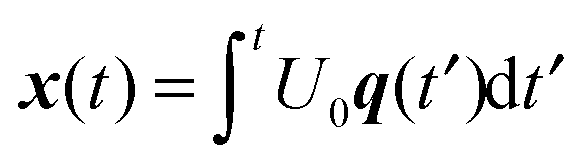 , and thus,
 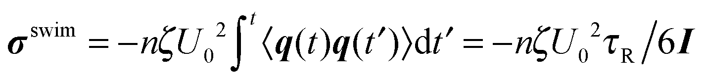 (for times t ≫τR), arising from the random reorientation of the swimmer: 〈q(t)q(t′)〉 = (I/3)exp{−2(t − t′)/τR}. The ‘moment arm’ for the swim stress is the swimmer's run length,
 ![[small script l]](https://www.rsc.org/images/entities/char_e146.gif) = U0τR.
= U0τR.
The micromechanical definition of the swim stress thus involves the swim force, which leads to questions about the ‘force-free’ nature of low-Reynolds number swimming. Furthermore, the swim stress sparked some recent discussion17 about whether it is a true stress – is it equal to the force per unit area on the bounding walls? – especially when the dynamics give rise to polar order: a non-zero average orientation of the particles, 〈q〉 ≠ 0.
In this paper we first show the origin and definition of the swim force that is consistent with the notion of ‘force-free’ motion. We then establish the global force (or momentum) balance for active matter, focusing on the case when there is net polar order 〈q〉, which corresponds to an average swim force 〈Fswim〉. We show that in the momentum balance for the active particles, the average swim force acts just like a body force, with the result that the force/area exerted by active matter on a bounding wall is the sum of the swim pressure and the ‘weight’ of the active particles. Thus, the questions raised in Solon et al.18 are straightforwardly resolved and in a manner completely consistent with one's intuition about forces and pressures.
Further, we show that a sedimentation-like system is achieved for 〈Fswim〉 ≠ 0 without any external body force and a continuum Boltzmann distribution holds just as for passive Brownian particles in a gravitational field. Active particles may also accumulate adjacent to (or be depleted from) a boundary, for example in response to an external stimulus (chemical, light, etc.). The interesting aspect is that this accumulation (depletion) occurs without there being any external force acting on the particles; it is a true ‘action at a distance’.
Although an average swim force acting like a body force arises naturally from the particle-level dynamics, it is nevertheless surprising since, as mentioned before, it does not appear in the macroscopic momentum balance for the entire suspension, or mixture, of particles plus fluid.
2 The swim force
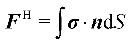
In self-propulsion at low Reynolds number by ‘force-free’ one means that there is no external force causing the body to move. The ‘internal’ forces that cause it to move arise from deformation of the body surface and are part of the total hydrodynamic force (and torque), which, from the linearity of Stokes flow, can be written as | (1) |
![[scr F, script letter F]](https://www.rsc.org/images/entities/char_e141.gif) H = (FH,LH), and similarly for the translational/rotational velocities:
H = (FH,LH), and similarly for the translational/rotational velocities: ![[scr U, script letter U]](https://www.rsc.org/images/entities/char_e534.gif) = (U,Ω). The hydrodynamic tensors R, RE, etc. are functions of the body geometry only and couple the force to the velocity, to the ‘squirming set’ Es(t), Bs(t), etc., which characterize the ‘slip’ velocity at the body surface. A derivation of (1) can be found in Appendix A.
= (U,Ω). The hydrodynamic tensors R, RE, etc. are functions of the body geometry only and couple the force to the velocity, to the ‘squirming set’ Es(t), Bs(t), etc., which characterize the ‘slip’ velocity at the body surface. A derivation of (1) can be found in Appendix A.
In (1) the hydrodynamic force/torque is written as a sum of two terms: (i) the hydrodynamic drag drag and (ii) the propulsive or ‘swim’ force swim. Eqn (1) provides the definition of the swim force. That it is a real measurable force can be appreciated by recognizing that if one wanted to keep the swimmer from moving, say by trapping it with optical tweezers, the force/torque the trap would exert is precisely swim.
In addition to the hydrodynamic drag and swim force, active particles can also be subject to thermal Brownian motion (B = 2kBTRδ(t)), external forces such as buoyancy (ext), and interparticle forces, for example repulsive interactions to prevent overlap at finite concentrations (P).†
In the simplest model of active particles the hydrodynamic resistance tensor is an isotropic drag tensor RFU = ζI and the swim force is Fswim = ζU0q. This is the ‘Active Brownian Particle’ (ABP) model:
| 0 = −ζU + Fswim + FB + Fext + FP. | (2) |
In this paper we focus on the ABP model (eqn (2)), with both translational and rotational diffusion: DT, DR. The reorientation time is τR = 1/DR. The relative importance of advection by swimming to translational swim diffusion is given by the reorientation Péclet number5 PeR = U0a/(6Dswim) = a/U0τR, and is also the ratio of the particle size to the swimmer's run length.
3 The global force balance
Consider a very simple geometry where N swimmers are placed between two parallel walls separated by a distance L whose normals are along the z-direction as illustrated in Fig. 1. The walls are of large extent (infinite) and system can be taken to be periodic in the x- and y-directions. The walls are non-penetrating to swimmers but allow the solvent to pass through unimpeded – they are osmotic barriers. Each swimmer i experiences a wall force FWi when it ‘collides’ with a wall. The separation L between the walls is sufficiently large so that the swimmers are able to execute their random swim motion before colliding with the walls – the swimmer's size a and run length are both small compared to L.
 | ||
| Fig. 1 Active Brownian particles (ABPs) in a container of height L in the z-direction and periodic in the x- and y-directions. Each active particle experiences a swim force Fswim = ζU0q, with q(t) the direction of swimming. An external gravitational (Ĝ) and polarization (Ĥ) field may also be applied. The top and bottom boundaries do not allow the particles to escape (no flux), but the flow of fluid uf is unimpeded – they are osmotic barriers. The horizontal plane S(z) is the cross-section considered in global force balance (4). | ||
The global force balance is the sum over all swimmers of each individual Langevin eqn (2). At steady state  and
and
| 0 = NζU0〈q〉 + N〈Fext〉 + FWTop + FWBot, | (3) |
 ,
,  , and
, and 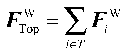 is the force on the top wall and involves only those particles interacting with that wall; a similar expression applies to the bottom wall. The Brownian and interparticle forces in (2) make no contribution to the global balance. Brownian forces, by definition, have zero average, while the interparticle forces are equal and opposite when two particles interact.
The net force on the walls is balanced by the total external body force acting on the particles within the volume plus the total average swim force. As far as the particles are concerned, an average swim force, 〈Fswim〉 = ζU0〈q〉, acts like just like a body force – an internal body force.
Now consider a control volume composed of the bottom wall and a horizontal plane at an arbitrary location z above the wall (cf.Fig. 1). The global force balance is
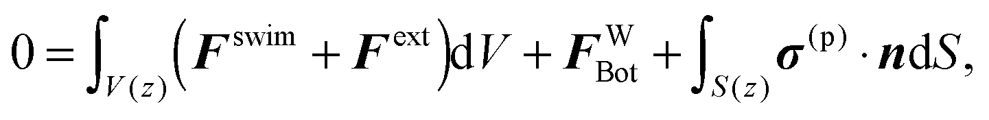 | (4) |
The surface S(z) is of large horizontal extent and therefore forms an average. If the variation in properties in the z-direction is slow on the scale of the particle size and/or run length, we may replace the surface stress with the particle-phase stress (at z) found by standard averaging of the microscale dynamics (2)viz.:
| 〈σ(p)〉 = −nkBTI − n〈x(Fswim)′〉 − n〈xFP〉, | (5) |
The z-component of the force balance in (4) is
 | (6) |
The effect of an external body force is well-known, and our derivation shows that an average swim force has the same effect. An average swim force could exist throughout the volume if the swimmers had a biased swimming, say due to a gradient in a stimulant (chemical, light, etc.), or it can arise from the boundary if the boundary were to promote a local orientational order.
Recently, Solon et al.18 derived the dilute limit expression for the wall pressure when an external torque is applied to each ABP that collides with the wall and found that ΠW depends on the form of the torque and therefore concluded that the swim pressure was ill-defined because, according to them, it depended on the nature of the wall and therefore was not a ‘true’ pressure. A nonzero torque induces a local 〈q〉 and therefore a nonzero swim force that must be included in the momentum balance. When this internal body force is included the global force balance (6) is satisfied and the swim pressure is indeed well-defined and independent of the boundaries.‡
4 Particle-phase momentum balance
Straightforward averaging of the microscale dynamics (2) results in the momentum balance for the particle phase:| 0 = −ζ〈jrel〉 + n〈Fswim〉 + n〈Fext〉 + ∇·〈σ(p)〉. | (7) |
 , and 〈u〉 = ϕ〈up〉 + (1 − ϕ)〈uf〉, with ϕ the volume fraction of particles and 〈uf〉 the average fluid velocity. Eqn (7) should apply locally at each ‘continuum point’, provided, as is standard in any continuum description, that there is a separation in scales with the macroscopic variations occurring on scales large compared to the microstructural length scales, importantly the run length = U0τR.
The momentum balance is used with the conservation of particle number density:
 | (8) |
The global force balance, (3) or (4), applies quite generally. In contrast, the continuum mechanics description, (7) and (8), requires a separation of scales between the microscale and the macroscale. While this separation is almost always true for passive Brownian particles, it requires careful examination for active matter, which we address in a future study.20
This completes the general discussion of the balance laws for active particles. We now demonstrate by a few illustrative examples that the average swim force acts as an internal body force and that the particle-phase momentum balance can accurately predict the concentration distributions and the forces on the walls.
5 The effect of internal and external body forces
5.1 Passive particles with gravity
We first consider a suspension of passive Brownian particles in a container as illustrated in Fig. 1. The swim force is zero, Fswim = 0, and, when dilute, the particle phase stress is simply the Brownian osmotic pressure 〈σ(p)〉 = −nkBTI; the collisional stress is O(n2). In the absence of gravity, the number density is uniform with height n(z) = n0 and the pressure on walls from (6) is the osmotic pressure ΠWBot = ΠWTop = n0kBT. With gravity, Fext = ΔρVpg; the buoyant force is given by the density difference Δρ = ρp − ρf times the volume of a particle VP and the acceleration of gravity g. The passive Brownian particles behave like an isothermal ideal gas in an external potential. At steady state there is no suspension velocity, 〈u〉 = 0, and the particles cannot escape the container, 〈jrel〉 = 0. From (7) in the dilute limit, n(z) has a Boltzmann distribution: n(z) = n0(L/LG)exp(−z/LG)/(1 − exp(−L/LG)), where LG = kBT/ΔρVpg is the sedimentation length. The pressures at the walls are ΠWBot = n(z = 0)kBT and ΠWTop = n(z = L)kBT, and their difference, ΠWBot − ΠWTop = n0ΔρVpgL, is the total buoyant weight of the particles in the container, in agreement with the global force balance (6).5.2 Active particles with gravity
We now examine a similar system of swimmers (ABPs) under gravity. Provided the gravitational forcing is not too strong no polar order will be induced by the no flux boundary at the bottom.7,9,20,21 In 2D for a dilute system the swim stress 〈σswim〉 = −nζU02τR/2I, and the total particle-phase stress is 〈σ(p)〉 = −n(kBT + ksTs)I, where we define the swimmer ‘activity’ ksTs ≡ ζU02τR/2. We perform active Brownian dynamics simulations in 2D with periodic boundary conditions in x and with a hard-particle potential when particles collide with each other or with either the top or bottom walls. Eqn (7) predicts a Boltzmann distribution: n(z) ∝ exp(−ΔρVpgz/(kBT + ksTs)) in the dilute limit, which is verified by simulation over a wide range of (dilute) area fractions ϕ0A = n0πa2, reorientation Péclet numbers PeR = a/(U0τR) ∈ (0.2,5.0), with or without translational diffusion, DT, and not too large gravity (ΔρVpg/(ζU0) < 0.2) as shown in Fig. 2. The global force balance (3) (and (6)) is verified by measurement of the force on the bottom wall in the simulations. | ||
| Fig. 2 Active particles with gravity. The local area fraction ϕAvs. height z/a in 2D. The symbols are simulation results and the solid lines are solutions to the continuum description (7). The log plot shows the same data as the linear plot. The dashed line corresponds to Boltzmann distribution n ∝ exp(−ΔρVpgz/(kBT + ksTs)) = exp(−0.04z/a); here ksTs = ζU02τR/2. N = 1000 particles are simulated in a square box of size 250a, and ϕ0A = 0.05. The box is periodic in the x-direction but confined by two no-flux walls located at z = 0 and z = L. The inset compares the force on the bottom wall from the particle–wall interactions in simulation with the buoyant weight of the particles. | ||
5.3 Orienting field to cancel gravity
From the global force balance (3), if 〈Fext〉 and 〈Fswim〉 cancel each other, then ΠWBot = ΠWTop and the continuum theory (7) predicts a uniform distribution of active particles. To test this, a non-zero 〈q〉 can be induced by an external polarization field as discussed by Takatori and Brady.8 An external field Ĥ applies a torque Ωcq × Ĥ to each swimmer and therefore the orientation vector q aligns in the field direction and diffuses around it through DR = 1/τR. The strength of the applied field is governed by the nondimensional field strength χR = ΩcτR. When χR → 0 the structure is isotropic, whereas when χR → ∞ all particles align and move in the direction Ĥ. Each swimmer has a net average velocity U0〈q〉(χR) due to the field, which can be canceled by Fext/ζ. With an orienting field the swim stress is anisotropic and given in ref. 8 in 3D and in Appendix B for 2D.Simulations were conducted in the same bounded geometry with Ĥ and gravity both perpendicular to the walls for a wide range of χR and Fext. The systems are homogeneous at steady state when gravity cancels the field (Fig. 3), and the wall pressures are equal as the global force balance (3) requires.
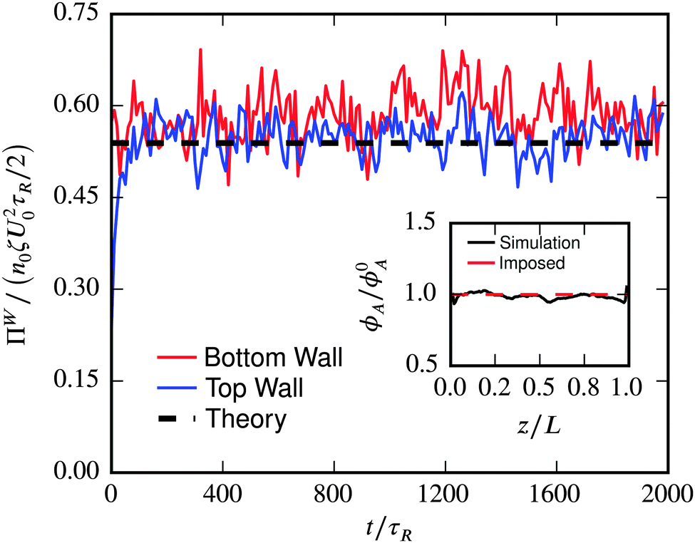 | ||
| Fig. 3 Orienting field to cancel gravity. The wall pressure vs. simulation time. Here, PeR = a/(U0τR) = 0.2, DT = 0, χR = ΩcτR = 1 and ΔρVPgτR/(ζa) = 2.23 = 〈qz〉U0τR/a. The inset shows the local area fraction ϕA as a function of height z, sampled by Voronoi cells. N = 1668 particles are simulated in a square box of size 512a at ϕ0A = 0.02. The data are averaged over 16 realizations. The system is periodic in the x-direction but confined by two no-flux walls located at z = 0 and z = L. The theory for the dilute limit and can be found in Appendix B. | ||
Theory8 predicts anisotropic stresses, and simulations were conducted at low area fraction (ϕA ≈ 0.02) without translational Brownian motion so that 〈σ(p)〉 = nksTs(![[small sigma, Greek, circumflex]](https://www.rsc.org/images/entities/i_char_e111.gif) swim∥ĤĤ + swim⊥(I − ĤĤ)), where swim∥ and swim⊥ are nondimensional functions of χR. To measure swim⊥, the Ĥ field is applied parallel to the walls (case A in Fig. 4); and for swim∥, Ĥ and the gravity field are perpendicular to the walls and cancel each other (case B in Fig. 4). Fig. 4 shows that the pressures on the walls determined in simulation agree with the theory.
swim∥ĤĤ + swim⊥(I − ĤĤ)), where swim∥ and swim⊥ are nondimensional functions of χR. To measure swim⊥, the Ĥ field is applied parallel to the walls (case A in Fig. 4); and for swim∥, Ĥ and the gravity field are perpendicular to the walls and cancel each other (case B in Fig. 4). Fig. 4 shows that the pressures on the walls determined in simulation agree with the theory.
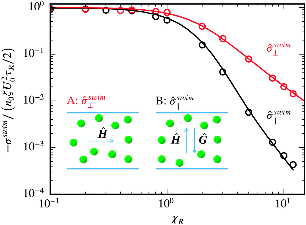 | ||
| Fig. 4 The anisotropic wall pressures compared with the dilute 2D theory (Appendix B). The circles are ABP simulations for PeR = a/(U0τR) = 0.2, DT = 0, ϕ0A = 0.02 and N = 1668. (A) for ⊥ the Ĥ field is applied in x-direction, whereas (B) for ∥ the Ĥ is applied in the z-direction and canceled by Fext. The square box of size 512a is periodic in x and confined by no-flux walls located at z = 0 and z = L. | ||
5.4 No gravity but with an orienting field
The resemblance of a swim force to an external body force is further illustrated by a system under a polarization field but no gravity. A constant downward Ĥ field gives a ‘sedimentation-like’ system with swimmers accumulating near the bottom wall as shown in Fig. 5. The measured bottom wall pressure is equal to the total ‘weight’ of the particles (divided by length Lx in 2D): N〈Fswim〉/Lx, as the global force balance (3) requires. Solving (7) with 〈Fswim〉 = ζU0〈q〉(χR) gives a Boltzmann distribution where the concentration is dilute with the ‘sedimentation length’ L∥ = (kBT + ksTsswim∥)/〈Fswim〉. The only difference compared to normal gravity is the anisotropic swim stress manifested by swim∥. As shown in Fig. 5 the calculated Boltzmann distribution n ∝ exp(−z/L∥) agrees with the simulations. In the simulations shown in Fig. 5, χR is adjusted according to (24), covering the range χR ∈ (0,3).
 | ||
| Fig. 5 No gravity but with an orienting field. The local area fraction ϕAvs. height z/a with the Ĥ field applied downward and Fext = 0. The symbols are simulation results and the solid line is the solution to the continuum description (7). The dashed line is a Boltzmann distribution ϕA ∝ exp{−〈Fswim〉z/(kBT + ksTs∥)} = exp(−0.04z/a), where ksTs = ζU02τR/2. N = 1000 particles are simulated in a square box of size 250a at ϕ0A = 0.05. The box is periodic in x but confined by no-flux walls at z = 0, L. The inset compares the force on the bottom wall from the particle–wall interactions in simulation with the ‘weight’ of the particles due to the swim force. | ||
Comparing the n(z) distributions and the ΠWBot of passive Brownian particles (Fig. 2) with swimmers under gravity (Fig. 5), one sees clearly that with a non-zero 〈q〉 swimmers behave as if acted upon by a body force. An internal body force Fint = ζU0〈q〉 = 〈Fswim〉 acts on each particle.
5.5 Depletion zone
Up to now we have considered the simplest cases in which polar order was induced by an orienting field homogeneously throughout the region between the two bounding walls. But this is not necessary. Suppose that the orienting field acts only over a length Δ < L. The effect of this field will lead to a depletion (or an accumulation) of active particles near the boundary depending on whether the field causes the particles to swim away from or towards the boundary. If the field is strong enough, there will be no particles contacting the wall and thus ΠWBot in (6) will be zero. For z > Δ there is no field and 〈Fswimz〉 = 0, while for z < Δ, n ≈ 0, and since the swim pressure far from the wall is Π(p) = nζU02τR/6, the global force balance (6) shows that there must be a transition region of thickness O( = U0τR) of high concentration of active particles near Δ. A particle swimming into the exclusion region z < Δ will, for a reorientation time, be unaware of the field and continue traveling at the swim speed. Fig. 6 demonstrates this behavior where a polarization field Ĥ is applied only in the region z < L/4. If the field is strong enough, χR > 1, there are no particles adjacent to the wall.
 | ||
| Fig. 6 A depletion zone induced by polarization. The local area fraction ϕAvs. height z/a with the Ĥ field applied upward in the region z < L/4 and Fext = 0. The solid lines are simulation. N = 1668 particles are simulated in a square box of size 512a at ϕ0A = 0.02. The box is periodic in x but confined by no-flux walls at z = 0, L. PeR = 0.2, DT = a2/τR. The inset checks the global force balance (3) and (4). | ||
This is a very interesting result in that there are no external forces acting on the particles, yet they move away from the wall. Passive particles cannot do this. By sensing their environment (light, chemical, etc. stimuli) active particles can adjust their internal swimming mechanisms and behave as if they experienced an actual repulsive (or attractive) force. Note that we modeled the orientation process as resulting from an external torque due to the field, but this is not necessary. All that is necessary is that the active particles adjust their swimming in response to their environment and they can do this completely internally by simply ‘choosing’ to swim towards or away from the stimulus. No external torque (or force) is needed. It is truly an ‘action at a distance’.
6 Suspension momentum balance
We have discussed the global force balance for the particle phase, but have not yet addressed the macroscopic momentum balance for entire suspension, or mixture, – the particles plus the fluid. For the mixture it must be appreciated that Fdrag and Fswim at the particle level are both parts of the hydrodynamic force FH exerted by the fluid on the particles (eqn (1)). The particles in turn exert the same force on the fluid, and thus only the external body force appears in the macroscopic momentum balance for the suspension:| 0 = n〈Fext〉 + ∇·〈σ〉. | (9) |
| 〈σ〉 = −〈pf〉I + 2η〈e〉 + 〈σ(p)〉, | (10) |
In the case where the orienting field gave rise to a depletion zone adjacent to the bottom wall, the suspension momentum balance shows that there will be a jump in the fluid pressure across the transition region from no particles to bulk behavior of magnitude 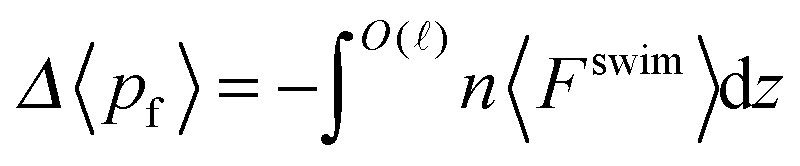 .
.
Computational continuum-scale studies of active suspensions10 employ the momentum balance (9).
7 Conclusions
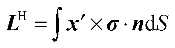
Interpreting an average swim force as a body force was done at two levels of description: (i) the global force balance (3), and (ii) the continuum description (7). The global force balance looks trivial because it involves only a simple sum of each swimmer's translational Langevin equation (2). The sum is performed without any knowledge of how swimmers interact with the boundary, how they orient in q-space, or how they are distributed in physical space. Also, no assumption of a ‘continuum’ is necessary and therefore (3) is quite general.With the continuum approach, however, the difficult problem of determining the deformation and stress of active matter is greatly simplified to solving (7) along with the conservation equation for the particle number density (8). Further, the constitutive equation for the active stress, 〈σ(p)〉(ϕ,PeR,…), is determined from homogeneous active matter systems6 and can then be used to predict the behavior in inhomogeneous situations, just as is done, for example, for the Navier–Stokes equations – the viscosity is measured in a uniform simple shear flow and then used in any flow geometry no matter how complex. When 〈Fswim〉, 〈Fext〉 are specified, the continuum equations are closed and the concentration and stress, ϕ(x,t) and 〈σ(p)〉(x,t), can be determined everywhere. The force on a boundary then follows from the standard continuum expression  .
.
The continuum description, which predicted the Boltzmann distributions for dilute systems, requires a separation of scales between the variation in macroscopic properties, such as n(z), etc., and the microscale, which for active matter is set by the swimmer's run length, = U0τR (and/or particle size a). In very dilute systems the run length can become large and if significant polar order is induced at a boundary, a continuum description may not be possible. In a future study20 we show how to accommodate these ‘non-continuum’ effects in the description of active matter.
As a final remark, we have considered average swim forces that are the result of polar order, 〈q〉 ≠ 0, as this is the most obvious case. However, what is important is that there is average swim force, 〈Fswim〉 ≠ 0, not that there is polar order. Recently we have shown6 that if there is a spatial variation in the intrinsic swim speed U0(x) or reorientation time τR(x), as might happen if the local fuel concentration varies, to leading order there is an average swim force: n〈Fswim〉 = −〈σswim〉·∇ln(U0τR). This average swim force must then appear in the global force balance (3) or (6) and in the continuum description (7).
Appendix A: the swim force of active matter
There is a recurring discussion in the literature about the nature and origin of the force causing self-propelled bodies to move at low Reynolds number. The discussion revolves about the notion that since self-propulsion is a ‘force-free’ motion, one cannot say that a self-propelled body experiences a Stokes drag. Or that the propulsive force can be written as a swim force Fswim = ζU0. And if it is, this swim force is not a ‘true’ force. However, this is a misunderstanding about what is force-free motion and the nature of hydrodynamics at low Reynolds numbers.The steady, non-accelerating motion of any body is force-free. At low Reynolds numbers Re = ρUa/η ≪ 1, where ρ is the density of the fluid, η is its viscosity, and U and a are the characteristic velocity and length scales of the motion, respectively, the acceleration of the fluid is negligible compared to the viscous and pressure forces and all motion is thus force-free. (We also specify that the inertia of the particle is negligible, which is characterized by the Stokes number St = ρp/ρ × Re ≪ 1, with ρp the particle density.) What is meant when one says that self-propulsion at low Reynolds number is force-free is that there is no external force causing the body to move. There are, however, internal forces that cause it to move.
In the simplest description of self propulsion, consider a body of fixed overall shape but whose surface can deform – a ‘squirmer’. A paramecium is the classic biological example and phoretic colloidal particles can also be modeled as being propelled by a local slip velocity at their surface.22,23 At a point x on the surface of a the body, the fluid velocity u(x) = U + Ω × (x − X) + us(x), where us is the ‘slip’ velocity, X is the body center, and U and Ω are the rigid-body translational and rotational motion of the body about its center. The slip velocity can be expanded in moments us(x′) = Es·x′ + Bs:(x′x′ − I(x′)2) + ⋯, where x′ = x − X, and the tensors Es(t), Bs(t), etc. are, in general, functions of time and are determined by the swimming gait. The linearity of low-Reynolds number or Stokes flow allows a familiar moment expansion24 of the total hydrodynamic force/torque H on the swimmer
| H = −R· − RE:Es − RB ⊙ Bs − ⋯, | (11) |
H = (FH,LH), and similarly for the translational/rotational velocities: = (U,Ω). The hydrodynamic resistance tensors R, RE, etc. are functions of the body geometry only and couple the force to the velocity, to the ‘squirming set’ Es(t), Bs(t), etc.
In the Stokes flow regime, the rigid body’s motion is overdamped and thus force-free: H + ext = 0, where ext is any external force such as gravity or an external torque. For a passive (i.e. non-swimming or non-active) body when ext = 0, H = 0 and there is no motion. For a swimmer when ext = 0, H = 0 is still true, but ≠ 0 in (11) – the drag, −R·, cancels the swimming part, −RE:Es − RB ⊙ Bs − ⋯. Indeed, we can define
| swim = −RE:Es − RB ⊙ Bs − ⋯, | (12) |
| drag = −R·, | (13) |
H = drag + swim = 0 gives| = R−1·swim. | (14) |
We have considered the simplest model for self-propulsion, namely a squirmer. However, as shown by Swan et al.26 the exact same structure applies for swimmers that propel by large deformations of their body shape – the hydrodynamic resistance tensors are now also functions of time but the definitions, (11)–(13), apply at each instant.
It is important to note that a nonzero swim force does not imply that the fluid velocity disturbance caused by the swimmer decays as 1/r as it would for a body with a nonzero hydrodynamic force. This is most clearly seen from the integral representation for the solution to the Stokes equations. The velocity field outside a particle in Stokes flow can be expanded in force moments to give
 | (15) |
 ,
,  , and the stresslet is given by
  , with σ the fluid stress tensor; there is a corresponding expression for the hydrodynamic quadrupole QH, etc.
Since the drag force drag balances the swim force there is no hydrodynamic force or torque on the swimmer: H = 0 (FH = 0, LH = 0), and the velocity disturbance decays at leading order as 1/r2 coming from the stresslet SH. If the slip velocity does not generate a stresslet, then the leading order velocity disturbance decays as 1/r3 corresponding to the quadrupole QH. And so on depending on the nature of the propulsive mechanism and the body geometry. There is no difficulty (or ambiguity) in speaking about a swim force and a drag force for a self-propelled body and the velocity disturbance generated by the swimming body decaying faster than 1/r. In fact, Blake22 and Ishikawa et al.27 expanded the hydrodynamic interactions between two squirmers in a series of surface radial and tangential velocity modes. These modes may cancel such that the velocity disturbance decays as 1/rn, which can be very fast for large n.
Even for a single particle, hydrodynamics can also generate a single particle contribution to the active stress σh ∼ nζU0a〈qq〉, which scales as nζU0a, as opposed to the swim stress that scales as nζU02τR. As discussed by Takatori et al.5 for fast swimmers (PeR → 0), σh/σswim ∼ U0a/(U02τR) = a/(U0τR) = PeR → 0.
Considering other forces that affect the motion of active particles, the overdamped Langevin equation of a set of swimmers can be written as,
| 0 = drag + swim + B + ext + P, | (16) |
B = 2kBTRδ(t) is a Brownian force with zero mean, ext is any external force, and P is a particle–particle interactive or collision force. The resistance tensors are now functions of both the individual swimmer body shape and the relative separation and orientation of all the swimmers, as is standard in Stokesian dynamics.
In the simplest case where the hydrodynamic interactions among the swimmers are neglected and only translational swimming is relevant, the hydrodynamic resistance tensor R can be simplified to an isotropic drag tensor ζI, so that Fdrag = −ζU, Fswim = ζU0q, and we have the ‘Active Brownian Particle’ (ABP) model eqn (2) of the main text. Here, q(t) is the orientation vector for the swimming direction and is subject to run-and-tumble motion or rotational Brownian diffusion, which are equivalent,19 and comes from the torque balance in (16). For a spherical swimmer, ζ = 6πηa and the swim force arises from the quadrupole squirming set Bs(t).
In this work we focus on this ABP model, with both translational (DT) and rotational (DR) diffusivity. In this case the time scale is set by 1/DR(= τR), and the reorientation Péclet number5 PeR = aDR/U0 = a/ controls how far the swimmer travels in one reorientation time – its run length = U0τR – compared to its size a. The ratio DT/(a2DR) controls the relative strength of translational Brownian diffusion and reorientational diffusion.
With swim defined in (12), the suspension stress28,29 in the absence of macroscopic shearing and external torques is:
| 〈σ〉 = −〈pf〉I + 〈σswim〉 + 〈σB〉 + 〈σP〉, | (17) |
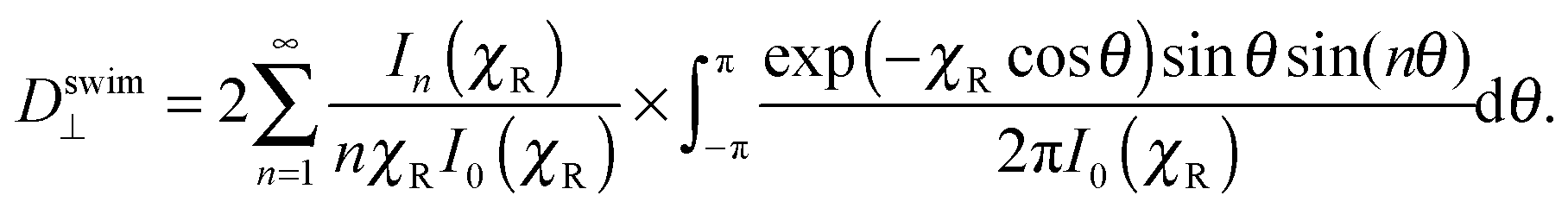
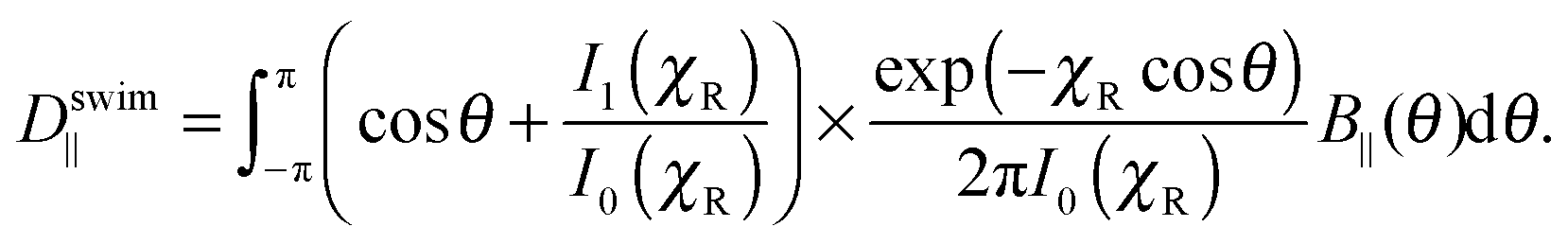
Appendix B: anisotropic stress under Ĥ field
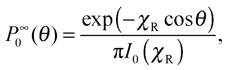
In this section we follow the convention of Frankel and Brenner30 to derive the anisotropic swim diffusivity Dswim and ideal gas swim stress σswim = −nζDswim. Similar methods have also been used in Zia and Brady31 and Takatori and Brady.8 In Frankel and Brenner's theory q is a local degree of freedom. For the swimmers considered here, q is the orientation vector of each swimmer. The steady state distribution, P∞0(q), is analytically solvable from the Langevin equation for q: | (18) |
 is the rotational Brownian motion characterized by DR.
The orientation-average velocity is defined as:
 | (19) |
 | (20) |
| ∇q·[uP∞0B − d·∇q(P∞0B)] = ΔUP∞0, | (21) |
 | (22) |
In a 2D system, q = (cos![[thin space (1/6-em)]](https://www.rsc.org/images/entities/char_2009.gif) θ,sinθ), and we define Ĥ = (0,1). The steady probability distribution P∞0(θ) is:
θ,sinθ), and we define Ĥ = (0,1). The steady probability distribution P∞0(θ) is:
 | (23) |
 | (24) |
With the mathematical expansion
 | (25) |
 | (26) |
 | (27) |
 | (28) |
 | (29) |
Appendix C: solution of continuum eqn (7)
The solution of the continuum eqn (7) at steady state requires a constitute law: 〈σ(p)〉(ϕ,U0,DT,τR). For the results in Fig. 2, the constitutive law can be found in the work of Takatori and Brady.6 For the results in Fig. 5, ksTs ≪ kBT since U0 is small, and therefore the stress for passive Brownian particles in 2D32 is used: 〈σ(p)〉(ϕ,U0,DT,τR) ∝ 1/(1 − ϕ)2.Acknowledgements
This work was supported by NSF Grant No. CBET 1437570.References
- R. Wittkowski, A. Tiribocchi, J. Stenhammar, R. J. Allen, D. Marenduzzo and M. E. Cates, Nat. Commun., 2014, 5, 4351 CrossRef CAS PubMed.
- J. Stenhammar, A. Tiribocchi, R. J. Allen, D. Marenduzzo and M. E. Cates, Phys. Rev. Lett., 2013, 111, 145702 CrossRef.
- M. E. Cates and J. Tailleur, Annu. Rev. Condens. Matter Phys., 2015, 6, 219–244 CrossRef CAS.
- A. M. Menzel and H. Löwen, Phys. Rev. Lett., 2013, 110, 055702 CrossRef.
- S. C. Takatori, W. Yan and J. F. Brady, Phys. Rev. Lett., 2014, 113, 028103 CrossRef CAS.
- S. C. Takatori and J. F. Brady, Phys. Rev. E: Stat., Nonlinear, Soft Matter Phys., 2015, 91, 032117 CrossRef CAS.
- M. Hennes, K. Wolff and H. Stark, Phys. Rev. Lett., 2014, 112, 238104 CrossRef.
- S. C. Takatori and J. F. Brady, Soft Matter, 2014, 10, 9433 RSC.
- J. Tailleur and M. E. Cates, Europhys. Lett., 2009, 86, 60002 CrossRef.
- E. Lushi, R. E. Goldstein and M. J. Shelley, Phys. Rev. E: Stat., Nonlinear, Soft Matter Phys., 2012, 86, 040902 CrossRef.
- J. Stenhammar, D. Marenduzzo, R. J. Allen and M. E. Cates, Soft Matter, 2014, 10, 1489 RSC.
- A. Lefauve and D. Saintillan, Phys. Rev. E: Stat., Nonlinear, Soft Matter Phys., 2014, 89, 021002 CrossRef.
- S. Li, H. Jiang and Z. Hou, Soft Matter, 2015 10.1039/C5SM00768B.
- X. Yang, M. L. Manning and M. C. Marchetti, Soft Matter, 2014, 10, 6477 RSC.
- S. A. Mallory, A. Šarić, C. Valeriani and A. Cacciuto, Phys. Rev. E: Stat., Nonlinear, Soft Matter Phys., 2014, 89, 052303 CrossRef CAS.
- Y. Fily, A. Baskaran and M. F. Hagan, Soft Matter, 2014, 10, 5609–5617 RSC.
- A. P. Solon, J. Stenhammar, R. Wittkowski, M. Kardar, Y. Kafri, M. E. Cates and J. Tailleur, Phys. Rev. Lett., 2015, 114, 198301 CrossRef.
- A. P. Solon, Y. Fily, A. Baskaran, M. E. Cates, Y. Kafri, M. Kardar and J. Tailleur, arXiv:cond-mat/1412.3952, 2014.
- M. E. Cates and J. Tailleur, Europhys. Lett., 2013, 101, 20010 CrossRef CAS.
- W. Yan and J. F. Brady, 2015, in preparation.
- M. Enculescu and H. Stark, Phys. Rev. Lett., 2011, 107, 058301 CrossRef.
- J. R. Blake, J. Fluid Mech., 1971, 46, 199–208 CrossRef.
- J. L. Anderson, Annu. Rev. Fluid Mech., 1989, 21, 61–99 CrossRef.
- S. Kim and S. J. Karrila, Microhydrodynamics: Principles and Selected Applications, Courier Corporation, 2005 Search PubMed.
- L. Durlofsky, J. F. Brady and G. Bossis, J. Fluid Mech., 1987, 180, 21–49 CrossRef CAS.
- J. W. Swan, J. F. Brady, R. S. Moore and ChE 174, Phys. Fluids, 2011, 23, 71901 CrossRef PubMed.
- T. Ishikawa, M. P. Simmonds and T. J. Pedley, J. Fluid Mech., 2006, 568, 119–160 CrossRef.
- G. K. Batchelor, J. Fluid Mech., 1970, 41, 545 CrossRef.
- J. F. Brady, J. Chem. Phys., 1993, 98, 3335–3341 CrossRef CAS PubMed.
- I. Frankel and H. Brenner, J. Fluid Mech., 1989, 204, 97–119 CrossRef CAS.
- R. N. Zia and J. F. Brady, J. Fluid Mech., 2010, 658, 188–210 CrossRef CAS.
- E. Helfand, H. L. Frisch and J. L. Lebowitz, J. Chem. Phys., 1961, 34, 1037–1042 CrossRef CAS PubMed.
Footnotes |
| † Hydrodynamic shear forces can also be present, but are not considered here; they enter in eqn (1). |
| ‡ The body force contribution is identical to the second term in eqn (7) of Solon et al.18 |
| § There may also be a hydrodynamic stresslet contribution that takes the form: n〈SH〉 ∝ nζU0a〈qq〉. |
| This journal is © The Royal Society of Chemistry 2015 |