 Open Access Article
Self-organized wrinkling patterns of a liquid crystalline polymer in surface wetting confinement†
Jun-Hee
Na‡
a,
Se-Um
Kim
a,
Youngjoo
Sohn
b and
Sin-Doo
Lee
*a
aSchool of Electrical Engineering, Seoul National University, 1 Gwanak-ro, Gwanak-Gu, Seoul 151-744, South Korea. E-mail: sidlee@plaza.snu.ac.kr
bDepartment of Anatomy, College of Korean Medicine, Kyung Hee University, Seoul 130-701, South Korea
First published on 30th April 2015
Abstract
Self-organized wrinkling patterns of a liquid crystalline polymer, dictated by the chemico-physically anisotropic nature of surface wettability, are demonstrated in confined geometries. The symmetry of the geometrical constraints of the confinement primarily governs the periodic wrinkling patterns of such a polymer in the wetting region. In a circular geometry, the number of the radial domains with multi-fold symmetries is linearly proportional to the radius of the confinement. The physical origin of the wrinkling process comes from the periodic bend–splay distortions through the relaxation of the curvature elasticity.
Periodic microstructures over a large area allow novel functionalities such as structural color and self-cleaning surfaces1–3 and lead to a wide range of applications from adaptive bioengineering4 and flexible electronics5 to adhesives.6 In constructing microstructures of diverse classes of materials, soft-lithography7 has been widely used but often involves inherent limitations to the applicability for non-planar surfaces and the pattern resolution predefined by the stamp. Recently, a variety of surface wrinkling and creasing patterns8–11 in thin films have attracted much attention from the viewpoints of the fundamental mechanism for the pattern formation as well as the advancement of bottom-up technology. It is known that the compression of a thin film on a compliant substrate provides a central mechanism for the spontaneous formation of highly ordered patterns above a certain (or critical) value for the onset of the elastic instability. The critical value of the stress is determined by the mechanical properties and the dimension of the film. The resultant patterns appear in a variety of morphologies and spatial configurations according to the difference in the applied stress state. To date, a number of different types of self-organized wrinkling have been reported.12–14 Some examples are surface wrinkling10,15 associated with osmotically driven swelling, anisotropic molecular ordering-based wrinkling in liquid crystal elastomers,16 and polymerization difference-induced surface instability.17 In such cases, patterns of microstructures are developed in many steps through random ordering or isotropic wrinkling into radial and circular shapes. For practical applications, the structural control of the functional materials in diverse configurations together with the simplicity in processing should be fully examined.
In this communication, we first describe the fundamental mechanism for self-organized wrinkling in ultraviolet (UV)-cured liquid crystalline polymer films and then demonstrate the single-step fabrication of wrinkling patterns with high fidelity in a well-controlled manner. The physical origin of wrinkling and the effect of geometrical constraints, such as the parallel and circular confinements, on wrinkling are presented. Our surface wetting geometry-based approach enables us to produce well-ordered microstructures through a simple process for self-organized wrinkling.
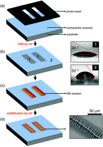
The step-by-step fabrication processes of anisotropic wrinkling patterns are described in Fig. 1(a)–(d). A hydrophobic fluorinated polymer (DS-1120, Harves Co., Ltd) of about 300 nm thick was first coated on a relatively hydrophilic glass substrate, which was cleaned in a piranha solution, as a commanding layer. It was then exposed to the UV light with the wavelength λ = 365 nm at the intensity of 100 mW cm−2 through a photo-mask with predefined patterns of chrome on a quartz plate so as to generate desired patterns as shown in Fig. 1(a). Using this selective wetting inscription (SWI), the patterns (denoted by 1) for wetting were precisely produced in the background dewetting region (denoted by 2) as in Fig. 1(b). Note that a quartz plate, not a soda lime glass substrate, was used for fabricating the photo-mask so that the UV light was barely absorbed and mostly reached at the commanding layer. The threshold for the photo-ablation4,18,19 of the commanding layer was found to be about 15 J cm−2.
A solution of reactive mesogens (RMs) (RMS03-001C, Merck Ltd) was then dip-coated at the speed of 20 mm min−1 as shown in Fig. 1(c). The RM solution was composed of 3 wt% of acrylate-based LC monomers with mesogenic groups including 4-(6-acryloyloxyhexyloxy)-benzoic acid (4-cyanophenyl ester), 4-(3-acryloyloxypropyloxy)-benzoic acid 2-methyl-1,4-phenylene ester, 4-(6-acryloyloxyhexyloxy)-benzoic acid-(4-methoxyphenylester), and 2-methyl-1,4-phenylene-bis[4-(6-acryloyloxyhexyloxy)benzoate] in the solvent of propylene glycol monomethyl ether acetate. In fact, the hydrophilic functional groups including acryl and ester in the RM favour to be wet in the hydrophilic region, meaning that the surface wettability leads directly to patterning capability. Depending on the dipping speed, the RM thickness was varied in the range of 0.1–5 μm. At the dipping speed of 20 mm min−1, the RM layer was about 0.3 μm thick. Upon dip-coating, only the hydrophilic region was covered with the RM solution. The RM droplet confined in the stripe pattern became gradually thin toward two confining boundaries, i.e., the thickness gradient was perpendicular to the boundaries, as shown in Fig. 1(c). The RM molecules were aligned along the direction normal to the droplet surface and the substrate surface. The sample with the RM pattern was baked for 1 min at 60 °C to remove the residual solvent. As shown in Fig. 1(d), the baked RM layer was finally irradiated to the UV light at the intensity of 100 mW cm−2 for 150 s to promote the self-organized wrinkling process through sequential cross-linking (see Fig. S1 in the ESI† for the dependence of the wrinkle formation on the UV irradiation). As clearly seen in the image of Fig. 1(d) observed using a scanning electron microscope (SEM), micro-fishbone structures, each of which having about a 0.5 μm-thick wrinkle ridge (see Fig. S2 in the ESI† for the image by atomic force microscopy), were developed in the wetting region after polymerization under the UV exposure. From the analytic relationship between the wavelength and the film thickness observed in geometrically confined polymers,20,21 it is expected that the period of the wrinkle depends on the ratio of the thickness of the fully cured, hard skin layer to that of the less cured, underlying elastic layer in view of elasticity. In other words, the relative thickness plays a primary role in the morphology of the wrinkles including the period and the amplitude.
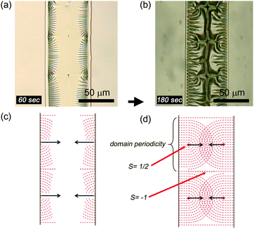
We first describe how the parallel confinement affects the growth and the self-organization of the wrinkles in the polymer film. The optical microscopic photographs in Fig. 2(a) and (b) show the wrinkle formation after 60 s and 180 s for the UV irradiation on the thermally treated RM film of 1.5 μm thick, respectively. Periodic splay–bend wrinkles were initially developed as shown in Fig. 2(a) and the domains of the wrinkles with the singularity of the strength of 1/2 and the disclination strength of −1, separating two adjacent domains, were further grown from two parallel boundaries as shown in Fig. 2(b) (see Fig. S3 in the ESI† for the birefringent patterns of the wrinkles observed using an optical polarizing microscope under crossed polarizers). In general, upon the UV exposure, photo-curable monomers experience cross-linking or polymerization in a depth-wise manner from the outer surface to the inner bulk by the curing treatment.4,17 This implies that in our case, the cross-linking in the RM layer confined between two boundaries is completed first in the edges as shown in Fig. 2(a) and later in the central region, meaning that the wrinkle formation proceeds from the edges toward the centre of the RM layer. As a consequence, the domain periodicity is formed perpendicular to the region boundary so as to laterally relax the stress built up during cross-linking. The outer layer of the monomers, being cured first, provides a solid, cross-linked skin which serves as a support for the stress in the inner bulk. The mechanical strength and the thickness of the skin depend on the intensity of the UV light in addition to the intrinsic material properties.
Since the skin becomes shrunk during polymerization,22 the in-plane tensile stress produced by the frustrated shrinkage on the substrate should be relaxed. This stress relaxation leads to the out-of-plane deformation of the skin in periodic wrinkles along the direction perpendicular to two parallel boundaries as shown in Fig. 2(a). The domains of the wrinkles, developed fully and merged together in the interior between the two boundaries, are seen in Fig. 2(b). This phenomenon shares common features of the LC domains although the length scale is very different.
Let us discuss the morphological characteristics of the wrinkling patterns in analogy to the defects and the disclinations observed in liquid crystals (LCs).23–25 In the LC case, the most probable director configuration is determined through the minimization of the total free energy with respect to the director field. Fig. 2(c) and (d) represent the schematic diagrams corresponding to Fig. 2(a) and (b) for the wrinkling patterns, respectively, where the wrinkling process is conceptually shown with the help of the patterns around the disclinations as in the continuum theory of the LC.22 The splay–bend patterns were simultaneously appeared in two parallel boundaries (the interfaces between hydrophilic and hydrophobic regions) and evolved toward the interior from the boundaries as shown in Fig. 2(c). Due to the mutual competition of the splay–bend distortions between adjacent domains in each boundary, periodic line defects with the strength of 1/2 were necessarily produced within the closed domains.26 Moreover, when the fronts of two domains grown from two opposite boundaries met together, the wrinkles became developed through the relief of the elastic strain and periodic domains with the disclination strength of −1 were produced in the central region as shown in Fig. 2(d). Note that the domain size of the wrinkles and the period (Λ) of the splay–bend distortions depend on the geometrical factors, such as the film thickness and the confined area, in addition to the material properties including the bend and splay elastic constants (for more details, see Fig. 3). A delicate interplay between the bulk elastic energy and the surface energy27 plays a significant role in the characteristics of the defects, particularly, in a thin solidified RM film as if the surface anchoring energy of the LC molecules dominates over the bulk elastic energy under a confined environment.28
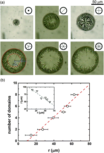
We now consider another type of the confinement with a closed topology. In contrast to the parallel, open geometry as in Fig. 2, the radial domains of the wrinkles were developed from the circumference of the circular wetting region with the radius of r, which represents a symmetric and closed topology, as shown in Fig. 3(a). Depending on the confinement dimension, the radial domains with multi-fold symmetries appeared by the orientational symmetry-breaking.29 Note that above a certain radius of the wetting region (r > 50 μm), essentially no further formation of the wrinkles was proceeded toward the centre, leaving out a rather uniform region within a circle of the radius of r′ as shown in Fig. 3(a). This implies that there exists a macroscopic characteristic length (ξ), which is related to the propagation of the splay–bend distortions, yielding the growth of the wrinkled domain, from the boundary to the centre of the wetting region. In other words, beyond the characteristic propagation length, the elastic strain resulting from the periodic splay–bend distortions becomes nearly relaxed to produce the uniform domain in the central region as observed for the cases of 5-, 6-, and 8-fold symmetries. From the measured values of r = 39.2 and 50.8 μm for 4- and 5-fold symmetries, respectively, in Fig. 3(a), ξ was estimated to be about 40 μm for the RM layer of 0.3 μm thick in our case. For r ≤ ξ, the wetting region was entirely covered with the periodic wrinkles whereas for r > ξ, an elastic strain-free uniform region was left out inside the circle of r′. This is the criterion for the formation of a ring-type region of the wrinkles (between r and r′) in the circular confinement. Let us analyse the pattern symmetry or the number of the radial domains as a function of r. As shown in Fig. 3(b), the number of the domains was found to be linearly proportional to r. This suggests that in principle, multi-fold symmetries are possible for all integers depending on the relative ratio of the periodicity Λ of the splay–bend distortions, described in Fig. 2, to the circumference 2πr in the circular confinement although 3- and 7-fold symmetries were not observed in the samples we studied. Another point is that the arc length (l) of each radial domain decreases with increasing r as shown in the inset of Fig. 3(b). From the viewpoint of the length scale, three key parameters of the radius r representing the confinement, the periodicity Λ, and the characteristic propagation length ξ of the splay–bend distortions come into play in determining the formation of a ring-type region of the wrinkles and the multi-fold symmetry of the periodic domains.
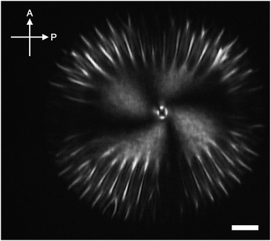
Finally, it is interesting to investigate the optical anisotropy of the wrinkled structure. Fig. 4 shows the birefringent patterns of the solidified RM film, observed under crossed polarizers, in the circularly confined geometry. The dark brushes that appeared typically in the Schlieren-type texture25 represent the local molecular orientations of the RM, which coincide with either the polarizer (P) or the analyser (A). The disclination associated with four brushes has the singularity with the strength of s = −1. The RM molecules were aligned radially toward the centre of the circular confinement along the direction either parallel or perpendicular to the tangent of the boundary. Clearly, the uniform alignment of the RM was achieved in the central region while the wrinkles were developed in the vicinity of the boundary. The birefringent wrinkles were profound in a rather thick (∼5 μm) layer of the RM but not in a relatively thin (>2 μm) layer because of no considerable optical anisotropy. The birefringent patterns of the wrinkles in a ring-type configuration (see Fig. S3 in the ESI†) have been used for developing an artificial iris.4
Summary
We demonstrated the self-organized wrinkling patterns, depending on the anisotropic nature of the surface wettability in the confined geometries, of the RM after solidification by the UV exposure. It was found that the multi-fold symmetries of the periodic wrinkling patterns in the solidified RM films were primarily dictated by the relative length scale among the confinement dimension such as the radius of the circular confinement, the periodicity of the splay–bend distortions of the RM material used, and the characteristic propagation length of the splay–bend distortions from the boundary toward the interior of the confined (or wetting) region. The self-organized wrinkling patterns with the optical anisotropy presented here may be useful for devising a new type of optical and/or biomimetic device with embedded periodic microstructures for applications such as in structural colours and metamaterials.Acknowledgements
This work was supported in part by the National Research Foundation (NRF) grant funded by the Korea government (MSIP) (No. 2011-0028422).Notes and references
- Z. Gu and H. Uetsuka, Angew. Chem., Int. Ed., 2003, 42, 894 CrossRef CAS PubMed.
- M. Toma, G. Loget and R. R. M. R. Corn, ACS Appl. Mater. Interfaces, 2014, 6, 11110 CAS.
- R. Blossey, Nat. Mater., 2003, 2, 301 CrossRef CAS PubMed.
- J.-H. Na, S. C. Park, Y. Sohn and S.-D. Lee, Biomaterials, 2013, 34, 3159 CrossRef CAS PubMed.
- Y.-T. Kim, S. Hwang, J.-H. Hong and S.-D. Lee, Appl. Phys. Lett., 2006, 89, 173506 CrossRef PubMed.
- A. K. Geim, S. V. Dubonos, I. V. Grigorieva, K. S. Novoselov, A. A. Zhukov and S. Y. Shapoval, Nat. Mater., 2003, 2, 461 CrossRef CAS PubMed.
- Y. Xia and G. Whitesides, Annu. Rev. Mater. Sci., 1998, 28, 153 CrossRef CAS.
- D. Khang, H. Jiang, Y. Huang and J. Rogers, Science, 2006, 311, 208 CrossRef CAS PubMed.
- T. Tanaka, S. Sun, Y. Hirokawa and S. Katayama, Nature, 1987, 325, 796 CrossRef CAS PubMed.
- J. Y. Chung, A. J. Nolte and C. M. Stafford, Adv. Mater., 2009, 21, 1358 CrossRef CAS PubMed.
- B. Li, Y.-P. Cao, X.-Q. Feng and H. Gao, Soft Matter, 2012, 8, 5728 RSC.
- Y. Ebata, A. B. Croll and A. J. Crosby, Soft Matter, 2012, 8, 9086 RSC.
- H. S. Kim and A. J. Crosby, Adv. Mater., 2011, 23, 4188 CrossRef CAS PubMed.
- D. Chandra and A. J. Crosby, Adv. Mater., 2011, 23, 3441 CrossRef CAS PubMed.
- C.-M. Chen, J. C. Reed and S. Yang, Soft Matter, 2013, 9, 11007 RSC.
- A. Agrawal, P. Luchette, P. Palffy-Muhoray, S. L. Biswal, W. G. Chapman and R. Verduzco, Soft Matter, 2012, 8, 7138 RSC.
- J. M. Torres, C. M. Stafford and B. D. Vogt, Soft Matter, 2012, 8, 5225 RSC.
- Y.-J. Na, S.-W. Lee, W. Choi, S.-J. Kim and S.-D. Lee, Adv. Mater., 2009, 21, 537 CrossRef CAS PubMed.
- A. Miotello and P. M. Ossi, Laser-Surface Interactions for New Materials Production, Springer, New York, 2010 Search PubMed.
- E. P. Chan, S. Kundu, Q. Lin and C. M. Stafford, ACS Appl. Mater. Interfaces, 2011, 3, 331 CAS.
- S. H. Kang, J.-H. Na, S. N. Moon, W. Il Lee, P. J. Yoo and S.-D. Lee, Langmuir, 2012, 28, 3576 CrossRef CAS PubMed.
- H. Lei, L. F. Francis, W. W. Gerberich and L. E. Scriven, AIChE J., 2002, 48, 437 CrossRef CAS PubMed.
- P. Kim, M. Abkarian and H. A. Stone, Nat. Mater., 2011, 10, 952 CrossRef CAS PubMed.
- F. C. Frank, Discuss. Faraday Soc., 1958, 25, 19 RSC.
- S. Zhang, E. M. Terentjev and A. M. Donald, J. Phys. Chem. B, 2005, 109, 13195 CrossRef CAS PubMed.
- G. S. Chandrasekhar, S. Ranganath, S. Chandrasekhar and G. S. Ranganath, Adv. Phys., 1986, 35, 507 CrossRef PubMed.
- P. G. DeGennes and J. Prost, The Physics of Liquid Crystals, Oxford University Press, New York, 1993 Search PubMed.
- J.-H. Na, J. Kim, Y. Choi and S.-D. Lee, Appl. Phys. Express, 2013, 6, 054102 CrossRef.
- W. Song, I. A. Kinloch and A. H. Windle, Science, 2003, 302, 1363 CrossRef CAS PubMed.
Footnotes |
| † Electronic supplementary information (ESI) available. See DOI: 10.1039/c5sm00694e |
| ‡ Present address: Department of Polymer Science and Engineering, University of Massachusetts Amherst, Amherst, Massachusetts 01003, USA. |
| This journal is © The Royal Society of Chemistry 2015 |


