
 Open Access Article
 This Open Access Article is licensed under a Creative Commons Attribution-Non Commercial 3.0 Unported Licence
A bioscaffolding strategy for hierarchical zeolites with a nanotube-trimodal network†
Guannan
Li
a,
Haibo
Huang
a,
Bowen
Yu
b,
Yun
Wang
a,
Jiawei
Tao
a,
Yingxu
Wei
b,
Shougui
Li
a,
Zhongmin
Liu
*b,
Yan
Xu
*a and
Ruren
Xu
a
aState Key Lab of Inorganic Synthesis and Preparative Chemistry, Jilin University, Changchun, 130012, China. E-mail: yanxu@jlu.edu.cn
bNational Engineering Laboratory for Methanol to Olefins, Dalian National Laboratory for Clean Energy, Dalian Institute of Chemical Physics, Dalian, 116023, China. E-mail: liuzm@dicp.ac.cn
First published on 23rd November 2015
Abstract
Hierarchical zeolite monoliths with multimodal porosity are of paramount importance as they open up new horizons for advanced applications. So far, hierarchical zeolites based on nanotube scaffolds have never been reported. Inspired by the organization of biominerals, we have developed a novel precursor scaffolding-solid phase crystallization strategy for hierarchical zeolites with a unique nanotube scaffolding architecture and nanotube-trimodal network, where biomolecular self-assembly (BSA) provides a scaffolding blueprint. By vapor-treating Sil-1 seeded precursor scaffolds, zeolite MFI nanotube scaffolds are self-generated, during which evolution phenomena such as segmented voids and solid bridges are observed, in agreement with the Kirkendall effect in a solid-phase crystallization system. The nanotube walls are made of intergrown single crystals rendering good mechanical stability. The inner diameter of the nanotube is tunable between 30 and 90 nm by varying the thickness of the precursor layers. Macropores enclosed by cross-linked nanotubes can be modulated by the choice of BSA. Narrow mesopores are formed by intergrown nanocrystals. Hierarchical ZSM-5 monoliths with nanotube (90 nm), micropore (0.55 nm), mesopore (2 nm) and macropore (700 nm) exhibit superior catalytic performance in the methanol-to-hydrocarbon (MTH) conversion compared to conventional ZSM-5. BSA remains intact after crystallization, allowing a higher level of organization and functionalization of the zeolite nanotube scaffolds. The current work may afford a versatile strategy for hierarchical zeolite monoliths with nanotube scaffolding architectures and a nanotube-multimodal network leading to self-supporting and active zeolite catalysts, and for applications beyond.
Introduction
Zeolites are microporous aluminosilicates of paramount importance in refineries and the petrochemical industry as size- and shape-selective catalysts due to their ordered micropores, acid strength and thermal/hydrothermal stability. But the sole presence of micropores with window openings smaller than 1 nm often causes restricted access and diffusion limitations that adversely affects their catalytic activity.1 Hierarchical zeolites that integrate the catalytic activity of zeolitic micropores with the transport advantage and the external reactivity of an auxiliary network of interconnected multimodal porosity have proved to be effective in both established and emerging applications.2 Hierarchical zeolites refer to zeolitic materials having at least two levels of porous hierarchy. Mesoporosity can be integrated by either a templating approach or by the leaching of framework atoms.3 Macroporosity is commonly generated by the replication of macroporous scaffolds, by evaporation of volatile products, and by aggregation of large zeolite crystals.4 These macropores are large and broad with pore openings in the micrometer scale, making them less useful for intended applications. Zeolite MFI crystals with intracrystalline macropores of 250–500 nm have recently been fabricated via the steam-assisted crystallization of mesoporous silica.5Transforming laboratory zeolites to industry catalysts is no easy task. Among other challenges, zeolite powders must be shaped with the aid of additives including binders. This is not only costly but causes a series of problems including dilution of the active species, diffusion limitation, pore blockage and inaccessibility to interior active sites.6 Depositing zeolite films on porous supports is further challenged by the easy loss of the zeolite films due to different thermal expansion coefficients. It is therefore of great importance to develop self-supporting hierarchical zeolite catalysts with desired porous hierarchy, good mass/heat transfer rates, low pressure drop and adequate mechanical strength.7 The concept of self-supporting zeolite catalysts was first demonstrated via a micro-macroporous Sil-1 with broad macropores centred at 500 μm using polyurethane foam.4a A series of landmark developments followed including a micro-mesoporous ZSM-5 using carbon aerogel,8 a micro-macroporous ZSM-5 with macropores of 3–8 μm by a silica gel transformation method,9 and a micro-macroporous Sil-1 with macropores of 10–50 μm by an ice templating method.10 The recent development of a self-supporting tetramodal ZSM-5 monolith containing two macropores (0.2–1.7 μm and 24–33 μm), intracrystalline mesopores centred at 53 nm and zeolitic micropores sets a new record in hierarchical zeolites research.11 ZSM-5 microtubes with trimodal porosity exhibit improved stability in the methanol-to-gasoline conversion.12 However, the ZSM-5 microtubes are discrete with an inner tube diameter of 2–4 μm, which are too large to be best utilized; besides, the microtube formation mechanism remains elusive. A supported hierarchical zeolite MFI displaying a trimodal network of zeolitic micropores (0.55 nm), intercrystalline mesopores (10 nm) and macropores (200–300 nm) yields superior performance in the methanol-to-olefin conversion compared to its conventional analogue.6a
Inspired by the organization of biominerals, we have developed a novel precursor scaffolding-solid phase crystallization strategy for hierarchical zeolites with a unique nanotube scaffolding architecture and nanotube-trimodal network using BSA as a scaffolding blueprint, which extends the regime of bioscaffold-mediated mineralization research.13 The strategy is conceptualized using bacterial cellulose (BC) aerogel, and the versatility is confirmed using chitosan (Ch) aerogel. The challenges for constructing stable zeolite nanotube scaffolds using BSA are overcome by first transforming BSA to a precursor scaffold both as a precursor source as well as a scaffolding template, followed by concurrent zeolite crystallization and nanotube formation via seeded solid phase crystallization. Zeolite nanotubes are self-generated, where BSA nanofibers are found running along the inner corridor of the nanotubes forming a wire-in-nanotube geometry. The evolution phenomena of zeolite nanotubes including ion diffusion pairs, segmented voids and solid bridges is in good agreement with the Kirkendall effect.14 Applying this strategy, ZNTS ZSM-5, TS-1 and Sil-1 have been obtained with narrow macropores (700 nm), narrow mesopores (2 nm), zeolitic micropores (0.55 nm) and uniform nanotubes with a tunable inner diameter between 30 and 90 nm by varying the thickness of precursor layer. The macroporosity can be modulated by the choice of BSA. The self-supporting ZNTS ZSM-5 catalyst exhibits a superior catalytic performance in the MTH conversion compared to conventional ZSM-5.
Results and discussion
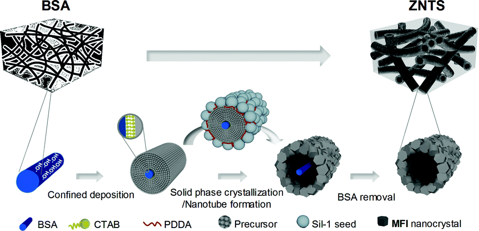
As illustrated in Scheme 1, the precursor scaffolding-solid phase crystallization strategy for ZNTS involves three principle steps: (1) formation of precursor scaffolds from BSA by confined deposition, (2) concurrent zeolite crystallization and nanotube formation, and (3) BSA removal. For easy illustration, the nanofabrication of ZNTS ZSM-5 using BC is discussed in detail below. Experimental details are provided in the ESI.† The precursor scaffold of BC@ASO is prepared from reaction mixtures with a typical composition of 42TEOS![[thin space (1/6-em)]](https://www.rsc.org/images/entities/char_2009.gif) :1ATSB:10NH3·H2O:11CTAB:178EtOH:0.6BC. The formation of BC@ASO is challenged by the following: (i) BC has an electronegative surface while aluminosilicates are polyanions, (ii) the polycondensation of TEOS is a rapid process that further facilitates the condensation of ATSB, and (iii) the diffusion of TEOS and ATSB is slow due to the percolating network of hydrogen-bonded BC nanofibers with internal voids filled with solvents (Fig. S1†). The confined deposition of aluminosilicates around BC is accomplished with the aid of a self-assembled layer of surfactant, CTAB. The compatibility between the diffusion rate and the rate of polycondensation of TEOS and ATSB is critical for deposition uniformity. This can be achieved by first soaking BC in ethanol containing a stoichiometric amount of TEOS, ATSB and CTAB at RT to allow thorough penetration, followed by the addition of ammonia at 0 °C to switch-on the polycondensation. BC@ASO has a smooth surface and uniform thickness with an average diameter of 200 nm (Fig. 1a). The diameter of BC@ASO can be tuned between 80 nm and 200 nm by varying the concentration of TEOS and ATSB, and the number of deposition cycles.
:1ATSB:10NH3·H2O:11CTAB:178EtOH:0.6BC. The formation of BC@ASO is challenged by the following: (i) BC has an electronegative surface while aluminosilicates are polyanions, (ii) the polycondensation of TEOS is a rapid process that further facilitates the condensation of ATSB, and (iii) the diffusion of TEOS and ATSB is slow due to the percolating network of hydrogen-bonded BC nanofibers with internal voids filled with solvents (Fig. S1†). The confined deposition of aluminosilicates around BC is accomplished with the aid of a self-assembled layer of surfactant, CTAB. The compatibility between the diffusion rate and the rate of polycondensation of TEOS and ATSB is critical for deposition uniformity. This can be achieved by first soaking BC in ethanol containing a stoichiometric amount of TEOS, ATSB and CTAB at RT to allow thorough penetration, followed by the addition of ammonia at 0 °C to switch-on the polycondensation. BC@ASO has a smooth surface and uniform thickness with an average diameter of 200 nm (Fig. 1a). The diameter of BC@ASO can be tuned between 80 nm and 200 nm by varying the concentration of TEOS and ATSB, and the number of deposition cycles.
 | ||
| Scheme 1 Nanofabrication of ZNTS by the precursor scaffolding-solid phase crystallization strategy. | ||
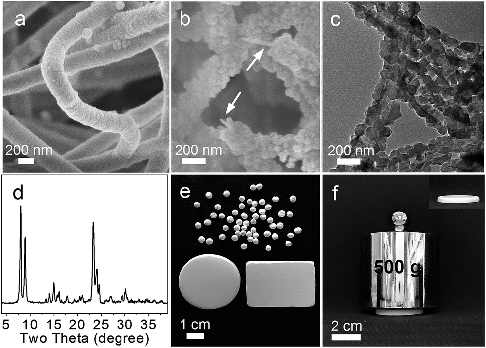 | ||
| Fig. 1 (a) SEM of BC@ASO precursor scaffold. (b) Cross-sectional view of BC@ZSM-5 by SEM showing a wire-in-nanotube geometry with BC (arrow) in the core of the nanotube. (c) Sideview of BC@ZSM-5 showing interconnected nanotube by TEM. (d) XRD pattern of ZNTS ZSM-5. (e) Photograph of ZNTS ZSM-5 showing tailorable geometry. (f) Photograph of ZNTS ZSM-5 showing negligible volume change after mechanical pressing. | ||
Concurrent zeolite crystallization and nanotube formation occur during the vapor treatment of the Sil-1 seeded BC@ASO under autoclaving conditions. Sil-1 seeds have uniform size with an average diameter of around 50 nm (Fig. S2a and S2b†). Seeding is driven by electrostatic interactions with an aid of a positive polyelectrolyte, PDDA.15 Partial seeding due to electrostatic repulsion can be overcome by using low molecular-weight PDDA together with small electrolytes such as NaCl.16 Seeding uniformity is crucial, and it can be accomplished by meticulous experimental design (Fig. S2c and S2d†). The seeded BC@ASO is transformed to BC@ZSM-5 nanotube scaffolds made of highly crystallized ZSM-5 nanocrystals (JCPDS 044-0002, ∼95%) after 72 h of the vapor treatment at 140 °C, where BC nanofibers are found running along the inner corridor of the nanotubes based on the SEM, TEM and FTIR analyses (Fig. 1b–d, S3†). Amorphous silica at 2θ = 20° and crystalline impurities are absent based on the XRD analysis (Fig. 1d). The challenges to preserve the scaffolding architecture can be overcome by treating the seeded precursor scaffolds using the vapor of 1EDA:12TEA:13H2O under autoclaving conditions, which is a modified steam-assisted crystallization method.17 White spongy monoliths of ZNTS ZSM-5 with tailorable geometry and adequate mechanical strength are recovered from BC@ZSM-5 by calcination at 550 °C (Fig. 1e and f, S3 and S4†).
ZNTS ZSM-5 has a nanotube scaffolding architecture based on cross-linked ZSM-5 nanotubes of uniform thickness (Fig. 2a–c). The nanotube wall is made of a single layer of intergrown nanocrystals of ZSM-5 with an approximate size of 70 nm (Fig. 2c). HRTEM shows uniform lattice fringes with a d-spacing of 0.99 nm corresponding to d020 of ZSM-5, suggesting the single crystal nature of the ZSM-5 nanocrystals (Fig. 2d). Adjacent nanocrystals of ZSM-5 intergrow based on the HRTEM analysis, rendering the nanotube high mechanical stability (Fig. 2d inset). The 29Si MAS NMR spectrum shows a prominent resonance at −110 ppm and shoulder peaks between −100 ppm and −105 ppm, featuring cross-linked Q4 units [Si(OSi)4], and Q3 units [(HO)Si(OSi)3, (AlO)Si(OSi)3] with a Q4/Q3 ratio of 1.95 (Fig. S5a†). No Q2 units are found in ZNTS ZSM-5. The sharp and symmetrical peak at 53 ppm on the 27Al MAS NMR spectrum indicates tetrahedral Al3+, and no octahedral Al3+ is detected (Fig. S5b†). ZNTS ZSM-5 with Si/Al ratio of 125 to ∞ has been obtained based on ICP.
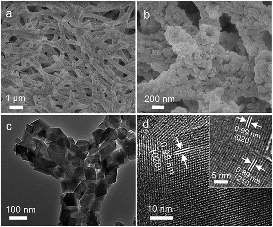 | ||
| Fig. 2 Characterizing ZNTS ZSM-5: (a) low magnification SEM showing nanotube scaffolding architecture. (b) High magnification SEM showing ZSM-5 nanotubes. (c) High magnification TEM showing nanotubes connectivity. (d) HRTEM showing the single crystal nature of ZSM-5. Inset: HRTEM showing the intergrowth between the adjacent nanocrystals of ZSM-5. | ||
The porosity of ZNTS ZSM-5 is examined by N2 sorption and Hg intrusion porosimetry measurements (Fig. 3a and b). It exhibits a typical type I isotherm with a sharp uptake at P/P0 < 0.1, revealing zeolitic micropores centred at 0.55 nm based on the Horvath–Kawazoe (HK) method (Fig. 3a, inset). The hysteresis at P/P0 = 0.50–0.75 is attributed to the capillary condensation in small mesopores. The H3 type hysteresis loop at P/P0 = 0.75–1.0 implies the presence of cylindrical mesovoids. The mesopore size distribution calculated by the BJH method from the adsorption branch reveals narrow mesopores centred at 2 nm formed by intergrown nanocrystals of ZSM-5 and mesovoids centred at 90 nm attributed to ZSM-5 nanotubes (Fig. 3a, inset). Narrow macropores are found between 400 and 900 nm based on the Hg intrusion porosimetry measurements (Fig. 3b, inset). The BET surface area is calculated to be 380 m2 g−1 and the total pore volume is 0.40 cm3 g−1 including 0.15 cm3 g−1 of micropores and 0.25 cm3 g−1 of mesopores. The nanotube scaffolding architecture is anisotropic based on the low magnification SEM (Fig. 3c and e), and the nanotube connectivity is evidenced by laser scanning confocal microscopy (LSCM) images of ZNTS ZSM-5 dyed with fluorescent rhodamine B (Fig. 3d and f). ZNTS ZSM-5 is hierarchically porous, where the nanotube-trimodal connectivity can be deduced from the unique construction and the greater BET surface area of ZNTS ZSM-5 than conventional ZSM-5.
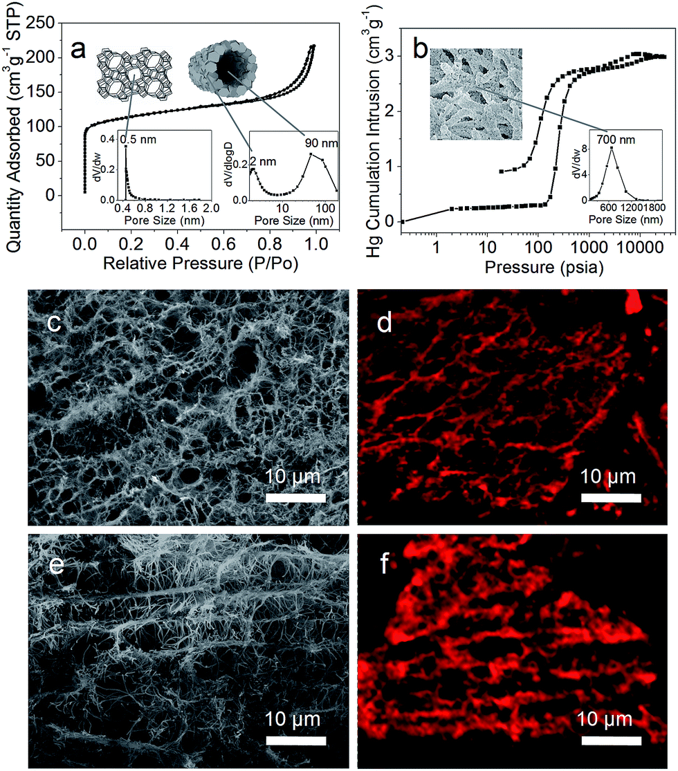 | ||
| Fig. 3 Characterizing the scaffolding architecture of ZNTS ZSM-5: (a) N2 sorption isotherm and micropore, mesopore and nanotube. (b) Hg intrusion porosimetry measurements and macropore profile. (c and e) Low magnification SEM and (d and f) LSCM images showing the anisotropic structure and the nanotubes connectivity, respectively. | ||
Notably, the macropores of ZNTS ZSM-5 downshift dramatically during the nanofabrication (Fig. S6a and S6b†). The greater outer diameter of the ZSM-5 nanotubes (∼300 nm) than the diameter of the BC@ASO fibers (∼200 nm) reduces the effective opening of the macropores (Fig. 2b and 1a). The deposition of aluminosilicates causes reassembly of the hydrogen-bonded network of the BC nanofibers, responsible for the downshift of the macropores of BC@ASO compared to BC. This is accompanied by the loss of crystalline order of BC due to cellulose regeneration in a strong alkaline medium (Fig. S6c†).18 The nanofabrication causes negligible volume change of the spongy monoliths from BC to ZNTS ZSM-5 (Fig. S6c† inset).
It is worth taking note that the inner diameter of the ZSM-5 nanotube is around 90 nm, which is significantly greater than the average diameter of BC being around 27 nm (Fig. 2b, 1b and S1†). It implies that the ZSM-5 nanotubes are generated by mechanisms beyond the simple replication of BC nanofibers. Hollow nanostructures can be generated due to different atomic diffusion rates of core and shell species, leading to void nucleation at the core/shell interface. The Kirkendall effect has been applied to explain the self-generation of hollow nanostructures of varying geometry and compositions.19 In a typical Kirkendall process, interim phenomena including segmented voids and solid bridges are usually found between core and shell, indicating a net outward diffusion and diffusion path, respectively.19b The average diameter of the Kirkendall hollow spheres is often smaller than the initial solid spheres.20
The evolution of the ZSM-5 nanotube is tracked to unravel the formation mechanism. The Sil-1 seeded BC@ASO are solid fibers with BC nanofibers in the core (Fig. 4a and b). After 6 h of vapor treatment, segmented voids are observed at the interface of the Sil-1 seeds and the amorphous aluminosilicates (Fig. 4c and d). As it proceeds, an interrupted tube with segmented voids and solid bridges become evident based on the high magnification TEM and SEM (Fig. 4e and f). The evolution of the ZSM-5 nanotube is accompanied by an increase in crystal dimensions as well as the crystallinity from ∼10% at 0 h to ∼95% at 72 h (Fig. 4a and g and S7a†), suggesting that crystallization drives the nanotube formation. The corresponding FTIR spectrum shows that the absorption band centred at 550 cm−1, associated with the asymmetric stretching mode of the double five-rings of the MFI structure, picks up intensity with time (Fig. S7b†). The optical density ratio of the 550 cm−1 band to the 455 cm−1 band at 72 h is around 0.73, close to that of the MFI structure, confirming the well crystallized ZSM-5 phase.
 | ||
| Fig. 4 Tracking the evolution of ZSM-5 nanotube using high magnification TEM and SEM: (a and b) 0 h. (c and d) 6 h. (e and f) 18 h. (g and h) 72 h. | ||
The average inner diameter of the nanotube (∼90 nm) is about 45% of the average diameter of BC@ASO (∼200 nm). This ratio is within the size ratio range of 40–70% reported for hollow nanoparticles evolved via the Kirkendall effect.20 To determine whether Al3+ ions have diffused into the Sil-1 seeds to replace Si4+ ions, XPS spectra were recorded on the untreated and the Ar-ion-sputtered nanocrystals of ZSM-5, and the Sil-1 seed. The presence of Al3+ ions on the surface and in the core of the ZSM-5 nanocrystals is indicated by the Al 2p3/2 peak at 74.5 eV with a slight decrease in intensity (Fig. S8†). It indicates that outbound diffusion of Al3+ ions coupled with inward diffusion of Si4+ ions takes place driven by ion-exchange, which contributes to the evolution of the ZSM-5 nanotubes.
The observations of ion diffusion pairs, segmented voids, solid bridges and the size reduction of the nanotube suggest that the evolution of the ZSM-5 nanotube is likely a manifestation of the Kirkendall effect in a solid phase crystallization system. The inner diameter of the ZSM-5 nanotube can be tuned between 30 and 90 nm by varying the thickness of the aluminosilicate layer (Fig. S9, S10 and Table S1†).
The feasibility of the current strategy is manifested by the successful fabrication of ZNTS TS-1 (Si/Ti ratio: 115 to ∞, crystallinity: ∼92%) and ZNTS Sil-1 (crystallinity: ∼97%) from the Sil-1 seeded precursor scaffolds of BC@TSO and BC@SO, respectively (Fig. S11a and S11b†). Ti4+ ions in ZNTS TS-1 are found exclusively in a tetrahedral environment based on the sole and strong absorption at 220 nm on the UV-vis spectrum, confirming that the amorphous precursor has transformed to the crystalline TS-1 phase (Fig. S11c†).21 The zeolitic micropores, textural mesopores, nanotubes and macropores are revealed by the sorption measurements (Fig. S12†). The signature nanotube scaffolding architecture is evidenced by the high magnification TEM and SEM (Fig. S12† insets). The micropore volumes of ZNTS TS-1 and ZNTS Sil-1 are similar to that of MFI, further confirming that the microporous structure of MFI is retained in the respective ZNTS (Table S2†). ZNTS TS-1 and ZNTS Sil-1 exhibit greater BET surface areas than the corresponding zeolite analogue,10,4b implying the nanotube-trimodal connectivity.
The versatility of the current strategy is further examined for the nanofabrication of ZNTS Sil-1 (Ch) using Ch aerogel (Fig. S13†). It exhibits the signature scaffolding architecture of ZNTS based on cross-linked nanotubes with tube walls made of intergrown nanocrystals of Sil-1 (Fig. S14†). The porous hierarchy is featured with zeolitic micropores (0.55 nm), textural mesopores (2 nm), nanotubes (inner diameter: 100 nm) and macropores (centre: 2 μm). Notably, the macropores of ZNTS Sil-1 (Ch) are larger than those of ZNTS Sil-1 from BC@SO (Fig. S14d and S12b2†), indicating that the macropore profile can be modulated by the choice of BSA. The textural properties of ZNTS Sil-1 (Ch) are summarized in Table S3.†
ZNTS ZSM-5 with a stable nanotube scaffolding architecture and nanotube-trimodal connectivity may prove to be a promising self-supporting zeolite catalyst. The MTH conversion was examined over the self-supporting monolith of ZNTS ZSM-5 in a fixed-bed stainless reactor. For comparison, a conventional ZSM-5 powder with similar dimensions, crystallinity and Si/Al ratio was used as a reference (Fig. S15a and S15b†).22 The NH3-TPD profiles of both ZNTS ZSM-5 and the conventional ZSM-5 show two peaks centred at 180 °C and 405 °C, corresponding to weak and strong acidity, respectively (Fig. S15c†). It indicates their very close acid strength and acid concentration.
Both of the ZSM-5 catalysts present approximately 100% of initial methanol conversion, however, the stability varies. The catalyst lifetime of ZNTS ZSM-5 is longer than that of the conventional ZSM-5 (Fig. S16a†). It is likely that the multiple interconnected micro-compartments, formed by the cross-linked ZSM-5 nanotubes with effective openings at the micrometer scale, enable easy diffusion of the methanol and hydrocarbon products. Under the same reactant-catalyst contact time, ZNTS ZSM-5 exhibits different product selectivity compared to the conventional ZSM-5 powder (Fig. S16b†). The relatively low selectivity for aromatics of ZNTS ZSM-5 indicates that the H-transfer reaction responsible for coke formation has been suppressed. This is further confirmed by the coke formation rate of 1.0 mg h−1 g−1 for ZNTS ZSM-5 and 1.5 mg h−1 g−1 for the conventional ZSM-5 based on the TG analysis of the used catalysts (Fig. S15d†). Given the similar catalyst dimensions, acidity, crystallinity and micropore volume of the two catalysts, we believe that the unique nanotube scaffolding architecture is the key reason for the excellent catalyst stability of ZNTS ZSM-5. The cause for coke formation is likely associated with the large nanocrystal size of ZSM-5 in ZNTS ZSM-5 resulting in a long diffusion path within zeolitic micropores, which needs to be further examined.
ZNTS ZSM-5 is a spongy monolith with an approximate density of 0.187 g cm−3 and porosity of 89%, which makes it a promising choice as a self-supporting hierarchical catalyst with transport advantages and added separation capability.
Conclusions
In summary, we have developed a novel precursor scaffolding-solid phase crystallization strategy for hierarchical zeolites with a unique nanotube scaffolding architecture and nanotube-trimodal network. This is the first demonstration of hierarchical zeolites based on interconnected nanotubes, where the zeolite nanotube is self-generated with tunable geometry. The macroporosity can be modulated by the choice of BSA. ZNTS ZSM-5 exhibits structure-enabled catalytic performance superior to conventional ZSM-5 in the MTH conversion. The self-generation of the zeolite nanotubes keeps BSA intact after crystallization allowing a higher level of mesoscale organization and functionalization of zeolite nanotube scaffolds. The precursor scaffolding-solid phase crystallization strategy of the current work may afford a versatile strategy for a new family of hierarchical zeolites with signature nanotube scaffolding architectures and a nanotube-multimodal network. On-going research is in progress to establish a more quantitative relationship between the diffusion rate, the reactive site and the porous hierarchy, and the catalytic performance that will ultimately enable the rational design of hierarchical zeolites for hierarchical catalysis and other advanced applications.Acknowledgements
The authors are grateful for financial support: NNSF China 21171067 & 21373100, Talent Funds 802110000412 and Tang Aoqing Professor Funds 450091105161, to Professor J. H. Yu for valuable advice, to Professor X. J. Ji for macropore size measurements and to Professor C. F. Wu for LSCM imaging analysis.Notes and references
- (a) A. Corma, Chem. Rev., 1997, 97, 2373 CrossRef CAS PubMed; (b) J. Pérez-Ramírez, C. Christensen, K. Egeblad, C. Christensen and J. Groen, Chem. Soc. Rev., 2008, 37, 2530 RSC; (c) Y. Li, X. Li, J. Liu, F. Duan and J. Yu, Nat. Commun., 2015, 6, 8328 CrossRef CAS PubMed.
- (a) M. Choi, K. Na, J. Kim, Y. Sakamoto, O. Terasaki and R. Ryoo, Nature, 2009, 461, 246 CrossRef CAS PubMed; (b) V. Valtchev, E. Balanzat, V. Mavrodinova, I. Diaz, J. Fallah and J. Goupil, J. Am. Chem. Soc., 2011, 133, 18950 CrossRef CAS PubMed; (c) D. P. Serrano, J. M. Escola and P. Pizarro, Chem. Soc. Rev., 2013, 42, 4004 RSC.
- (a) M. Ogura, S. Shinomiya, J. Tateno, Y. Nara, M. Nomura, E. Kikuchi and M. Matsukata, Appl. Catal., A, 2001, 219, 33 CrossRef CAS; (b) M. Hartmann, Angew. Chem., Int. Ed., 2004, 43, 5880 CrossRef CAS PubMed; (c) J. Groen, T. Bach, U. Ziese, A. Donk, K. Jong, J. Moulijn and J. Pérez-Ramírez, J. Am. Chem. Soc., 2005, 127, 10792 CrossRef CAS PubMed.
- (a) Y. Lee, J. S. Lee, Y. S. Park and K. B. Yoon, Adv. Mater., 2001, 13, 1259 CrossRef CAS; (b) L. Chen, X. Li, G. Tian, Y. Li, J. C. Rooke, G. Zhu, S. Qiu, X. Yang and B. Su, Angew. Chem., Int. Ed., 2011, 50, 11156 CrossRef CAS; (c) V. Valtchev, B. Schoeman, J. Hedlund, S. Mintova and J. Sterte, Zeolites, 1996, 17, 408 CrossRef CAS.
- A. G. Machoke, A. M. Beltrán, A. Inayat, B. Winter, T. Weissenberger, N. Kruse, R. Güttel, E. Spiecker and W. Schwieger, Adv. Mater., 2015, 27, 1066 CrossRef CAS PubMed.
- (a) S. Mitchell, N. Michels, K. Kunze and J. Pérez-Ramírez, Nat. Chem., 2012, 4, 825 CrossRef CAS PubMed; (b) C. Parlett, K. Wilson and A. Lee, Chem. Soc. Rev., 2013, 42, 3876 RSC; (c) D. Verboekend and J. Pérez-Ramírez, ChemSusChem, 2014, 7, 753 CrossRef CAS PubMed.
- (a) S. Lopez-Orozco, A. Inayat, A. Schwab, T. Selvam and W. Schwieger, Adv. Mater., 2011, 23, 2602 CrossRef CAS PubMed; (b) B. M. Weckhuysen and J. Yu, Chem. Soc. Rev., 2015, 44, 7022 RSC.
- Y. Tao, H. Kanoh and K. Kaneko, J. Am. Chem. Soc., 2003, 125, 6044 CrossRef CAS PubMed.
- Q. Lei, T. Zhao, F. Li, L. Zhang and Y. Wang, Chem. Commun., 2006, 1769 RSC.
- H. Mori, K. Aotani, N. Sano and H. Tamon, J. Mater. Chem., 2011, 21, 5677 RSC.
- B. Li, Z. Hu, B. Kong, J. Wang, W. Li, Z. Sun, X. Qian, Y. Yang, W. Shen, H. Xu and D. Zhao, Chem. Sci., 2014, 5, 1565 RSC.
- (a) K. Shen, W. Qian, N. Wang, C. Su and F. Wei, J. Am. Chem. Soc., 2013, 135, 15322 CrossRef CAS PubMed; (b) J. Liu, G. Jiang, Y. Liu, J. Di, Y. Wang, Z. Zhao, Q. Sun, C. Xu, J. Gao, A. Duan, J. Liu, Y. Wei, Y. Zhao and L. Jiang, Sci. Rep., 2014, 4, 7276 CrossRef CAS PubMed.
- (a) M. W. Anderson, S. M. Holmes, N. Hanif and C. S. Cundy, Angew. Chem., Int. Ed., 2000, 39, 2707 CrossRef CAS; (b) A. Dong, Y. Wang, Y. Tang, N. Ren, Y. Zhang, Y. Yue and Z. Cao, Adv. Mater., 2002, 14, 926 CrossRef CAS; (c) D. Walsh, L. Arcelli, T. Ikoma, J. Tanaka and S. Mann, Nat. Mater., 2003, 2, 386 CrossRef CAS PubMed; (d) V. Valtchev, F. Gao and L. Tosheva, New J. Chem., 2008, 32, 1331 RSC; (e) C. Y. Khripin, D. Pristinski, D. Y. Dunphy, C. J. Brinker and B. Kaehr, ACS Nano, 2011, 5, 1401 CrossRef CAS PubMed; (f) T. Nonoyama, T. Kinoshita, M. Higuchi, K. Nagata, M. Tanaka, K. Sato and K. Kato, J. Am. Chem. Soc., 2012, 134, 8841 CrossRef CAS PubMed; (g) P. Wang, J. Zhao, R. Xuan, Y. Wang, C. Zou, Z. Zhang, Y. Wan and Y. Xu, Dalton Trans., 2014, 43, 6762 RSC; (h) P. Wang, Z. Geng, J. Gao, R. Xuan, P. Liu, Y. Wang, K. Huang, Y. Wan and Y. Xu, J. Mater. Chem. A, 2015, 3, 1709 RSC; (i) H. Huang, Y. Wang, C. Zou, D. Qu, P. Liu, Y. Wan and Y. Xu, J. Phys. Chem. C, 2015, 119, 17552 CrossRef CAS.
- H. Fan, U. Gösele and M. Zacharias, Small, 2007, 3, 1660 CrossRef CAS PubMed.
- (a) A. Dong, Y. Wang, Y. Tang, N. Ren, Y. Zhang and Z. Gao, Chem. Mater., 2002, 14, 3217 CrossRef CAS; (b) Y. Wang and F. Caruso, Adv. Funct. Mater., 2004, 14, 1012 CrossRef CAS; (c) Y. Deng, C. Deng, D. Qi, C. Liu, J. Liu, X. Zhang and D. Zhao, Adv. Mater., 2009, 21, 1377 CrossRef CAS.
- S. Schwarz, S. Bratskaya, W. Jaeger and B. Paulke, J. Appl. Polym. Sci., 2006, 101, 3422 CrossRef CAS.
- (a) W. Xu, J. Dong, J. Li, J. Li and F. Wu, J. Chem. Soc., Chem. Commun., 1990, 755 RSC; (b) M. Matsukata, M. Ogura, T. Osaki, P. Rao, M. Nomura and E. Kikuchi, Top. Catal., 1999, 9, 77 CrossRef CAS.
- D. Klemm, B. Philipp, T. Heinze, U. Heinze and W. Wagenknecht, Comprehensive Cellulose Chemistry, Wiley-VCH, Weinheim, 1998, vol. 1, pp. 56–58 Search PubMed.
- (a) H. Fan, M. Knez, R. Scholz, K. Nielsch, E. Pippel, D. Hesse, M. Zacharias and U. Gösele, Nat. Mater., 2006, 5, 627 CrossRef CAS PubMed; (b) H. Fan, M. Knez, R. Scholz, D. Hesse, K. Nielsch, M. Zacharias and U. Gösele, Nano Lett., 2007, 7, 993 CrossRef CAS PubMed; (c) W. Wang, M. Dahl and Y. Yin, Chem. Mater., 2013, 25, 1179 CrossRef CAS.
- Y. Yin, R. M. Rioux, C. K. Erdonmez, S. Hughes, G. A. Somorjai and A. P. Alivisatos, Science, 2004, 304, 711 CrossRef CAS PubMed.
- (a) C. Li, G. Xiong, J. Liu, P. Ying, Q. Xin and Z. Feng, J. Phys. Chem. B, 2001, 105, 2993 CrossRef CAS; (b) Y. Zuo, M. Liu, T. Zhang, L. Hong, X. Guo, C. Song, Y. Chen, P. Zhu, C. Jaye and D. Fischer, RSC Adv., 2015, 5, 17897 RSC.
- R. V. Grieken, J. L. Sotelo, J. M. Menéndez and J. A. Melero, Microporous Mesoporous Mater., 2000, 39, 135 CrossRef.
Footnote |
| † Electronic supplementary information (ESI) available: SEM, TEM, XRD, FTIR, TG, EDS, XPS, UV spectrum, N2 sorption isotherm, NH3-TPD, Hg intrusion porosimetry, MTH conversion and product selectivity. See DOI: 10.1039/c5sc03837e |
| This journal is © The Royal Society of Chemistry 2016 |