
 Open Access Article
 This Open Access Article is licensed under a
 Creative Commons Attribution 3.0 Unported Licence
Mechanism of the cooperative Si–H bond activation at Ru–S bonds†
Timo
Stahl
a,
Peter
Hrobárik
*a,
C. David F.
Königs
ab,
Yasuhiro
Ohki
b,
Kazuyuki
Tatsumi
b,
Sebastian
Kemper
a,
Martin
Kaupp
a,
Hendrik F. T.
Klare
 *a and
Martin
Oestreich
*a
*a and
Martin
Oestreich
*a
aInstitut für Chemie, Technische Universität Berlin, Straße des 17. Juni 115, 10623 Berlin, Germany. E-mail: peter.hrobarik@tu-berlin.de; hendrik.klare@tu-berlin.de; martin.oestreich@tu-berlin.de
bDepartment of Chemistry, Graduate School of Science and Research Center for Materials Science, Nagoya University, Furo-cho, Chikusa-ku, Nagoya 464-8602, Japan
First published on 18th May 2015
Abstract
The nature of the hydrosilane activation mediated by ruthenium(II) thiolate complexes of type [(R3P)Ru(SDmp)]+[BArF4]− is elucidated by an in-depth experimental and theoretical study. The combination of various ruthenium(II) thiolate complexes and tertiary hydrosilanes under variation of the phosphine ligand and the substitution pattern at the silicon atom is investigated, providing detailed insight into the activation mode. The mechanism of action involves reversible heterolytic splitting of the Si–H bond across the polar Ru–S bond without changing the oxidation state of the metal, generating a ruthenium(II) hydride and sulfur-stabilized silicon cations, i.e. metallasilylsulfonium ions. These stable yet highly reactive adducts, which serve as potent silicon electrophiles in various catalytic transformations, are fully characterized by systematic multinuclear NMR spectroscopy. The structural assignment is further verified by successful isolation and crystallographic characterization of these key intermediates. Quantum-chemical analyses of diverse bonding scenarios are in excellent agreement with the experimental findings. Moreover, the calculations reveal that formation of the hydrosilane adducts proceeds via barrierless electrophilic activation of the hydrosilane by sterically controlled η1 (end-on) or η2 (side-on) coordination of the Si–H bond to the Lewis acidic metal center, followed by heterolytic cleavage of the Si–H bond through a concerted four-membered transition state. The Ru–S bond remains virtually intact during the Si–H bond activation event and also preserves appreciable bonding character in the hydrosilane adducts. The overall Si–H bond activation process is exergonic with ΔG0r ranging from −20 to −40 kJ mol−1, proceeding instantly already at low temperatures.
Introduction
Neutral tetracoordinate hydrosilanes do generally not undergo spontaneous reactions with organic substrates and require the activation of the Si–H bond. Among the diverse modes that are known for hydrosilane activation,1 protocols using transition metal complexes clearly prevail. Numerous transition metal hydrosilane complexes were structurally characterized and identified as key intermediates in various catalytic processes.2 The different bonding motifs in these structures reveal a continuum along the Si–H bond activation pathway, ranging from several nonclassical (three-center-two-electron) interactions to full homolytic cleavage of the Si–H bond (I → IV, Scheme 1A).3 Since oxidative addition typically leads to an increase of both the formal oxidation state and coordination number of the metal (cf.IV), this mechanism is usually invoked with low-valent, electron-rich transition metal complexes, particularly those of groups 9 and 10. Alternatively, the Si–H bond is heterolytically split without change in the oxidation state of the metal to formally generate a hydride (H−) and a silylium ion (R3Si+).4 This event is favored with electrophilic (cationic) metal centers and requires assistance of a Lewis base. By coordination to the Lewis acidic metal center, through either binding modes I, II, and III, the silicon atom is rendered sufficiently electrophilic to react with a wide variety of nucleophiles. In the absence of any externally added Lewis base, heterolytic cleavage of the Si–H bond is also facilitated by cooperative metal–ligand interactions where the ancillary ligand serves as an internal Lewis-basic site and is directly involved in the Si–H bond activation process.5 In this case, a mechanism following a [2 + 2]-type cycloaddition (Scheme 1B) or a σ-bond metathesis (Scheme 1C) is generally postulated.6 In the former scenario, well-defined addition of the Si–H bond across a metal–ligand multiple bond results in the formation of a metal hydride complex in which the silyl group is incorporated (cf.V). In the latter, the product distribution strongly depends on the nature of the metal–ligand combination. While σ-bond metathesis via concerted transition state TS-VI (Scheme 1C, upper) leads to a metal silyl complex VII with release of side product VIII (typically dihydrogen or methane), reaction viaTS-IX (Scheme 1C, lower) produces a metal hydride X with concomitant dissociation of silylated ligand XI (typically a silyl ether or silyl amine).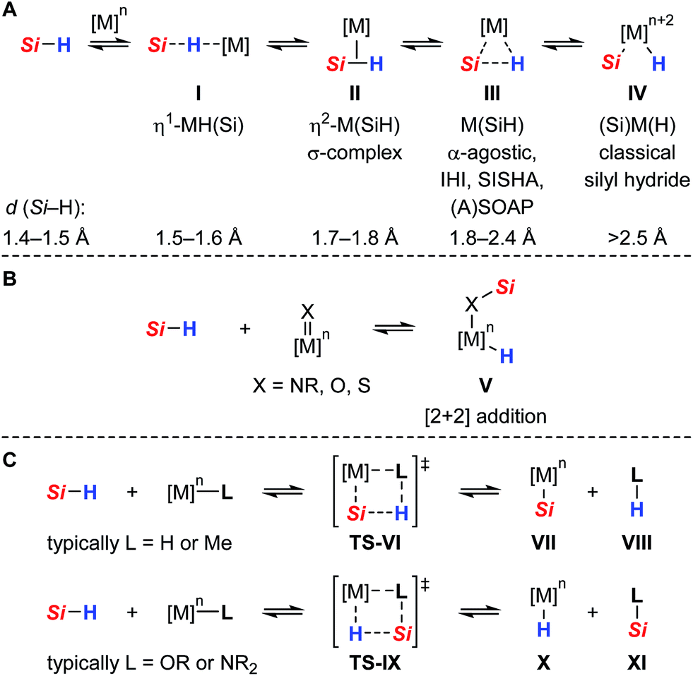 | ||
| Scheme 1 Diverse bonding scenarios in the Si–H bond activation by transition metal complexes [IHI = interligand hypervalent interactions, SISHA = secondary interactions between a silicon and a hydrogen atom, (A)SOAP = (a)symmetric oxidation addition products, and Si = R3Si = triorganosilyl]. | ||
Compared to the classical oxidative addition pathway commonly proposed, heterolytic Si–H bond activation with transition metals is less well-established and was initially postulated by Luo and Crabtree in the iridium(III)-catalyzed alcoholysis of hydrosilanes.7 Since this report, several transition metal mediated heterolyses of Si–H bonds have been documented.8 In most cases, however, a highly reactive silicon electrophile was generated through coordination to a cationic metal center and subsequently trapped in a less controlled manner by intermolecular reaction with adventitious water, the solvent (e.g. CH2Cl2), or counteranion (e.g. OTf−, SbF6− or BF4−). A few examples of intramolecular cooperative Si–H bond activation were shown where the Si–H bond is preferentially split across a polar M![[double bond, length as m-dash]](https://www.rsc.org/images/entities/char_e001.gif) X double bond (cf.Scheme 1B with X = NR, O, S), using early or middle transition metals in high oxidation states where oxidative addition is not possible or unlikely [e.g. Ti(IV), Ta(V), Re(V)].8f–o Although this activation mode allowed for the isolation and crystallographic characterization of unique hydrosilane adducts, as specified by complex V, its synthetic use and application to catalytic processes is still out of the ordinary and mainly restricted to hydrosilylation reactions.8
X double bond (cf.Scheme 1B with X = NR, O, S), using early or middle transition metals in high oxidation states where oxidative addition is not possible or unlikely [e.g. Ti(IV), Ta(V), Re(V)].8f–o Although this activation mode allowed for the isolation and crystallographic characterization of unique hydrosilane adducts, as specified by complex V, its synthetic use and application to catalytic processes is still out of the ordinary and mainly restricted to hydrosilylation reactions.8
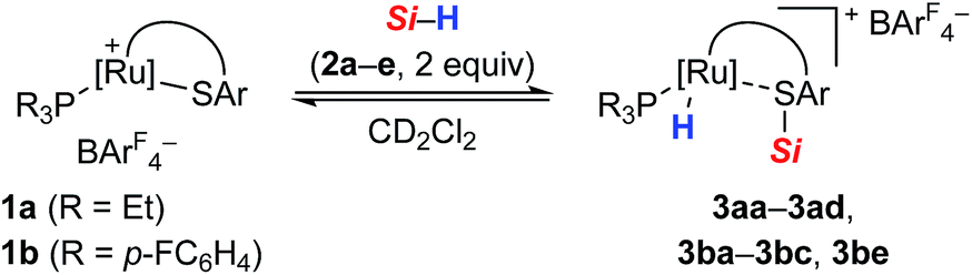
As part of our ongoing research endeavors of exploring new approaches to the generation of silicon electrophiles, we introduced the cationic ruthenium(II) thiolate complexes 1 (with ArF = 3,5-bis(trifluoromethyl)phenyl, Scheme 2, top right).9 The tethered bulky 2,6-dimesitylphenyl thiolate (SDmp) ligand stabilizes the coordinatively unsaturated metal center in 1 and also prevents formation of binuclear sulfur-bridged complexes. The polar Ru–S bond of these (formally) 16-electron complexes combines Lewis acidity at the metal center and Lewis basicity at the adjacent sulfur atom. We reasoned that this motif that could be considered as a transition metal frustrated Lewis pair (FLP)10 mediates the heterolytic cleavage of Si–H bonds, generating a metal hydride and a sulfur-stabilized silicon cation (Scheme 2, top left).11 This assumption was corroborated by a related study of Stradiotto and co-workers, reporting the addition of the Si–H bond of Ph2SiH2 and PhSiH3 across the M–S bond of cationic [Cp*M(κ2-3-PiPr2-2-S-indene)]+[B(C6F5)4]− complexes (with M = RhIII and IrIII).12 Compared to harder nitrogen or oxygen donors, the interaction with the soft sulfur atom was expected to give a more reactive silicon electrophile.11b,13 In addition, weak stabilization ought to favor reversible coordination, thereby facilitating R3Si+-transfer and securing turnover in catalytic processes. The rationally designed complexes 1 indeed proved to serve as potent catalysts for the facile activation not only of Si–H14 but also H–H9 and B–H15 bonds. Since our initial report on Si–H bond activation,14a we have disclosed a number of catalytic transformations, including dehydrogenative silylations,14a–d chemoselective hydrosilylations,14e,f as well as hydrodefluorination reactions14g (Scheme 2, bottom). It is interesting that Stradiotto and co-workers had been able to apply their rhodium(III) thiolate complex in ketone hydrosilylation (not shown)12 where we later observed dehydrogenative silyl enol ether formation with our system.14b All catalyses proceeded already at room temperature, neither requiring a hydrogen acceptor nor an added base for the catalytic cycle to close.
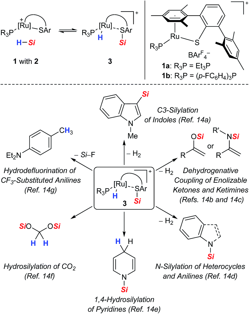 | ||
| Scheme 2 Proposed cooperative Si–H bond heterolysis by ruthenium(II) thiolate complexes 1 (top) and reported catalytic applications (bottom). | ||
Encouraged by the broad spectrum of catalytic reactions that were accomplished by using a single catalyst, we pursued an in-depth analysis of the Si–H bond activation event by ruthenium(II) thiolate complexes 1. Since the activation mode naturally impacts the course and outcome of a reaction, its mechanistic understanding is of vital importance and provides useful insights for the future design and development of more efficient catalysts.
All proposed mechanistic assumptions have so far relied on the heterolytic splitting of the Si–H bond at the polar Ru–S bond in 1 (cf.Scheme 2, top left) and have been primarily based on the interpretation of experimental observations.12,14 In view of the fact that the ruthenium(II) metal center is coordinatively unsaturated and in low oxidation state several possibilities of Si–H bond activation exist (Chart 1). Aside from the proposed cooperative activation mode (cf.3 in Chart 1), addition of the Si–H bond across the Ru–S bond with reversed regioselectivity might occur, leading to metal silyl complex 4 (cf.Scheme 1C). Since tetracoordinate silicon readily expands its coordination sphere, activation of the hydrosilane through coordination to the Lewis basic sulfur atom as in 5 needs to be considered. Moreover, pathways without participation of the sulfur atom are another option. These could proceed via electrophilic activation of the Si–H bond either by η1 (end-on) or η2 (side-on) coordination (cf.6 and 6′, respectively), followed by heterolytic cleavage of the Si–H bond by an externally added nucleophile. Likewise, full homolytic cleavage of the hydrosilane via classical oxidative addition affording metal silyl hydride 7 cannot be ignored. Therefore, several mechanistic questions have remained, including the role of the thiolate ligand.12
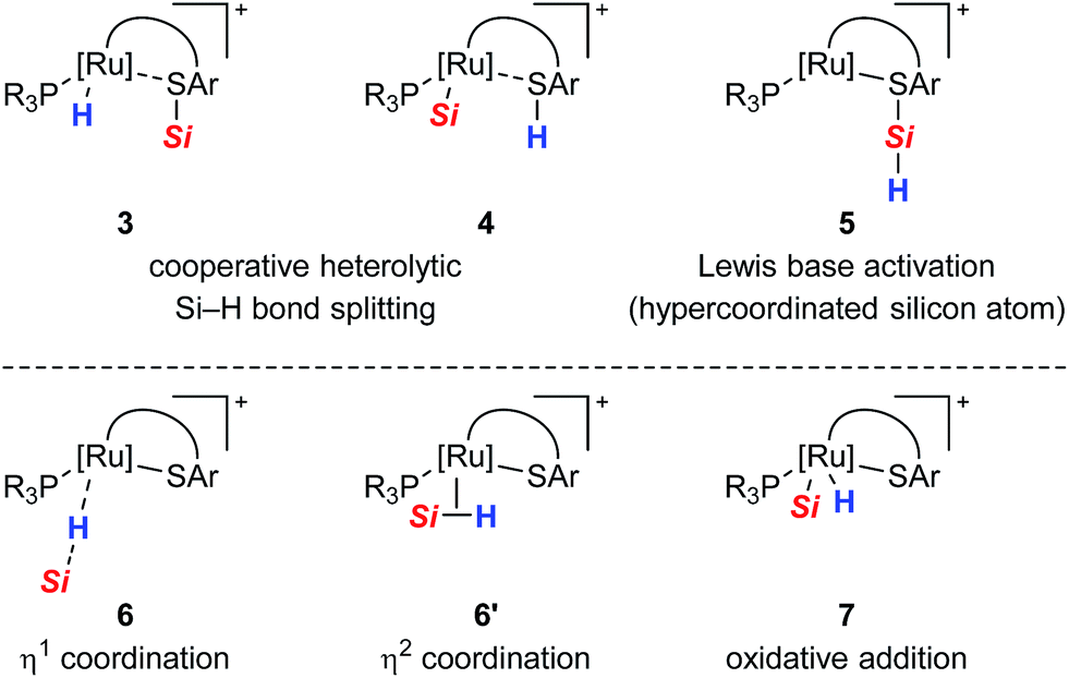 | ||
| Chart 1 Possible modes for the Si–H bond activation by ruthenium(II) thiolate complexes 1 with (top) and without (bottom) participation of the sulfur atom. | ||
We report here the results of our mechanistic study on hydrosilane activation promoted by ruthenium(II) thiolate complexes 1. By using various NMR techniques, we were able to detect the key intermediate of the Si–H bond activation step and fully assign its structure. The mechanism was further elucidated with the aid of a deuterium-labeled and a silicon-stereogenic hydrosilane as a stereochemical probe. Supported by quantum-chemical calculations, the experimental findings provide compelling evidence for a cooperative Si–H bond activation pathway that is in accordance with our originally formulated mechanistic model (cf.Scheme 2, top left)14 and Stradiotto's work.12 Finally, we succeeded in the isolation and crystallographic characterization of the sensitive silylthioruthenium hydride intermediate 3.
Results and discussion
From our previous studies, we already knew that Si–H bond activation with cationic ruthenium(II) thiolate complexes 1 is remarkable facile, proceeding instantly at room temperature.14 The tethered coordination mode of the SDmp ligand proved to be crucial: while the lability of a monodentate thiolate ligand in related rhodium(III) and iridium(III) complexes16 resulted in decomposition and formation of various metal hydride species in the presence of hydrosilanes, the two-point binding mode in 1 imparts increased stability to the Ru–S bond. In addition, this motif leads to structural rigidity and improved steric accessibility of the Ru–S bond, as seen in the molecular structure of these complexes.9Elucidation of the Si–H bond activation by NMR spectroscopy
To gain deeper insight into the Si–H bond activation, we performed a detailed NMR study using one- and two-dimensional multinuclear NMR measurements. In an initial investigation, monitoring the reaction of ruthenium(II) thiolate complex 1a (R3P = Et3P) with hydrosilanes under typical catalysis conditions (room temperature, excess hydrosilane) emerged as difficult since dynamic processes led to significant line-broadening in the NMR spectra.14a However, we identified the combination of complex 1b where the ruthenium atom is coordinated by a para-fluorinated aryl phosphine and MePh2SiH (2a) to be particularly suitable for NMR studies. Treatment of 1b with two equivalents of MePh2SiH (2a) at ambient temperature resulted in an immediate color change from green to yellow, “visualizing” successful Si–H bond activation. Clearly resolved spectra, obtained in both C6D6 and CD2Cl2 (with slightly better resolution in CD2Cl2, see the ESI† for details) were consistent with formation of hydrosilane adduct 3ba (1b → 3ba, Scheme 3).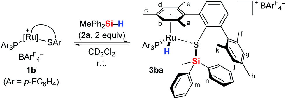 | ||
| Scheme 3 Cooperative Si–H bond heterolysis with ruthenium(II) thiolate complex 1b. | ||
The reaction proceeded cleanly, and resonance signals of unsaturated ruthenium(II) thiolate complex 1b were no longer detectable. Instead, a doublet at −7.5 ppm in the 1H NMR spectrum (Fig. 1) provided unambiguous evidence for a phosphine-ligated ruthenium hydride (ruling out intermediates 4 and 5). The absence of any 1JH,Si satellites, typically observed for η1 and η2 hydrosilane complexes, further supported complete Si–H bond cleavage (making 6 and 6′ unlikely). The coupling constant of 47 Hz is in the typical range for 2JH,P couplings and was also identified in the 31P NMR spectrum at 48.5 ppm whereas a singlet is observed at 30.0 ppm for complex 1b. While the latter is Cs symmetric, the additional hydride ligand creates a chiral center at the ruthenium atom in 3ba. This is also reflected in the 1H NMR spectrum that shows six rather than four singlets for the methyl groups and four rather than two signals for the meta-CH groups of the SDmp ligand (Fig. 1).
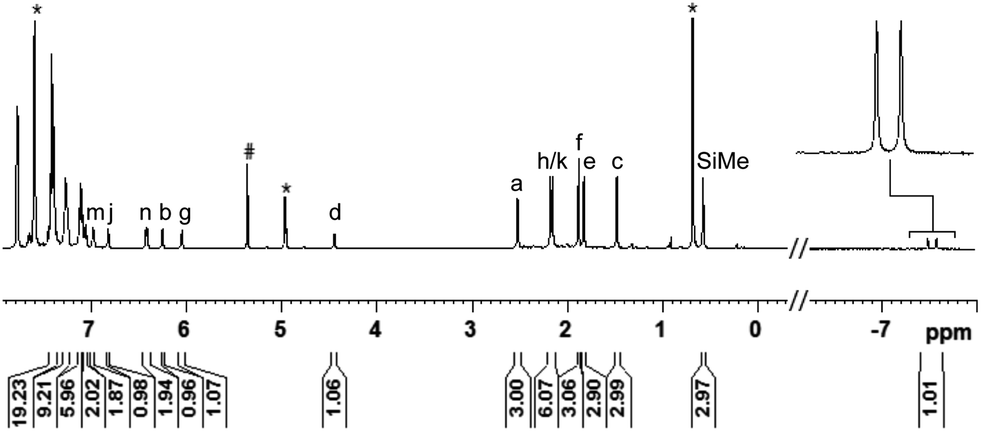 | ||
| Fig. 1 1H NMR spectrum (500 MHz, CD2Cl2, 300 K) of adduct 3ba, formed by reaction of complex 1b and hydrosilane 2a [# = CDHCl2, * = excess MePh2SiH (2a)]. | ||
Using a 1H, 29Si HMQC experiment, a 29Si NMR resonance signal was detected at 20.1 ppm, significant downfield shifted (Δδ = 37.6 ppm) relative to free MePh2SiH (2a, δ = −17.5 ppm). This is an indication for the generation of an electrophilic silicon species and is in accordance with postulated intermediate 3ba.17 For comparison, the corresponding neutral silyl thioether MePh2SiSDmp (for its preparation and characterization, see the ESI†) that features an S–Si linkage without an adjacent metal center is characterized by a 29Si NMR chemical shift of 2.9 ppm [Δδ = 20.4 ppm relative to MePh2SiH (2a)]. The substantial deshielding of the silicon nucleus in hydrosilane adduct 3ba reveals a strong influence of the metal center on its Lewis acidity that is expected to be higher compared to MePh2SiSDmp. The latter is in fact not a potent silyl transfer agent.
All NMR signal assignments were also confirmed by our state-of-the-art relativistic calculations of NMR chemical shifts at the four-component matrix Dirac–Kohn–Sham (mDKS) level18 (cf.Table 1 and S2 in the ESI† for detailed data). Spin–orbit (SO) effects were found to have a sizeable shielding contribution to both 1H (up to −3.1 ppm) and 31P (up to −35 ppm) NMR chemical shifts, owing to the large involvement of both ruthenium 4d-orbitals and ligand s-orbitals in metal–ligand binding.18,19
|
|
||||||||||
|---|---|---|---|---|---|---|---|---|---|---|
| Entry | Reaction | 1H NMR | 29Si NMRc | 31P NMR | ||||||
| δ(Si–H) [ppm] | δ(Ru–H)d [ppm] | Δδ(1H)e [ppm] | δ(Si–H) [ppm] | δ(S–Si) [ppm] | Δδ(29Si)f [ppm] | δ(1) [ppm] | δ(3) [ppm] | Δδ(31P)g [ppm] | ||
| a All reactions were performed in an NMR tube using ruthenium(II) thiolate complex 1a or 1b (1.0 equiv., 20 mM) and the corresponding hydrosilane 2 (2.0 equiv.). b In parentheses, NMR chemical shifts calculated at the four-component mDKS level using the PBE functional and the GIAO method in conjunction with Dyall's VDZ basis set on Ru and fully uncontracted IGLO-II basis sets on the ligand atoms (cf. computational details and Table S2 in the ESI†). c 1H, 29Si HMQC NMR spectroscopy optimized for J = 8 Hz. d The resonance appears as a doublet with a coupling constant of 47–50 Hz. e Δδ(1H) = δ(Ru–H) − δ(Si–H). f Δδ(29Si) = δ(S–Si) − δ(Si–H). g Δδ(31P) = δ(3) − δ(1). h In CD2Cl2 at 250 K. i In CD2Cl2 at 300 K. | ||||||||||
| 1h | 1a + MePh2SiH (2a) → 3aa | 4.8 | −8.2 (−7.8)b | −13.0 | −17.5 | 18.2 (14.8)b | 35.7 | 23.0 (23.0)b | 39.8 (37.2)b | 16.8 |
| 2h | 1a + Me2PhSiH (2b) → 3ab | 4.4 | −8.3 (−7.9)b | −12.7 | −17.0 | 28.4 (33.5)b | 45.4 | 23.0 | 40.4 (36.7)b | 17.4 |
| 3i | 1a + Et3SiH (2c) → 3ac | 3.7 | −8.0 | −11.7 | 0.4 | 41.0 | 40.6 | 23.0 | 40.1 | 17.1 |
| 4i | 1a + EtMe2SiH (2d) → 3ad | 3.7 | −8.1 (−7.8)b | −11.8 | −10.7 | 39.0 (44.1)b | 49.7 | 23.0 | 40.2 (38.2)b | 17.2 |
| 5i | 1b + MePh2SiH (2a) → 3ba | 4.8 | −7.5 (−7.6)b | −12.3 | −17.5 | 20.1 (28.3)b | 37.6 | 30.0 (31.6)b | 48.5 (39.7)b | 18.5 |
| 6i | 1b + Me2PhSiH (2b) → 3bb | 4.4 | −7.7 (−7.5)b | −12.1 | −17.0 | 29.8 (33.3)b | 46.8 | 30.0 | 48.7 (41.3)b | 18.7 |
| 7i | 1b + Et3SiH (2c) → 3bc | 3.7 | −7.6 | −11.3 | 0.4 | 41.6 | 41.2 | 30.0 | 48.8 | 18.8 |
| 8i | 1b + iPrMePhSiH (2e) → 3be | 4.3 | −7.7 | −12.0 | −6.4 | 32.1 | 38.5 | 30.0 | 47.2 | 17.2 |
The analysis of the NMR spectroscopic data, including further 2D NMR measurements (see the ESI† for details), clearly supports the structural assignment of adduct 3ba. Evidence for the intact Ru–S bond is provided by a 3JC,H coupling in the 1H, 13C HMBC NMR spectrum between the quaternary sulfur-substituted carbon atom of the SDmp ligand and the ruthenium hydride. However, unambiguous information about the existence of an S–Si linkage and the reversibility of the Si–H bond activation step was still elusive. A 1H, 1H EXSY NMR then shed light on this problem: cross peaks revealed chemical exchange between the hydrides of Ru–H and MePh2Si–H on the NMR time scale (Fig. 2, upper); further exchange effects were found in the alkyl and aryl range (Fig. 2, lower). The two phenyl groups at the silicon atom are chemically inequivalent, showing chemical exchange between each other and the phenyl group of the free hydrosilane ([m,n,Ph2Si]). Surprisingly, chemical exchange is also observed for the “half-sites” of the SDmp ligand. These findings can be rationalized by cooperative Si–H bond activation. Heterolytic splitting of the Si–H bond across the polar Ru–S bond not only generates a stereogenic metal center but also stereogenicity at the sulfur atom. By reversible syn-addition from either side (front or back), the resulting enantiomers of 3ba are in equilibrium, and this is exactly what is observed as chemical exchange between the diastereotopic protons of [a,e], [b,d], [f,k], and [g,j] (Scheme 4). The syn-selectivity of the activation step was secured by the absence of any detectable diastereomers of 3ba.
 | ||
| Fig. 2 Selected segments of the 1H, 1H EXSY NMR spectrum (500/500 MHz, CD2Cl2, 300 K, Tm = 200 ms) of adduct 3ba, formed by reaction of complex 1b and hydrosilane 2a. | ||
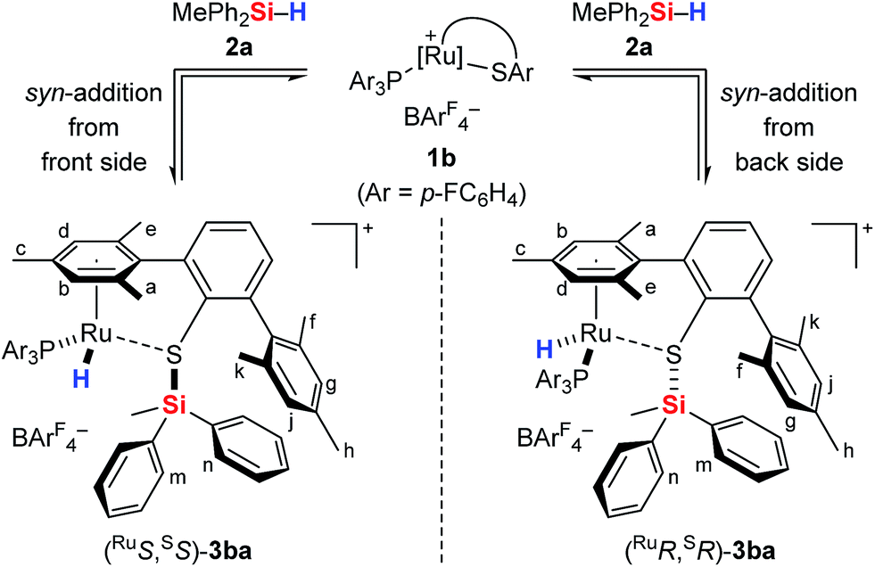 | ||
| Scheme 4 Reversible syn-addition of the Si–H bond across the Ru–S bond. | ||
The role of the phosphine ligand and the substitution pattern at the silicon atom
Having elucidated a cooperative hydrosilane activation mode, we next examined the reaction of hydrosilanes 2a–e with complexes 1a and 1b. In all cases, successful Si–H bond heterolysis was monitored by NMR spectroscopy. The characteristic 1H, 29Si, and 31P NMR chemical shifts of the various hydrosilane adducts 3 as well as the corresponding free hydrosilanes 2 and thiolate complexes 1 are collected in Table 1. While the resonance signals for mixtures of ruthenium complex 1a, decorated with a Et3P ligand, and hydrosilanes 2a and 2b were too broad to be observed at 300 K, better resolved NMR resonances are obtained at 250 K (entries 1 and 2). The 1H NMR spectra of adducts 3 each feature two signature resonances, one corresponding to the Si–H group of excess hydrosilane 2 (3.7–4.8 ppm) and one upfield-shifted doublet for the ruthenium hydride either at around −8.2 (for 3aa–3ad, entries 1–4) or −7.6 ppm (for 3ba–3bc and 3be, entries 5–8). The 29Si NMR resonances of adducts 3 (18.2–41.6 ppm) are shifted to higher frequencies relative to 2 (−17.5 to 0.6 ppm), indicating decreased electron density at the silicon atom.17 Although this is an oversimplified argument (for instance, a rather poor correlation, if any, between 29Si NMR chemical shifts and atomic charges on the silicon atom in ferrocene-stabilized silylium ions was found in our previous study20), the more electrophilic nature of the silicon atom in hydrosilane adducts 3 as compared to the starting hydrosilanes 2 is also evident from NPA charge analysis (cf. Table S4 in the ESI†). As expected, the 29Si NMR chemical shifts are sensitive towards the substituents at the silicon atom, and the highest downfield shifts of 3 are observed for trialkylsilanes 2c and 2d (entries 3, 4, and 7). The 31P NMR chemical shifts are static again, and a resonance at 40 ppm is characteristic for 3aa–3ad (entries 1–4), whereas a chemical shift at 48 ppm is indicative for 3ba–3bc and 3be (entries 5–8). The overall trends in the NMR spectroscopic data reveal that the phosphine ligand mainly influences the electronic nature of the ruthenium hydride while the Lewis acidity of the silicon electrophile is largely controlled by the substitution pattern at the silicon atom.Mechanistic control experiments with deuterium-labeled and silicon-stereogenic hydrosilanes
To further probe the Si–H bond activation step, control experiments employing deuterium-labeled MePh2SiD (2a-d1) were performed. As expected, reaction of ruthenium(II) thiolate complex 1b with two equivalents of deuterosilane 2a-d1 in CD2Cl2 at room temperature resulted in complete incorporation of deuterium into adduct 3ba-d1 (not shown). In 1H/2H scrambling experiments, deuterium-labeled Me2PhSiD (2b-d1) was treated with non-deuterated MePh2SiH (2a) in the presence of catalytic amounts of either complex 1a or 1b at room temperature (Scheme 5). Whereas 1H/2H exchange was fast and complete with ruthenium(II) thiolate complex 1a, no scrambling was observed with 1b even after 3 h. | ||
| Scheme 5 1H/2H scrambling experiments: the crucial role of the phosphine ligand. | ||
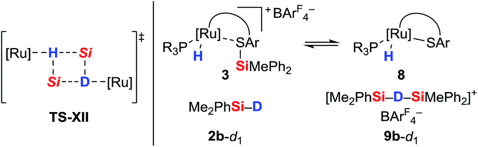
The pronounced differences in reactivity of both complexes led us to investigate the role of the phosphine ligand (Et3P in 1aversus (p-FC6H4)3P in 1b) in more detail. Since electron-rich Et3P is a stronger σ-donor than the electron-deficient para-fluorinated aryl phosphine, the ruthenium hydride in hydrosilane adduct 3a is expected to be a better hydride donor than in 3b. On the other hand, 3b is likely to be a better R3Si+-transfer reagent compared to 3a. Both of these properties will contribute to the 1H/2H exchange, depending on whether this process proceeds through a σ-bond metathesis6 solely involving the metal hydride (TS-XII, Scheme 6, left)21 or through formation of hydronium ions 9 ([Si–H–Si]+)22 by R3Si+-transfer to a free hydrosilane (Scheme 6, right).
 | ||
| Scheme 6 Possible pathways for 1H/2H exchange. | ||
The use of a silicon-stereogenic hydrosilane as a stereochemical probe finally allowed to distinguish between these two mechanisms: enantioenriched hydrosilane (SiS)-2e was reisolated with complete retention of configuration at the silicon atom after treatment with complex 1b (Scheme 7). On the basis of this result, the generation of hydronium ions is highly unlikely, as this pathway would result in racemization. The better hydride donor strength of 3a thus is likely to account for the 1H/2H exchange.
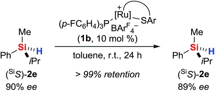 | ||
| Scheme 7 Control experiment with a silicon-stereogenic hydrosilane: no support for the intermediacy of hydronium ions. | ||
Isolation and crystallographic characterization of hydrosilane adducts 3ab and 3ad
To provide unambiguous evidence for the generation of silylthioruthenium hydride intermediates, we pursued the crystallization of hydrosilane adducts 3. Single crystals suitable for X-ray diffraction were obtained for 3ab as well as 3ad at −30 °C from a solution of complex 1a in neat hydrosilane, either Me2PhSiH (2b) or EtMe2SiH (2d). Compared to the Ru–S bond in coordinatively unsaturated complex 1a (2.21 Å), the molecular structure of 3ab shows a slightly elongated (about 8%) yet intact Ru–S bond (2.39 Å, Fig. 3).9 The Si–H bond is completely broken and an interatomic Si⋯H distance of 3.17 Å indicates no interaction of the silicon with the hydrogen atom. While the hydride is bound to the ruthenium center with a bond length of 1.58 Å, the silicon atom is connected to the sulfur atom with a distance of 2.24 Å. This S–Si distance is slightly elongated (about 6–7%) compared to structurally related neutral ruthenium(II) silylthiolate complexes (2.11 Å (ref. 23a) and 2.09 Å (ref. 23b)). The average C–Si–C angle of 110.5° reflects a tetrahedral (silylated sulfonium ion) rather than a trigonal planar (sulfur-stabilized silicon cation) coordination around the silicon atom. All selected bond lengths and angles of the EtMe2SiH adduct 3ad are comparable to those of 3ab and are in excellent agreement with the DFT optimized structures (see the ESI† for detailed data).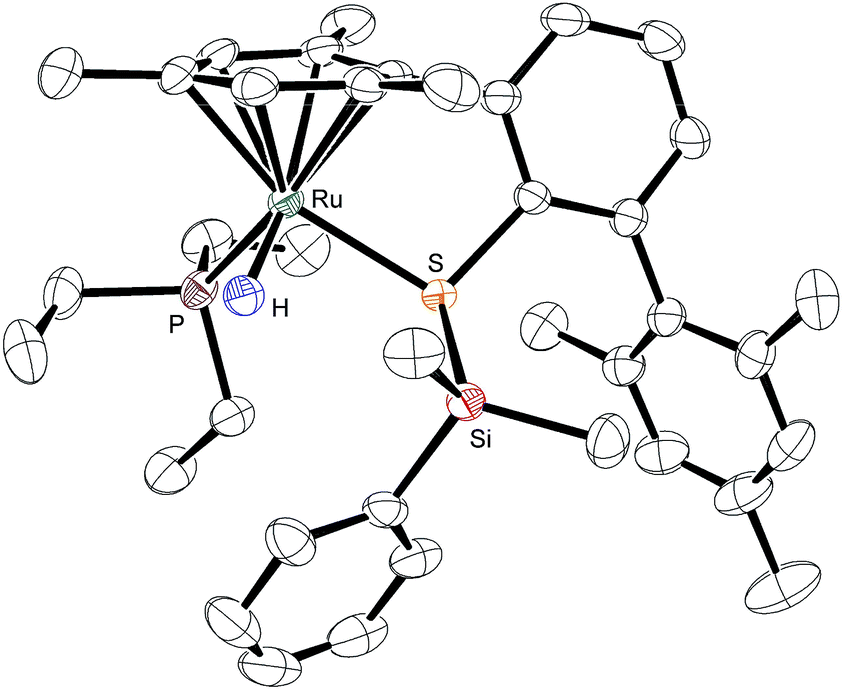 | ||
| Fig. 3 ORTEP diagram of the molecular structure of 3ab. Thermal ellipsoids are shown at the 50% possibility level. Hydrogen atoms, except for the ruthenium hydride, and the counteranion are omitted for clarity. Selected interatomic distances (Å): Si⋯H, 3.17(4); S–Si, 2.2445(11); Ru–H, 1.58(4); Ru–S, 2.3882(10). For comparison, the DFT-optimized distances (Å) are as follows: Si⋯H, 3.188; S–Si, 2.255; Ru–H, 1.60; Ru–S, 2.394. | ||
Isolation and characterization of [R3POSiR′3]+[BArF4]− (10)
During our NMR spectroscopy studies, we noticed the presence of minor amounts of another species next to hydrosilane adduct 3 in the majority of the measurements. This observation became apparent by a second high-frequency-shifted signal in both the 29Si NMR and 31P NMR spectra. For instance, when ruthenium(II) thiolate complex 1a was treated with MePh2SiH (2a) to generate 3aa, an additional minor peak was observed at 8.8 ppm in the 29Si NMR spectrum and at 92.9 ppm in the 31P NMR spectrum (later assigned to 10aa; for a tabulated summary of all combinations of 1 and 2 to form 10, see Table S1 in the ESI†). While the structure determination solely on the basis of NMR spectroscopy failed, the calculated mass for [(p-FC6H4)3POSiMePh2]+ (10ba+) was found by ESI mass spectrometry. We were then able to crystallize the related silyloxyphosphonium salt [Et3POSiMe2Ph]+[BArF4]− (10ab), providing conclusive evidence for our structural assignment (Fig. 4). Single crystals of 10ab suitable for X-ray diffraction were obtained from a solution of ruthenium(II) thiolate complex 1a and excess hydrosilane 1b in toluene layered by n-hexane at −30 °C.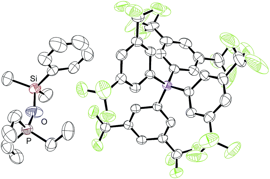 | ||
| Fig. 4 ORTEP diagram of the molecular structure of [Et3POSiMe2Ph]+[BArF4]− (10ab). Thermal ellipsoids are shown at the 50% possibility level. Hydrogen atoms are omitted for clarity. Selected bond lengths (Å): Si–O, 1.674(4); P–O, 1.529(4). | ||
To further probe the structure and reactivity of the silyloxyphosphonium salts, we independently prepared [Et3POSiMePh2]+[BArF4]− (10aa) by treatment of in situ generated silylthioruthenium hydride intermediate 3ba with stoichiometric amounts of Et3PO (11a) in C6D6 (Scheme 8). Beside the expected chemical shift for ruthenium hydride complex 8b at 53.5 ppm, a resonance signal at 91.3 ppm was seen in the 31P NMR spectrum, matching with the observed side product found in the above-described preparation of hydrosilane adduct 3aa (cf. Table S1in the ESI,† entry 1).
 | ||
| Scheme 8 Independent preparation of [Et3POSiMePh2]+[BArF4]− (10aa). | ||
To test the ability of the silyloxyphosphonium salts to act as silyl transfer reagents, acetophenone was added to the independently prepared mixture of 10aa and 8b. No reaction was observed even at prolonged reaction times, thereby ruling out 10aa as an active species in our catalyses.14b The source of oxygen, however, remains unclear but traces of dioxygen cannot be fully excluded given the high reactivity of intermediate 3. Water is unlikely since this would result in immediate silanol or disiloxane formation, and neither various equivalents of the hydrosilane nor a change of the solvent had an effect on the proportion of 10.
DFT calculations
To gain deeper insight into the nature of the Si–H bond activation step and to identify possible intermediates, quantum-chemical calculations at the B3LYP-D3(BJ)/ECP/6-31+G(d,p) level including an atom-pairwise correction of Grimme's D3 model with Becke–Johnson (BJ) damping for dispersion forces and using an SMD solvation model to account for bulk solvent effects (benzene as a solvent) were performed (cf. computational details in the ESI†). Combination of various triaryl- and trialkylphosphine ligands and hydrosilanes [MePh2SiH (2a), Me2PhSiH (2b), EtMe2SiH (2d), tBuMe2SiH] were examined computationally. The free-energy profile together with the optimized structures of relevant intermediates and transition states for the reaction of ruthenium(II) thiolate complex 1a+ with Me2PhSiH (2b) is shown in Fig. 5 (selected structural parameters and thermodynamic data for the entire series of complexes studied in this work are collected in Table S3 in the ESI†).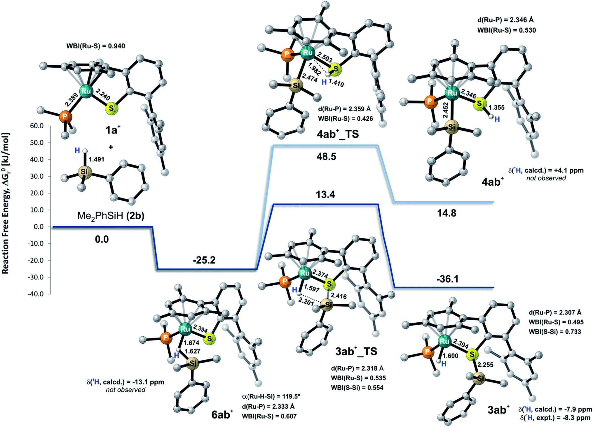 | ||
| Fig. 5 Calculated relative free energies ΔG0r together with the structure of relevant intermediates and transition states for the Si–H bond activation of Me2PhSiH (2b) by ruthenium(II) thiolate complex 1a+ (results obtained at the B3LYP-D3(BJ)/ECP/6-31+G** level of theory using an SMD solvation model). All C–H hydrogen atoms are omitted for clarity. Bond lengths are in Å. Computed and experimental 1H NMR shifts of intermediates are reported in ppm (with respect to TMS). Wiberg bond indices (WBI) of selected bonds are also indicated. | ||
Cooperative heterolysis of the Si–H bond commences with coordination of the hydrosilane to the unsaturated 16-electron [(R3P)Ru(SDmp)]+ complex 1+, filling the ruthenium(II) vacant coordination site by forming a stable η1- or η2-hydrosilane complex (cf.6 or 6′ in Chart 1). The coordination of the hydrosilane to ruthenium(II) thiolate complex 1+ was revealed as barrierless on the electronic energy surface, albeit the counteranion might affect the reaction barrier when ion-pair dissociation/formation takes place. The reaction is in most cases exergonic, with exception of the hydrosilane decorated with a bulky tert-butyl group, where the ΔG0r is slightly positive (cf. Table S3 in the ESI†). The bonding situation in the hydrosilane adducts 6+ depends on the nature of the phosphine ligand as well as on the hydrosilane (cf.Fig. 6). For instance, the sterically least demanding complex bearing a Me3P ligand prefers side-on η2 coordination of Me2PhSiH (2b) with a somewhat more elongated Si–H bond (1.794 Å) and a more acute α(Ru⋯H⋯Si) angle (99°) as compared to the η1-hydrosilane complex of 1a+ (with Et3P instead of Me3P) and Me2PhSiH (2b), featuring a Si–H bond distance of 1.627 Å and α(Ru⋯H⋯Si) angle of 120°. While the end-on η1-hydrosilane coordination appears to be driven mainly by steric hindrance (changing the electron-donating/-withdrawing substituents in the Ar3P ligand does not have any significant influence on the structural preference), the preference for a η2-H(Si) binding mode may be recovered by introducing a second phenyl group at the silicon atom (cf. Si–H bond distances in Table S3†). In spite of some structural and NMR spectroscopic differences between the η1- and η2-hydrosilane complexes (cf. Tables S2 and S3 in the ESI† for computed properties), the ΔG0r of their formation are very similar (cf. Table S3 in the ESI†), indicating a rather weak stabilization energy due to Ru–Si interaction in the side-on adduct. These observations are fully consistent with some of the previous findings of Brookhart and co-workers on iridium(III) hydrosilane complexes.24
 | ||
| Fig. 6 Cut-plane plots from ELI-D analyses of bonding in hydrosilane complexes 6 of [(R3P)Ru(SDmp)]+ (R3P = Me3P, upper left and R3P = Et3P, upper right) with Me2PhSiH (2b), and in silylthioruthenium hydride intermediate 3ab+ (lower). The gray-white regions represent ELI-D maxima (bonding attractors). | ||
In analogy to our previous study on iridium pincer complexes,25 we attempted to detect any intermediate experimentally by using NMR spectroscopy at low temperatures (note that the hydrosilane complexes 6+ and 6′+ are predicted to display a characteristic 1H hydride resonance shifted to lower frequencies by ca. −3 to −5 ppm as compared to those of the observed adducts 3; cf.Fig. 5 and Table S2 in the ESI†). Those attempts were, however, not successful, most likely due to the high reactivity of these species (vide infra). Irrespective of the hydrosilane binding mode (η1 or η2), the Ru–S bond length in these complexes is much longer (2.39–2.40 Å) than in the starting complex 1+ (∼2.24 Å; cf. Table S3 in the ESI†). Nevertheless, various bonding analyses including Wiberg bond indices (WBI, cf. Table S4 in the ESI†) and the electron localizability indicator (ELI-D; cf.Fig. 6, lower left) show the remaining partial Ru–S bonding character.
While a classical oxidative addition pathway (cf.7 in Chart 1) could not be located by the calculations, two different pathways for the heterolytic Si–H bond cleavage based on hydrosilane complexes 6+ or 6′+ have been investigated. These include either migration of the silyl group or the hydrogen atom to the sulfur atom of the SDmp ligand. The hydrogen transfer has been found to be energetically disfavored by more than 30 kJ mol−1 in both the transition state energy and in the free energy of the products when compared to the transfer of a silylium ion. This coincides with the experimental observations that a ruthenium silyl complex (cf.4 in Chart 1) could not be detected by NMR spectroscopy (for predicted NMR shifts of these species, see Fig. 5 and Table S2 in the ESI†). The silyl transfer proceeds via a concerted four-membered transition state 3_TS with a remarkably weakened (broken) Si⋯H bond (∼2.15–2.25 Å) and a nearly completed S–Si bond (∼2.41–2.46 Å, Wiberg bond index ∼0.55; cf. Tables S3 and S4 in the ESI†). The transition states are computed to lie at ca. 10–75 kJ mol−1 relative to the reactants. In general, ruthenium(II) thiolate complexes that are decorated with a trialkylphosphine instead of a triarylphosphine ligand are found to have a lower reaction barrier by about 14–20 kJ mol−1. The highest barrier (56–75 kJ mol−1) is computed for reactions with tBuMe2SiH, which is by >20 kJ mol−1 higher compared to reactions using hydrosilanes such as Me2PhSiH (2b) and EtMe2SiH (2d). The overall Si–H bond activation process resulting in hydrosilane adducts 3+ is exergonic with ΔG0r ranging from ca. −20 to −40 kJ mol−1. Nevertheless, the higher reaction barrier in the case of tBuMe2SiH would explain why hydrosilanes decorated with bulky groups do not react with ruthenium(II) thiolate complexes 1 although the overall free reaction energy is negative. Notably, the catalytically active cation in 1 may also form ion pairs with the sterically demanding BArF4− counterion (particularly in organic solvents with low polarity), and that could additionally hamper the interaction of 1 with bulky substrates.
During the formation of complexes 6+ or 6′+, the Ru–S bond remains virtually intact and also preserves some bonding character in the hydrosilane adducts 3+. Attempts to locate a possible intermediate corresponding to the activation of the hydrosilane through coordination to the Lewis basic sulfur atom failed (cf.5 in Chart 1). This may be ascribed to a partial positive charge located on the sulfur atom in complex 1+, reducing its electron-donating ability. Upon binding of the hydrosilane, the positive charge at the sulfur atom diminishes, which enhances its Lewis basic properties (cf.Fig. 7 for MEP and Table S4 in the ESI†).
 | ||
| Fig. 7 Molecular electrostatic potentials (MEP) of [(Et3P)Ru(SDmp)]+ (1a+) and [(Et3P)Ru(SDmp)·Me2PhSiH]+ (6ab+). Isovalue surfaces are displayed at an electron density of 0.04 a.u. (B3LYP/ECP/6-31+G** results). Red and blue regions correspond to the extreme negative and positive potentials, respectively. | ||
Conclusions
In the light of the reactivity of ruthenium(II) thiolate complexes of type [(R3P)Ru(SDmp)]+[BArF4]− (1) in the activation of E–H bonds, e.g. H–H,9 Si–H,14 and B–H15 bonds, detailed mechanistic insight into the hydrosilane activation mode have been disclosed. A combined experimental, spectroscopic, crystallographic, and theoretical investigation provided conclusive evidence for a heterolytic Si–H bond activation pathway involving metal–ligand cooperativity.5 The principal results are summarized as follows:(1) The quantum-chemical analyses reveal that the hydrosilane is initially activated by coordination of the Si–H bond to the Lewis acidic metal center26 rather than Lewis base activation through the Lewis basic thiolate ligand, as often proposed for metal–alkoxide and –oxo complexes (cf.6 or 6′vs.5 in Chart 1). In accordance with previous studies,24 the exact coordination mode, either η1 (end-on) or η2 (side-on), is driven by the steric demand of the phosphine ligand as well as the substituents at the silicon atom. While the η1-complexes can be considered as a more potent source of electrophilic silicon, the energy differences are very small, indicating a rather weak stabilization energy due to ruthenium to σ*(Si–H) backbonding. Both coordination modes are barrierless on the electronic energy surface and could not be detected spectroscopically.
(2) After electrophilic activation, the Si–H bond is heterolytically split at the polar Ru–S bond via a concerted four-membered transition state (cf.3ab+_TS in Fig. 5). The σ-bond metathesis results in formation of a cationic silylthioruthenium hydride intermediate (cf.3 in Chart 1), combining a ruthenium(II) hydride and a sulfur-stabilized silicon cation, i.e. metallasilylsulfonium ion, in one molecule.12
(3) Addition of the Si–H bond across the Ru–S bond with reversed regioselectivity, affording a ruthenium silyl complex with a ligated thiol (cf.4vs.3 in Chart 1), is energetically disfavored by more than 30 kJ mol−1.
(4) The Ru–S bond remains virtually intact during the Si–H bond activation event, even preserving bonding character in the hydrosilane adducts (Wiberg bond indices around 0.5).
(5) The overall Si–H bond activation process is reversible and exergonic with ΔG0r ranging from −20 to −40 kJ mol−1, proceeding instantly already at low temperatures.
(6) The spectroscopic and computational characterization of the stable yet reactive cationic silylthioruthenium hydride intermediates is reported. Unambiguous proof for the structural assignment was provided by the successful isolation and crystallographic characterization of these catalytically active key intermediates. The computational data are in full accordance with the experimental findings.
(7) The regioselective and stereospecific syn-addition of the Si–H bond was further verified with the aid of deuterium labeling and a silicon-stereogenic hydrosilane as a stereochemical probe.
(8) The analysis of the NMR spectra indicated the presence of a side product, which could be identified crystallographically as silyloxyphosphonium salt [R3POSiR′3]+[BArF4]−. Even though its formation remains unclear, these species have been shown to be catalytically inactive.
Overall, the mechanistic details of the Si–H bond activation at polar Ru–S bonds have been clarified. Compared to nature, where a polar Ni–S bond potentially serves as a reactive site for heterolytic dihydrogen splitting in [NiFe] hydrogenases,27 the present study of the closely related hydrosilane activation represents, next to Stradiotto's seminal report,12 a rare example of a fully-understood system of heterolytic bond splitting mediated by a transition metal thiolate complex and might provide a solid foundation for the understanding of the basic mechanistic principles of both processes.
Acknowledgements
This research was supported by the Fonds der Chemischen Industrie (predoctoral fellowship to T.S., 2011–2013), the Deutsche Forschungsgemeinschaft (International Research Training Group Münster-Nagoya, GRK 1143 with a predoctoral fellowship to C.D.F.K., 2011–2012), and the Cluster of Excellence Unifying Concepts in Catalysis of the Deutsche Forschungsgemeinschaft (EXC 314/2). M.O. is indebted to the Einstein Foundation (Berlin) for an endowed professorship. We thank Dr Kazuki Tanifuji (Nagoya University) for expert advice with the X-ray structure analyses and Marko Vastag (research group of Dr Inez Weidinger and Prof. Dr Peter Hildebrandt, TU Berlin) for attempted resonance Raman measurements.Notes and references
- S. Rendler and M. Oestreich, in Modern Reduction Methods, ed. P. G. Andersson and I. J. Munslow, Wiley-VCH, Weinheim, 2008, ch. 8, pp. 183–207 Search PubMed.
- For authoritative reviews of hydrosilane activation by transition metals, see: (a) J. Y. Corey, Chem. Rev., 2011, 111, 863–1071 CrossRef CAS PubMed; (b) J. Y. Corey and J. Braddock-Wilking, Chem. Rev., 1999, 99, 175–292 CrossRef CAS PubMed.
- The nonclassical interactions may be viewed as arrested intermediates (“snapshots”) along the reaction coordinate towards oxidative addition. For reviews, see: (a) G. Alcaraz and S. Sabo-Etienne, Coord. Chem. Rev., 2008, 252, 2395–2409 CrossRef CAS; (b) S. Lachaize and S. Sabo-Etienne, Eur. J. Inorg. Chem., 2006, 2115–2127 CrossRef CAS; (c) G. I. Nikonov, Adv. Organomet. Chem., 2005, 53, 217–309 CrossRef CAS; (d) Z. Lin, Chem. Soc. Rev., 2002, 31, 239–245 RSC; (e) G. I. Nikonov, J. Organomet. Chem., 2001, 635, 24–36 CrossRef CAS; (f) J. J. Schneider, Angew. Chem., Int. Ed. Engl., 1996, 35, 1068–1075 CrossRef CAS; (g) R. H. Crabtree, Angew. Chem., Int. Ed. Engl., 1993, 32, 789–805 CrossRef; (h) U. Schubert, Adv. Organomet. Chem., 1990, 30, 151–187 CrossRef CAS; for a theoretical study, see: (i) W. Scherer, P. Meixner, J. E. Barquera-Lozada, C. Hauf, A. Obenhuber, A. Brück, D. J. Wolstenholme, K. Ruhland, D. Leusser and D. Stalke, Angew. Chem., Int. Ed., 2013, 52, 6092–6096 CrossRef CAS PubMed.
- For an overview of heterolytic splitting of Si–H bonds by electrophilic metal centers, see: G. J. Kubas, Adv. Inorg. Chem., 2004, 56, 127–177 CrossRef CAS.
- The synergistic reactivity of the metal center and coordinated ligands is commonly termed as cooperative, metal–ligand cooperating (MLC), ambifunctional or bifunctional catalysis. For reviews, see: (a) H. Grützmacher, Angew. Chem., Int. Ed., 2008, 47, 1814–1818 CrossRef PubMed; (b) J. I. van der Vlugt and J. N. H. Reek, Angew. Chem., Int. Ed., 2009, 48, 8832–8846 CrossRef CAS PubMed; (c) M. Stradiotto, K. D. Hesp and R. J. Lundgren, Angew. Chem., Int. Ed., 2010, 49, 494–512 CrossRef CAS PubMed; (d) Topics in Organometallic Chemistry, Bifunctional Molecular Catalysis, ed. T. Ikariya and M. Shibasaki, Springer, Heidelberg, 2011, vol. 37 Search PubMed; (e) C. Gunanathan and D. Milstein, Acc. Chem. Res., 2011, 44, 588–602 CrossRef CAS PubMed; (f) S. Kuwata and T. Ikariya, Chem.–Eur. J., 2011, 17, 3542–3556 CrossRef CAS PubMed; (g) M. Kanai, in Organic Chemistry – Breakthroughs and Perspectives, ed. K. Ding and L.-X. Dai, Wiley-VCH, Weinheim, 2012, ch. 11, pp. 385–412 Search PubMed; (h) B. Askevold, H. W. Roesky and S. Schneider, ChemCatChem, 2012, 4, 307–320 CrossRef CAS; (i) J. I. van der Vlugt, Eur. J. Inorg. Chem., 2012, 363–375 CrossRef CAS; (j) G. R. Owen, Chem. Soc. Rev., 2012, 41, 3535–3546 RSC; (k) V. K. K. Praneeth, M. R. Ringenberg and T. R. Ward, Angew. Chem., Int. Ed., 2012, 51, 10228–10234 CrossRef CAS PubMed; (l) V. T. Annibale and D. Song, RSC Adv., 2013, 3, 11432–11449 RSC; (m) M. Trincado and H. Grützmacher, in Cooperative Catalysis, ed. R. Peters, Wiley-VCH, Weinheim, 2015, ch. 3, pp. 67–110 Search PubMed.
- (a) R. Waterman, Organometallics, 2013, 32, 7249–7263 CrossRef CAS; (b) R. N. Perutz and S. Sabo-Etienne, Angew. Chem., Int. Ed., 2007, 46, 2578–2592 CrossRef CAS PubMed; (c) Z. Lin, Coord. Chem. Rev., 2007, 251, 2280–2291 CrossRef CAS.
- X.-L. Luo and R. H. Crabtree, J. Am. Chem. Soc., 1989, 111, 2527–2535 CrossRef CAS.
- (a) S. Bourg, R. J. P. Corriu, M. Enders and J. J. E. Moreau, Organometallics, 1995, 14, 564–566 CrossRef CAS; (b) X. Verdaguer, U. E. W. Lange, M. T. Reding and S. L. Buchwald, J. Am. Chem. Soc., 1996, 118, 6784–6785 CrossRef CAS; (c) X. Liu, Z. Wu, Z. Peng, Y.-D. Wu and Z. Xue, J. Am. Chem. Soc., 1999, 121, 5350–5351 CrossRef CAS; (d) X. Liu, Z. Wu, H. Cai, Y. Yang, T. Chen, C. E. Vallet, R. A. Zuhr, D. B. Beach, Z.-H. Peng, Y.-D. Wu, T. E. Concolino, A. L. Rheingold and Z. Xue, J. Am. Chem. Soc., 2001, 123, 8011–8021 CrossRef CAS PubMed; (e) H. Cai, T. Chen, X. Wang, A. J. Schultz, T. F. Koetzle and Z. Xue, Chem. Commun., 2002, 230–231 RSC; (f) Z. K. Sweeney, J. L. Polse, R. A. Andersen, R. G. Bergman and M. G. Kubinec, J. Am. Chem. Soc., 1997, 119, 4543–4544 CrossRef CAS; (g) Z. K. Sweeney, J. L. Polse, R. G. Bergman and R. A. Andersen, Organometallics, 1999, 18, 5502–5510 CrossRef CAS PubMed; (h) T. E. Hanna, E. Lobkovsky and P. J. Chirik, Inorg. Chem., 2007, 46, 2359–2361 CrossRef CAS PubMed; (i) T. I. Gountchev and T. D. Tilley, J. Am. Chem. Soc., 1997, 119, 12831–12841 CrossRef CAS; (j) A. W. Kaplan, J. L. Polse, G. E. Ball, R. A. Andersen and R. G. Bergman, J. Am. Chem. Soc., 1998, 120, 11649–11662 CrossRef CAS; (k) P. J. Tiong, A. Nova, E. Clot and P. Mountford, Chem. Commun., 2011, 47, 3147–3149 RSC; (l) J. J. Kennedy-Smith, K. A. Nolin, H. P. Gunterman and F. D. Toste, J. Am. Chem. Soc., 2003, 125, 4056–4075 CrossRef CAS PubMed; (m) K. A. Nolin, J. R. Krumper, M. D. Pluth, R. G. Bergman and F. D. Toste, J. Am. Chem. Soc., 2007, 129, 14684–14696 CrossRef CAS PubMed; for a theoretical study on this work, see: (n) L. W. Chung, H. G. Lee, Z. Lin and Y.-D. Wu, J. Org. Chem., 2006, 71, 6000–6009 CrossRef CAS PubMed; for a review, see: (o) S. C. A. Sousa, I. Cabrita and A. C. Fernandes, Chem. Soc. Rev., 2012, 41, 5641–5653 RSC; (p) A. Llamazares, H. W. Schmalle and H. Berke, Organometallics, 2001, 20, 5277–5288 CrossRef CAS; (q) M. D. Fryzuk, J. B. Love, S. J. Rettig and V. G. Young, Science, 1997, 275, 1445–1447 CrossRef CAS; for a theoretical study on this work, see: (r) H. Basch, D. G. Musaev, K. Morokuma, M. D. Fryzuk, J. B. Love, W. W. Seidel, A. Albinati, T. F. Koetzle, W. T. Klooster, S. A. Mason and J. Eckert, J. Am. Chem. Soc., 1999, 121, 523–528 CrossRef CAS; (s) M. D. Fryzuk, B. A. MacKay and B. O. Patrick, J. Am. Chem. Soc., 2003, 125, 3234–3235 CrossRef CAS PubMed; (t) B. A. MacKay, R. F. Munha and M. D. Fryzuk, J. Am. Chem. Soc., 2006, 128, 9472–9483 CrossRef CAS PubMed; (u) J. Zhou, J. Chu, Y. Zhang, G. Yang, X. Leng and Y. Chen, Angew. Chem., Int. Ed., 2013, 52, 4243–4246 CrossRef CAS PubMed; (v) P. Deglmann, E. Ember, P. Hofmann, S. Pitter and O. Walter, Chem.–Eur. J., 2007, 13, 2864–2879 CrossRef CAS PubMed; (w) W.-Y. Chu, X. Zhou and T. B. Rauchfuss, Organometallics, 2015, 34, 1619–1626 CrossRef CAS.
- Y. Ohki, Y. Takikawa, H. Sadohara, C. Kesenheimer, B. Engendahl, E. Kapatina and K. Tatsumi, Chem.–Asian J., 2008, 3, 1625–1635 CrossRef CAS PubMed.
- (a) S. R. Flynn and D. F. Wass, ACS Catal., 2013, 3, 2574–2581 CrossRef CAS; (b) D. F. Wass and A. M. Chapman, Top. Curr. Chem., 2013, 334, 261–280 CrossRef PubMed.
- For silylsulfonium ions, see: (a) G. K. S. Prakash, S. Bae, Q. Wang, G. Rasul and G. A. Olah, J. Org. Chem., 2000, 65, 7646–7649 CrossRef CAS PubMed; (b) V. H. G. Rohde, P. Pommerening, H. F. T. Klare and M. Oestreich, Organometallics, 2014, 33, 3618–3628 CrossRef CAS.
- K. D. Hesp, R. McDonald, M. J. Ferguson and M. Stradiotto, J. Am. Chem. Soc., 2008, 130, 16394–16406 CrossRef CAS PubMed.
- U.-H. Berlekamp, P. Jutzi, A. Mix, B. Neumann, H.-G. Stammler and W. W. Schoeller, Angew. Chem., Int. Ed., 1999, 38, 2048–2050 CrossRef CAS.
- (a) H. F. T. Klare, M. Oestreich, J.-i. Ito, H. Nishiyama, Y. Ohki and K. Tatsumi, J. Am. Chem. Soc., 2011, 133, 3312–3315 CrossRef CAS PubMed; (b) C. D. F. Königs, H. F. T. Klare, Y. Ohki, K. Tatsumi and M. Oestreich, Org. Lett., 2012, 14, 2842–2845 CrossRef PubMed; (c) J. Hermeke, H. F. T. Klare and M. Oestreich, Chem.–Eur. J., 2014, 20, 9250–9254 CrossRef CAS PubMed; (d) C. D. F. Königs, M. F. Müller, N. Aiguabella, H. F. T. Klare and M. Oestreich, Chem. Commun., 2013, 49, 1506–1508 RSC; (e) C. D. F. Königs, H. F. T. Klare and M. Oestreich, Angew. Chem., Int. Ed., 2013, 52, 10076–10079 CrossRef PubMed; (f) T. T. Metsänen and M. Oestreich, Organometallics, 2015, 34, 543–546 CrossRef; (g) T. Stahl, H. F. T. Klare and M. Oestreich, J. Am. Chem. Soc., 2013, 135, 1248–1251 CrossRef CAS PubMed.
- T. Stahl, K. Müther, Y. Ohki, K. Tatsumi and M. Oestreich, J. Am. Chem. Soc., 2013, 135, 10978–10981 CrossRef CAS PubMed.
- (a) Y. Ohki, M. Sakamoto and K. Tatsumi, J. Am. Chem. Soc., 2008, 130, 11610–11611 CrossRef CAS PubMed; for a theoretical study on the mechanism of the hydrogen activation by iridium(III) and rhodium(III) thiolate complexes, see: (b) J. Tao and S. Li, Dalton Trans., 2009, 857–863 Search PubMed.
- The degree of deshielding of the silicon nucleus in the 29Si NMR spectrum is often viewed as a good qualitative measure of its Lewis acidity: G. A. Olah and L. D. Field, Organometallics, 1982, 1, 1485–1487 CrossRef CAS.
- P. Hrobárik, V. Hrobáriková, F. Meier, M. Repiský, S. Komorovský and M. Kaupp, J. Phys. Chem. A, 2011, 115, 5654–5659 CrossRef PubMed.
- P. Hrobárik, V. Hrobáriková, A. H. Greif and M. Kaupp, Angew. Chem., Int. Ed., 2012, 51, 10884–10888 CrossRef PubMed.
- K. Müther, P. Hrobárik, V. Hrobáriková, M. Kaupp and M. Oestreich, Chem.–Eur. J., 2013, 19, 16579–16594 CrossRef PubMed.
- For a related racemization-free 1H/2H scrambling catalyzed by B(C6F5)3, see: S. Rendler and M. Oestreich, Angew. Chem., Int. Ed., 2008, 47, 5997–6000 CrossRef CAS PubMed.
- (a) S. P. Hoffmann, T. Kato, F. S. Tham and C. A. Reed, Chem. Commun., 2006, 767–769 RSC; (b) M. Nava and C. A. Reed, Organometallics, 2011, 30, 4798–4800 CrossRef CAS PubMed; (c) S. J. Connelly, W. Kaminsky and D. M. Heinekey, Organometallics, 2013, 32, 7478–7481 CrossRef CAS.
- (a) [CpRu(Ph3P)2SSiiPr3] with S–Si, 2.114(3) Å: I. Kovacs, C. Pearson and A. Shaver, J. Organomet. Chem., 2000, 596, 193–203 CrossRef CAS; (b) [Cp*(CO)Ru(CNMes)SSiH2C(SiMe3)3] with S–Si, 2.092(2) Å: M. Ochiai, H. Hashimoto and H. Tobita, Organometallics, 2012, 31, 527–530 CrossRef CAS.
- J. Yang, P. S. White, C. K. Schauer and M. Brookhart, Angew. Chem., Int. Ed., 2008, 47, 4141–4143 CrossRef CAS PubMed.
- T. T. Metsänen, P. Hrobárik, H. F. T. Klare, M. Kaupp and M. Oestreich, J. Am. Chem. Soc., 2014, 136, 6912–6915 CrossRef PubMed.
- This situation resembles the Si–H bond activation mediated by electron-deficient boranes (e.g. B(C6F5)3): (a) Ref. 21 ; (b) K. Sakata and H. Fujimoto, J. Org. Chem., 2013, 78, 12505–12512 CrossRef CAS PubMed; (c) A. Y. Houghton, J. Hurmalainen, A. Mansikkamäki, W. E. Piers and H. M. Tuononen, Nat. Chem., 2014, 6, 983–988 CrossRef CAS PubMed; for a review, see: (d) M. Oestreich, J. Hermeke and J. Mohr, Chem. Soc. Rev., 2015, 44, 2202–2220 RSC.
- (a) W. Lubitz, H. Ogata, O. Rüdiger and E. Reijerse, Chem. Rev., 2014, 114, 4081–4148 CrossRef CAS PubMed; (b) C. Tard and C. J. Pickett, Chem. Rev., 2009, 109, 2245–2274 CrossRef CAS PubMed; (c) P. E. M. Siegbahn, J. W. Tye and M. B. Hall, Chem. Rev., 2007, 107, 4414–4435 CrossRef CAS PubMed.
Footnote |
| † Electronic supplementary information (ESI) available: Experimental procedures and computational details, characterization, crystallographic and quantum-chemical calculation data as well as NMR spectra. CCDC 1055362–1055364. For ESI and crystallographic data in CIF or other electronic format see DOI: 10.1039/c5sc01035g |
| This journal is © The Royal Society of Chemistry 2015 |