
 Open Access Article
 This Open Access Article is licensed under a
 Creative Commons Attribution 3.0 Unported Licence
Hydrogenation of carbon dioxide to methanol using a homogeneous ruthenium–Triphos catalyst: from mechanistic investigations to multiphase catalysis†
Sebastian
Wesselbaum
a,
Verena
Moha
a,
Markus
Meuresch
a,
Sandra
Brosinski
a,
Katharina M.
Thenert
a,
Jens
Kothe
a,
Thorsten vom
Stein
a,
Ulli
Englert
b,
Markus
Hölscher
a,
Jürgen
Klankermayer
*a and
Walter
Leitner
*a
aInstitut für Technische und Makromolekulare Chemie, RWTH Aachen University, Worringerweg 1, 52074 Aachen, Germany. E-mail: jklankermayer@itmc.rwth-aachen.de; leitner@itmc.rwth-aachen.de
bInstitut für Anorganische Chemie, RWTH Aachen University, Landoltweg 1, 52074 Aachen, Germany
First published on 27th August 2014
Abstract
The hydrogenation of CO2 to methanol can be achieved using a single molecular organometallic catalyst. Whereas homogeneous catalysts were previously believed to allow the hydrogenation only via formate esters as stable intermediates, the present mechanistic study demonstrates that the multistep transformation can occur directly on the Ru–Triphos (Triphos = 1,1,1-tris(diphenylphosphinomethyl)ethane) centre. The cationic formate complex [(Triphos)Ru(η2-O2CH)(S)]+ (S = solvent) was identified as the key intermediate, leading to the synthesis of the analogous acetate complex as a robust and stable precursor for the catalytic transformation. A detailed mechanistic study using DFT calculations shows that a sequential series of hydride transfer and protonolysis steps can account for the transformation of CO2via formate/formic acid to hydroxymethanolate/formaldehyde and finally methanolate/methanol within the coordination sphere of a single Ru–Triphos-fragment. All experimental results of the systematic parameter optimisation are fully consistent with this mechanistic picture. Based on these findings, a biphasic system consisting of H2O and 2-MTHF was developed, in which the active cationic Ru-complex resides in the organic phase for recycling and methanol is extracted with the aqueous phase.
Introduction
The depletion of fossil carbon sources together with the increasing global energy consumption demand alternative ways for the sustainable production of fuels and chemicals. In this context, the usage of carbon dioxide (CO2) as an alternative carbon source has seen renewed and increasing interest at the interface of the chemical and energy sectors, as it is a readily available, non-toxic by-product of various large scale industrial processes.1–11 In particular, the effective hydrogenation of carbon dioxide to methanol could play an important role in supply chains with reduced carbon footprint economies, as methanol can serve as an energy carrier and a versatile basic chemical.12–15Today, methanol is produced on a megaton scale from fossil feedstock-based syngas (CO/H2).15,16 These processes utilise heterogeneous catalysts at elevated temperatures (200–300 °C) and pressures (50–100 bar). A certain percentage of CO2 is added to the feedstock stream to balance the C/H ratio. The heterogeneously catalysed hydrogenation of pure CO2 to methanol has been implemented, capitalising on the specific regional energy and feedstock supply in Iceland, for example.17 A detailed picture of the elementary steps and the role of the multi-component catalyst material have been elucidated for the classical Cu/ZnO/Al2O3 systems, mapping out the complex series of bond cleavage and bond forming processes on the catalyst surface that enable the seemingly simple overall transformation of CO or CO2 and hydrogen to methanol.18
In sharp contrast, the hydrogenation of CO2 to methanol using a molecularly defined, single-site catalyst has remained elusive up to now. Tominaga et al. reported the formation of methanol, together with methane and CO, from CO2 hydrogenation using Ru3(CO)12 in the presence of alkaline iodides under harsh reaction conditions (240 °C, 80 bar). Under these conditions, CO2 was reduced to CO, followed by the hydrogenation of CO to methanol and methane.19 Later, the catalytic formation of methanol from CO2 was reported with organometallic complexes using high energy reduction reagents such as boranes.20 With hydrogen, indirect routes via the conversion of CO2-derived intermediates like organic carbonates, carbamates, formate esters and ureas were proposed (see Scheme 1, upper pathway, for formate esters). The viability of this concept was first demonstrated in the seminal work by Milstein et al., who developed highly efficient ruthenium(II) pincer complexes for the hydrogenation of these challenging substrates.21,22 Huff and Sanford reported a three-step, one-pot hydrogenation of CO2 to methanol via methyl formate as an intermediate using a combination of the Milstein catalyst with two other catalysts.23
 | ||
| Scheme 1 Hydrogenation of CO2 to methanol via formate esters as proposed by Milstein et al.21 and previously shown by Sanford/Huff23 and Klankermayer/Leitner24 (upper pathway), and hydrogenation of CO2 to methanol without the need for an alcohol additive as shown in the present report (lower pathway). | ||
Most recently, we showed that the sequential reduction via a formate ester for the homogeneous hydrogenation of CO2 to methanol could be achieved in a fully integrated reaction with a single molecular catalyst based on ruthenium as the central metal and the tridentate ligand Triphos (Triphos = 1,1,1-tris(diphenylphosphinomethyl)ethane).24 The catalyst was formed in situ from Ru(acac)3 and Triphos 1 or using the readily accessible ruthenium(II)-complex [(Triphos)Ru(TMM)] 2 (TMM = trimethylenemethane) as precursor, both in the presence of an acid co-catalyst (Scheme 2).25–29
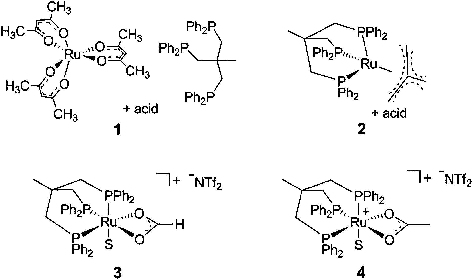 | ||
| Scheme 2 Catalyst precursors 1, 2 and 4 (S = free coordination site or solvent) for the CO2 hydrogenation to methanol and the structure of the catalytically active intermediate 3 (S = solvent). | ||
In the present report we disclose for the first time the hydrogenation of CO2to methanol using a single molecularly-defined homogeneous catalyst without the need for an alcohol additive (Scheme 1, lower pathway). This fundamental step forward was derived from comprehensive mechanistic investigations concerning the catalyst system 2 which led to the identification of the cationic formate complex [(Triphos)Ru(η2-O2CH)(S)]+ (S = solvent) 3 as a catalytically active intermediate in solution (Scheme 2). Based on this, the analogous cationic acetate complex 4 was developed as a pre-catalyst (Scheme 2). These molecular catalysts allow the homogeneously catalysed formation of methanol using CO2 and H2 as the sole feedstock with turnover frequencies in the same range as those reported for the active sites of the heterogeneous systems. We also demonstrate the possibility to separate and recycle these catalysts from the MeOH–water product mixture in a biphasic aqueous system using 2-methyl tetrahydrofuran (2-MTHF) as the catalyst phase.
Results and discussion
Basic reactivity and identification of the active species
Attempting to identify intermediates of the previously reported catalytic reaction sequence with catalyst 2,24,30 multinuclear NMR experiments were carried out to monitor the formation of organometallic species upon stepwise addition of the required components. Thus, a solution of the precursor [(Triphos)Ru(TMM)] (2) and HNTf2 (1 eq.) in d8-THF was pressurised with CO2 (20 bar at r.t.) and H2 (60 bar at r.t.), stirred for 1 h at 140 °C, and then transferred to a NMR tube for analysis. Unexpectedly, a sharp signal at 3.27 ppm in the 1H-NMR spectrum indicated the catalytic formation of MeOH in the absence of any alcohol additive with a TON (turnover number = mmol MeOH per mmol catalyst) of 35. Thus, one of the species formed under these conditions must have been able to serve as a catalyst for the hydrogenation of CO2 to methanol. The 31P{1H}-NMR spectrum of the clear, yellow solution obtained under these conditions is depicted in Fig. 1, the corresponding 1H, 13C and 2D-correlation spectra are shown in the ESI.† | ||
| Fig. 1 31P{1H}-NMR spectra (top: at r.t., bottom: at −40 °C) of the reaction solution after CO2 hydrogenation to methanol (20 bar CO2 + 60 bar H2, 140 °C, 1 h) with catalyst 2 (50 μmol) and HNTf2 (1 eq.) in d8-THF (2 mL). 5 = [(Triphos)RuH(CO)2]+, 6 = [Ru2(μ-H)2(Triphos)2], 7 = [Ru2(Cl)3(Triphos)2]+, 3a = [(Triphos)Ru(η2-O2CH)(THF)]+. | ||
Formation of the cationic carbonyl complex [(Triphos)RuH(CO)2]+ (5) was inferred from the characteristic set of a doublet (18.6 ppm, J = 28.7 Hz) and triplet (6.3 ppm, J = 28.7 Hz) in the 31P{1H}-NMR spectrum.31 Correlation with the hydride signal at δ = −6.7 ppm in the [1H,31P]-HMBC-NMR spectrum and ESI-MS analysis further confirmed this assignment. The content in solution was about 4% according to the integral ratios in the 31P{1H}-NMR spectrum. The formation of complex 5 corroborates the assumption of cationic complexes as catalytically active species. The carbonyl ligands are most likely formed by decarbonylation of intermediates on the pathway to methanol.28,32,33 Supporting this hypothesis, 5 was synthesised in pure form by stirring complex 2 together with 1 equivalent of HNTf2 in ethyl formate and 60 bar H2 in the absence of CO2 for 24 hours at 140 °C. Testing the isolated complex 5 for its catalytic activity in CO2 hydrogenation in the absence of alcohol (standard conditions: V(THF) = 2.08 mL, c(Ru) = 12 mmol L−1, 1 eq. of HNTf2, p(CO2) = 20 bar at r.t., p(H2) = 60 bar at r.t., T = 140 °C, t = 24 h) only gave a TON of 4, identifying the formation of 5 as a possible deactivation pathway.
The sharp singlet at 43.3 ppm in the 31P{1H}-NMR spectrum was correlated with a broad hydride signal at −8.7 ppm in the 1H-NMR spectrum by [1H,31P]-HMBC-NMR. Comparison with the literature data and analysis of the mixture by ESI-MS allowed unambiguous assignment of the dimeric complex [Ru2(μ-H)2(Triphos)2] (6), which formed in about 2%.29 Using isolated 6 in the CO2 hydrogenation reaction under standard conditions resulted in no formation of methanol, revealing the formation of 6 as a second major deactivation pathway.
The small sharp singlet at 36.7 ppm in the 31P{1H}-NMR spectrum was assigned to [Ru2(Cl)3(Triphos)2]+ (7) by comparison with the literature data and analysis of the mixture by ESI-MS (6% according to the integral ratios in the 31P{1H}-NMR spectrum).34 A CO2 hydrogenation reaction under standard conditions using the [(Triphos)Ru(TMM)] (2) precursor but with the addition of 1-butyl-3-methylimidazolium chloride (3 eq.) only gave a TON of 1 after 24 hours. The 31P{1H}-NMR spectrum of the solution showed the formation of 7, 5 and [(Triphos)RuH(CO)Cl] (18) indicating that Ru–Triphos complexes bearing chloro ligands are generally inactive in this transformation.35
The main species accounting for over 85% of the total signal intensity in the 31P{1H}-NMR spectrum gave rise to a broad singlet at 44.2 ppm, indicating fluxional behaviour at room temperature. Low-temperature NMR at 233 K resulted in the splitting of this signal into a doublet (46.3 ppm, 2P, J = 42.5 Hz) and a triplet (43.9 ppm, 1P, J = 42.5 Hz). A [1H,31P]-HMBC-NMR experiment revealed coupling of these signals to a proton signal at 8.7 ppm (bs), which is well in the range of ruthenium coordinated formate.36–38 A [1H, 13C]-HMBC-NMR experiment showed the coupling of the proton signal at 8.7 ppm to a singlet at 178.8 ppm in the 13C-NMR, further corroborating the formation of a formate-complex.23,39,40 No hydride signals corresponding to this species were detected in the respective correlation NMR spectra.
The same formate complex was generated independently by adding one equivalent of HNTf2 to complex 2 in d8-THF, followed by the addition of one equivalent of HCO2H at room temperature. NMR analysis of the crude reaction mixture at room temperature and 233 K showed an identical set of signals in the 31P{1H}-NMR spectrum in about 80% of the total intensity together with a second, yet unidentified phosphor containing species (singlet at 59 ppm, ca. 20% of total intensity), as well as in the 1H-NMR spectra (see ESI†). FT-IR analysis of this solution at room temperature showed a νCO stretching mode at 1543 cm−1, a typical value for η2-coordinated formate.37–40 Based on these data and on the basis of literature precedence,37 we assigned the structure of this complex as [(Triphos)Ru(η2-O2CH)(THF)]+ (3a), where the weakly bound solvent molecule THF accounts for the fluxionality at room temperature (Scheme 3).
 | ||
| Scheme 3 Formation of the catalytically active formate complex 3a from catalyst precursor 2 in the presence of 1 eq. HNTf2 and H2/CO2 under reaction conditions (upper pathway) and by addition of 1 eq. HNTf2 and 1 eq. HCO2H in THF. | ||
This interpretation is supported by the formation of a non-fluxional formate complex upon addition of 0.1 mL acetonitrile to the freshly prepared solution of 3a in 0.5 mL THF at room temperature (d, 42.8 ppm, 2P; t, 29.6 ppm, 1P, J = 42.2 Hz; see ESI† for details). FT-IR analysis of this solution at room temperature again showed a νCO stretching mode at 1544 cm−1, consistent with the structure [(Triphos)Ru(η2-O2CH)(MeCN)]+ (3b). Interestingly, the signals of 3b decreased over a period of 5 hours at room temperature at the expense of new doublet (47.6 ppm, 2P, J = 20.6 Hz) and triplet (5.5 ppm, 1P, J = 20.6 Hz) signals. In parallel, the formate signal at 8.7 ppm disappeared with concomitant formation of an upfield hydride signal (dt, −5.5 ppm, J = 105.0 Hz, J = 19.3 Hz) in the 1H-NMR spectrum. These NMR-data are consistent with the decarboxylation of 3b to give the literature reported complex [(Triphos)Ru(H)(MeCN)2]+ (8) (Scheme 4).41 Consequently, the formation of the formate complex 3 from 2 in the presence of HNTf2 under CO2 and hydrogen pressure is most plausibly explained via reversible CO2-insertion into the analogous solvent-coordinated cationic Ru–hydride complex as an intermediate.
 | ||
| Scheme 4 Formation of the acetonitrile formate complex 3b from 3a by addition of MeCN to a solution of 3a in THF and decarboxylation of 3b to the hydride complex 8 at room temperature. | ||
Ruthenium–formate complexes are well known as intermediates in the CO2 hydrogenation to formic acid.42–44 In order to probe whether the formate complex 3 is a kinetically competent intermediate in the hydrogenation of CO2 to methanol, a solution of 3a was prepared from 2/HNTf2 (1![[thin space (1/6-em)]](https://www.rsc.org/images/entities/char_2009.gif) :1) and HCO2H in d8-THF, pressurised with only 60 bar H2, and heated to 140 °C in an external oil bath in a high-pressure NMR tube for 40 minutes (Scheme 5). Indeed, this led to nearly complete conversion (ca. 97%) of the coordinated formate to methanol based on 1H-NMR analysis (see ESI†). In the corresponding 31P-NMR spectra the formation of [Ru2(μ-H)2(Triphos)2] (6) in around 44% yield was observed. Furthermore, in situ high pressure NMR studies using complex 2 directly under turnover conditions (2/HNTf2 (1:1), d8-THF, T = 80 °C, p(H2) = 60 bar, p(CO2) = 20 bar) revealed that complex 3a was formed immediately after pressurisation and remained the major detectable phosphorus containing species present in solution throughout the reaction. No hydride signals that could be related to an active species were observed in the 1H-NMR spectra (see ESI†). These data indicate that the presumed cationic hydride intermediate is too short-lived to be observed on the NMR-time-scale,37 but is converted to the observable formate complex [(Triphos)Ru(η2-O2CH)(THF)]+3a as the resting state by rapid and reversible CO2 insertion into the metal–hydride bond under turnover conditions.38,42–44
:1) and HCO2H in d8-THF, pressurised with only 60 bar H2, and heated to 140 °C in an external oil bath in a high-pressure NMR tube for 40 minutes (Scheme 5). Indeed, this led to nearly complete conversion (ca. 97%) of the coordinated formate to methanol based on 1H-NMR analysis (see ESI†). In the corresponding 31P-NMR spectra the formation of [Ru2(μ-H)2(Triphos)2] (6) in around 44% yield was observed. Furthermore, in situ high pressure NMR studies using complex 2 directly under turnover conditions (2/HNTf2 (1:1), d8-THF, T = 80 °C, p(H2) = 60 bar, p(CO2) = 20 bar) revealed that complex 3a was formed immediately after pressurisation and remained the major detectable phosphorus containing species present in solution throughout the reaction. No hydride signals that could be related to an active species were observed in the 1H-NMR spectra (see ESI†). These data indicate that the presumed cationic hydride intermediate is too short-lived to be observed on the NMR-time-scale,37 but is converted to the observable formate complex [(Triphos)Ru(η2-O2CH)(THF)]+3a as the resting state by rapid and reversible CO2 insertion into the metal–hydride bond under turnover conditions.38,42–44
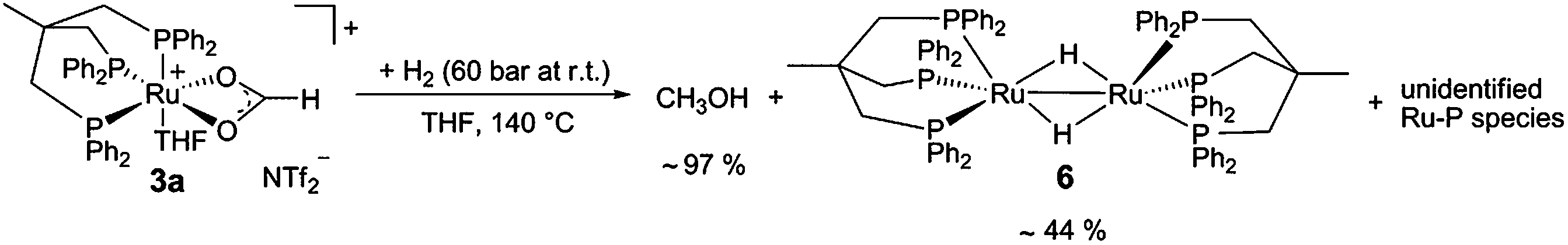 | ||
| Scheme 5 Methanol is formed with high yield by hydrogenation of complex 3a. | ||
Identification of the formate complex 3 as the active intermediate suggests that the major role of the acid additive in the catalytic system 2/HNTf2 is the generation of cationic species as the active site upon reductive removal of the TMM-ligand. In order to probe this assumption, we decided to start from an isolated cationic complex precursor. After numerous unsuccessful attempts to isolate complex 3 in a stable form as a solid, we turned our efforts towards the analogous cationic acetate complex. Stirring [(Triphos)Ru(η2-OAc)Cl] (9)45 together with one equivalent of AgNTf2 for 3 h at 60 °C in THF led to the precipitation of AgCl. The 31P{1H}-NMR spectrum showed the selective formation of only one sharp singlet at 44.0 ppm, indicating the formation of a symmetrical complex species. After filtration of the yellow solution over silica and removal of the solvent in vacuo a yellow powder was obtained. Characterisation of the material by 1H-, 13C- and 19F-NMR, FT-IR and ESI-HRMS revealed the presence of the cationic [(Triphos)Ru(η2-OAc)]+ fragment (see ESI†). Crystallisation from dichloromethane layered with pentane gave yellow single crystals of complex 4a where the open coordination site was saturated with H2O from adventitious traces of water (Fig. 2). Thus, the acetate complex in solution can be formulated as [(Triphos)Ru(η2-OAc)(S)][NTf2] (4) with S being a free coordination site or weakly bound solvent molecule.46 The formation of dimeric or trimeric species [(Triphos)Ru(μ-OAc)]x[NTf2]x could be excluded by using two structurally different Triphos derivatives and stirring an equimolar (12.5 μmol) mixture of [(Triphos)Ru(η2-OAc)Cl] (9) and [(Triphos-anisyl)Ru(η2-OAc)Cl] (10) (Triphos-anisyl = 1,1,1-tris{bis(4-methoxyphenyl)phosphinemethyl}ethan) together with AgNTf2 (30 μmol) in toluene (1.5 mL) at 60 °C for 5 hours. The toluene was removed in vacuo, the residue dissolved in d2-DCM (0.5 mL), and the mixture analysed by NMR. The 31P{1H}-NMR spectrum at room temperature showed two singlets at 43.5 and 45.3 ppm in a ratio of nearly 1:1 related to [(Triphos)Ru(η2-OAc)(S)]NTf2 (4) and [(Triphos-anisyl)Ru(η2-OAc)(S)]NTf2 (11), respectively. The absence of further signals due to mixed complexes (e.g. [Ru2(Triphos)(Triphos-anisyl)(μ-OAc)2][NTf2]2) supports the monomeric structure of 4 in solution.47
 | ||
| Fig. 2 Molecular structure of the cation 4a (S = H2O) in the solid state as derived from single crystal X-ray diffraction (hydrogen atoms are omitted for clarity). Some selected bond lengths (Å): Ru–P1 = 2.245(9); Ru–P2 = 2.255(3); Ru–P3 = 2.253(0); Ru–O1 = 2.171(2); Ru–O2 = 2.208(6); Ru–O3 = 2.204(7). | ||
The reactivity of the acetate complex 4 under CO2 (20 bar at r.t.) and H2 (60 bar at r.t.) pressure was investigated in a high pressure NMR experiment (see ESI†). After 1.5 hours at 80 °C and 1 hour at 140 °C, ca. 60% (31P{1H}-NMR) of 4 was converted to the formate complex 3a and ethanol from acetate hydrogenation was detected by 1H-NMR in the reaction mixture. Methanol was indeed observed in the solution with a TON of 5, confirming that the cationic complex 4 was operating as a molecularly defined direct precursor for the catalytic cycle for CO2 hydrogenation without the need of any acid additive.
Mechanistic pathways on the basis of DFT calculations
In summary, the experimental results described above clearly demonstrate that the Ru–Triphos framework is able to act as a molecular single-site catalyst for the hydrogenation of CO2 to methanol. All observations are in accordance with a stepwise reduction of CO2 to methanol via the formate anion in the coordination sphere of a homogeneous cationic organometallic complex. Complex 3, which is accessible from different precursors in the presence or absence of acid co-catalysts, represents the resting state under turnover conditions. Consequently, spectroscopic insight into the subsequent reduction steps cannot be obtained directly. We therefore used DFT calculations to explore possible reaction pathways for this multi-step transformation. Based on our previous investigations on the ruthenium–Triphos system and on recent work by other groups on the catalytic hydrogenation of CO2 or methanol reforming, a plausible basic catalytic cycle that reduces carbon dioxide stepwise through the formic acid and formaldehyde stage to methanol via the key intermediates I, V, IX, XVIII can be formulated as shown in Scheme 6.21,23,28,30,37,48–51 | ||
| Scheme 6 Basic catalytic cycle for the transformation of CO2 to methanol at the Ru–Triphos fragment via the formic acid and formaldehyde stage through the key intermediates I, V, IX, XVIII. P3Ru denotes the Triphos–Ru(II) fragment comprising additional ligands to fill the coordination sphere as discussed in the detailed analysis. | ||
Starting from a cationic ruthenium–hydride complex I, the migratory insertion of CO2 results in the formation of the spectroscopically observed ruthenium–formate species V. Reaction with one equivalent of hydrogen leads to reduction beyond the formic acid stage to give the respective ruthenium–hydroxymethanolate species IX, which is then transformed to the ruthenium–methanolate complex XVIIIvia intermediate formation of formaldehyde and consumption of a second equivalent of hydrogen.30,50,51 In the last step, hydrogenolysis of the Ru–OMe unit requires the third equivalent of H2 to liberate the product and closes the cycle by reforming the ruthenium–hydride complex I. A plausible structure for complex I as a starting point of the calculations is the cationic species [(Triphos)Ru(H)(H2)(THF)]+ that is, for example, most likely to be formed from complex 4 upon hydrogenative removal of the acetate ligand as the initiating step.28 The individual steps of the cycle shown in Scheme 6 were therefore analysed in detail from this starting point, whereby the reduction steps are composed of hydride migration/protonolysis events. For clarity, we constrain the discussion here to the most energetically favourable pathways and some particularly relevant alternatives and refer the reader to the ESI† for additional information.
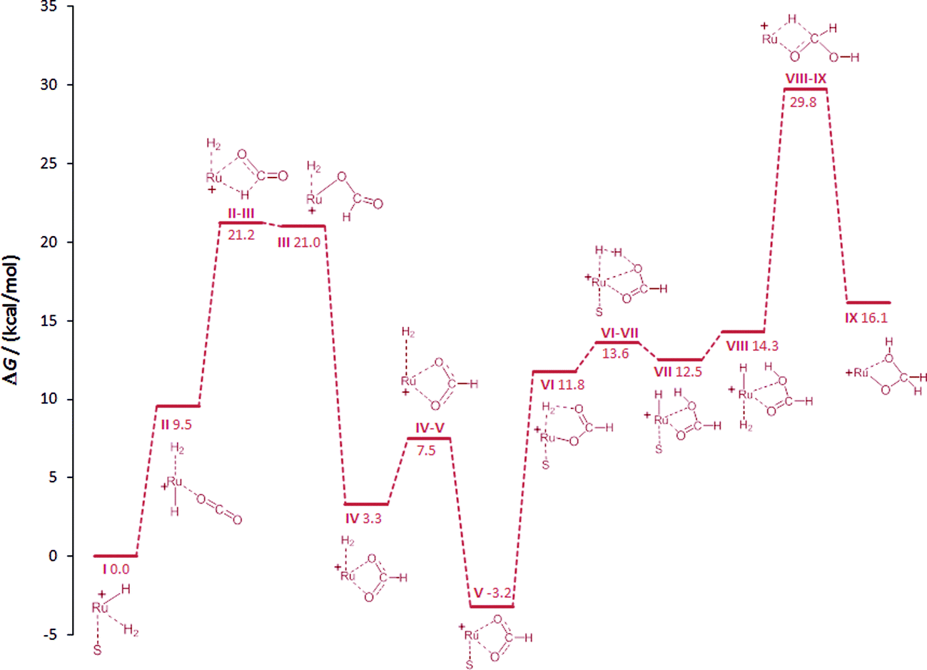 | ||
| Fig. 3 Initial steps of the DFT calculated reaction pathways for the hydrogenation of CO2 to methanol at the cationic Ru–Triphos centre, starting from complex I (S = THF) as the active species. The Triphos ligand is omitted for clarity. | ||
In the starting complex I either the THF molecule or the H2 molecule is replaced by CO2, generating complexes II and IIa, respectively. Both compounds are endergonic with respect to the reference point I by 8 and 10.2 kcal mol−1, respectively. The classical hydride centre in II can subsequently be transferred to the carbon atom of CO2, passing through transition state TSII–III. The barrier is appreciably low (11.7 kcal mol−1) placing the TSII–III at 21.2 kcal mol−1 on the hyper surface. Rotation of the formate species in III about the Ru–O and the O–C bonds generates complex IV (3.3 kcal mol−1), which is significantly more stable than III.43,48 The barrier for the dissociation of H2 from IV is very low (4.2 kcal mol−1) and the exchange of H2 in IV by solvent generates the stable ruthenium formate complex V (−3.2 kcal mol−1), which is also the experimentally observed resting state complex 3a.
In accordance with the work by Sakaki, the proton transfer to the carbonyl C![[double bond, length as m-dash]](https://www.rsc.org/images/entities/char_e001.gif) O bond in the six-membered transition state is also energetically favourable in the Ru–Triphos system.48 The change of coordination mode of the formate species in V from bidentate to monodentate with the subsequent coordination of H2 at the vacant coordination site forms VI. The coordinated H2 molecule is cleaved heterolytically viaTSVI–VII with a very small barrier of 1.7 kcal mol−1 to VII (12.5 kcal mol−1). At this point of the cycle, the generation of formic acid is complete and the Ru–H unit is regenerated for further reduction.
O bond in the six-membered transition state is also energetically favourable in the Ru–Triphos system.48 The change of coordination mode of the formate species in V from bidentate to monodentate with the subsequent coordination of H2 at the vacant coordination site forms VI. The coordinated H2 molecule is cleaved heterolytically viaTSVI–VII with a very small barrier of 1.7 kcal mol−1 to VII (12.5 kcal mol−1). At this point of the cycle, the generation of formic acid is complete and the Ru–H unit is regenerated for further reduction.
In contrast to the hydrogenation of CO2 to formic acid, far less is known about the reduction beyond the formate stage. Only most recently, ruthenium and iridium catalysts have been reported to facilitate this reaction step via unprecedented catalytic pathways.30,50,52,53 In the Ru–Triphos system, hydride transfer to the coordinated formic acid was found to be energetically accessible only after the solvent in VII is replaced by H2, generating complex VIII. The exchange of solvent by H2 is almost thermoneutral placing VIII at an energy of 14.3 kcal mol−1. The hydride transfer in VIII to the carbon atom of formic acid has a barrier of 15.5 kcal mol−1, placing TSVIII–IX at 29.8 kcal mol−1 on the hyper surface. This energetically feasible reaction step forms the ruthenium–hydroxymethanolate species (IX) which is the crucial intermediate for the unique performance of the Ru–Triphos system in the hydrogenation of CO2 beyond the formic acid stage. Three other energetically less favoured reaction pathways for the formation of hydroxymethanolate from CO2, including outer sphere attack of CO2, were calculated and are shown in the ESI.† The next key step is the cleavage of the carbon–oxygen bond leading to formaldehyde on the path to methanol.
 | ||
| Fig. 4 Calculated reaction pathways generating formaldehyde complex XVvia medium-assisted proton transfer (acetate: gray; water: blue). The Triphos ligand is omitted for clarity, S = THF. | ||
In essence, the C–O bond cleavage can be achieved from the hydroxymethanolate intermediate IX through pathways involving medium-assisted proton transfer or intramolecular proton transfer within the coordination sphere of the Ru-centre. The lowest energy pathway (ca. 28 kcal mol−1) from the presently investigated alternatives is provided by external proton transfer using carboxylates as the proton shuttle. The intramolecular pathways result in significantly higher barriers (ca. 40 kcal mol−1), but still provide general viable alternatives that are also in line with the experimental results described below.
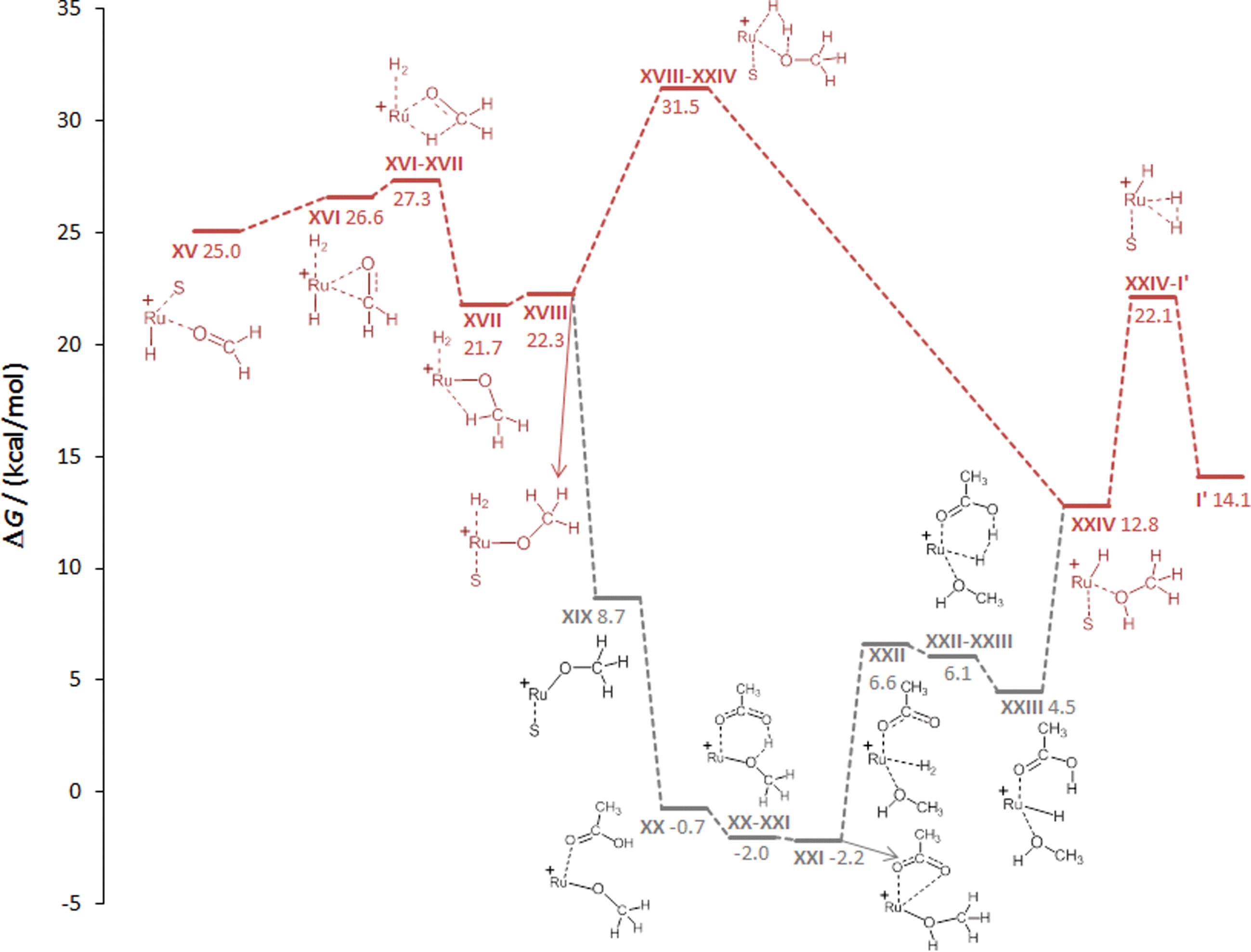 | ||
| Fig. 5 Calculated reaction pathways for the hydrogenation of formaldehyde generating methanol via intramolecular proton transfer (red) and carboxylate assisted proton transfer (acetic acid: grey). The Triphos ligand is omitted for clarity, S = THF. | ||
Similar to the protonolysis of the hydroxymethanolate complex, carboxylate-assisted proton transfer provides an alternative low energy pathway. Substitution of the hydrogen molecule in XVIII by acetic acid is energetically favourable to give XX and the subsequent protonation of the methanolate oxygen atom viaTSXX–XXI has no significant barrier and results in the acetate–methanol complex XXI (−2.2 kcal mol−1). Hydrogen addition (XXII) and carboxylate-assisted heterolytic cleavage of H2 to regenerate acetic acid (XXIII) can occur through a six-membered transition state, rendering this more facile than the direct heterolytic cleavage of the Ru–methanolate unit. The dissociation of acetic acid leads to XXIV at which point the two pathways merge again.
Overall, the results of the DFT calculations demonstrate the possibility of a stepwise reduction of CO2 to methanol in the coordination sphere of a single Ru–Triphos centre. The individual reduction steps occur by migratory transfer of classical Ru–hydride ligands, exhibiting low to moderate barriers in all cases. The protonolysis steps of the resulting Ru–O bonds can occur intramolecularly via heterolytic cleavage of coordinated H2 molecules. External proton transfer assisted by carboxylate groups present under turnover conditions may lower the corresponding barriers significantly.
Parameter variation and catalyst recycling in a biphasic system
After demonstrating the principle of the possibility for the catalytic hydrogenation of CO2 to methanol in the absence of an alcohol additive, the performance of the Ru–Triphos precursor systems 2 and 4 was evaluated further by the systematic variation of key reaction parameters and the results were corroborated for consistency with the mechanistic proposal (Table 1).| Entry | Cat | Acid (eq.) | T [°C] | p CO2/pH2b [bar/bar] | TONc |
|---|---|---|---|---|---|
| a Reaction conditions: 25 μmol [Ru], 2.08 mL THF, 24 h. b At room temperature. c TON = mmol MeOH per mmol catalyst. d 12.5 μmol [Ru]. e 6.3 μmol [Ru]. | |||||
| 1 | 2 | HNTf2 (1.0) | 140 | 20/60 | 228 |
| 2 | 2 | — | 140 | 20/60 | 8 |
| 3 | 4 | — | 140 | 20/60 | 165 |
| 4 | 4 | HNTf2 (0.5) | 140 | 20/60 | 156 |
| 5 | 2 | HNTf2 (1.5) | 140 | 20/60 | 196 |
| 6 | 2 | HNTf2 (2.0) | 140 | 20/60 | 181 |
| 7 | 2 | p-TsOH (1.0) | 140 | 20/60 | 135 |
| 8 | 2 | HNTf2 (1.0) | 120 | 20/60 | 169 |
| 9 | 2 | HNTf2 (1.0) | 100 | 20/60 | 67 |
| 10 | 2 | HNTf2 (1.0) | 80 | 20/60 | 24 |
| 11 | 2 | HNTf2 (1.0) | 140 | 10/30 | 78 |
| 12 | 2 | HNTf2 (1.0) | 140 | 30/90 | 367 |
| 13 | 2 | HNTf2 (1.0) | 140 | 20/80 | 301 |
| 14 | 2 | HNTf2 (1.0) | 140 | 20/100 | 348 |
| 15d | 2 | HNTf2 (1.0) | 140 | 20/60 | 335 |
| 16e | 2 | HNTf2 (1.0) | 140 | 20/60 | 442 |
| 17d | 12 | HNTf2 (1.0) | 140 | 20/60 | 256 |
Firstly, the catalyst systems 2 and 4 were compared under a standard set of reaction conditions (V(THF) = 2.08 mL, c(Ru) = 12 mmol L−1, p(CO2) = 20 bar at r.t., p(H2) = 60 bar at r.t., T = 140 °C, t = 24 h). Using 4 as the catalyst precursor for the CO2 hydrogenation in THF gave a TON of 165 in the absence of any additives (Table 1, entry 3). Using an additional 0.5 eq. HNTf2 did not show an increased TON (Table 1, entry 4). In contrast, precursor 2 showed only a very poor performance in the absence of the acid additive (Table 1, entry 2). However, a TON of 228 was obtained when conducting the CO2 hydrogenation reaction with catalyst 2 and 1 eq. of HNTf2 (Table 1, entry 1). The need for an acid additive in the case of precursor 2 is consistent with the formation of the cationic species [(Triphos)Ru(H)(H2)(S)]+, which is the catalytically active species I used as the starting point in the calculated catalytic cycle.
The lower TON obtained when using the acetate complex 4 instead of 2/HNTf2 (1:1) under otherwise identical conditions can be explained by the less efficient initiation with 4 due to the more difficult hydrogenation of the acetate groups to form the common intermediate 3a (vide supra). This distinct reactivity is also reflected in the catalytic experiments for the hydrogenation of the corresponding free acids: using 2 together with 1 eq. HNTf2, 100 equivalents of formic acid could be fully converted to methanol at a hydrogen pressure of 60 bar (at r.t.) and a reaction temperature of 140 °C within 24 hours, whereas a reaction temperature of 180 °C was necessary for the full conversion of 100 equivalents acetic acid to ethanol (c(Ru) = 12.5 mmol L−1, 2.0 mL THF). The efficient hydrogenation of formic acid under these conditions is in accordance with the proposed catalytic cycle shown in Scheme 6. To complete the picture, the hydrogenation of 100 equivalents of paraformaldehyde was also assessed and a full conversion was indeed achieved with the same catalytic system (c(Ru) = 12.5 mmol L−1, 2.0 mL THF, 0.2 mL H2O, 60 bar H2 at r.t., 140 °C, 24 h). Again, the formation of formate complex 3a was observed in the 31P{1H}-NMR spectrum, indicating the full reversibility of the catalytic cycle.
The lack of activity with catalyst 2 in the absence of acid can be directly corroborated with the formation of the neutral complex [(Triphos)Ru(H)2CO] (12), which was observed as the almost exclusive species present in solution by 31P{1H}-NMR spectroscopy under these conditions (see ESI†).28 The protonation of this complex with strong protic acids was shown by Zanobini et al. to lead to the formation of the complex [(Triphos)Ru(CO)(H)(H2)]+ (13), a cationic structure closely resembling the active hydride species I inferred above.56 Using the isolated complex 12 together with 1 equivalent of HNTf2 in THF indeed resulted in an active catalyst for the CO2 hydrogenation reaction yielding a TON of 256 after 24 h (Table 1, entry 17), which is about 76% of the TON obtained using the catalyst 2/HNTf2 under identical conditions (Table 1, entry 15). Again, formation of the formate intermediate 3a was observed when the solution was analysed by 31P{1H}-NMR (see ESI†).
Variation of the amount of HNTf2 added to complex 2 revealed a maximum observed TON at a 1:1 ratio (Table 1, entries 5 and 6) corresponding to the stoichiometric ratio required for the reductive removal of the TMM-ligand leading to I. Using 2 together with 1 eq. p-TsOH instead of HNTf2 gave a lower TON of 135 (Table 1, entry 7) under otherwise identical conditions. NMR-analysis of the reaction solution after 1 h reaction time showed the formation of the formate species 3a as the major component in solution in both cases (see ESI†). However, [(Triphos)Ru(p-TsO)2] (14) was also present in about 15% as indicated by a broad singlet at 38.7 ppm in the 31P{1H}-NMR spectrum measured at room temperature, which split up into a triplet (δ = 42.0 ppm, J = 47.5 Hz) and doublet (δ = 36.1 ppm, J = 47.5 Hz) when measured at 233 K in d8-THF. This assignment was supported by mass spectrometry (FAB) and the independent generation of 14 by addition of 2 equivalents of p-TsOH to 2 in THF at room temperature. Thus, the presence of even weakly-coordinating anions in the reaction mixture hampers the formation of the formate species 3a, explaining the preferred choice of HNTf2 as the acid additive.
After identifying the system 2/HNTf2 (1:1) as the most practical and effective catalyst precursor so far, the influence of some key reaction parameters on the TON after 24 hours reaction time was assessed. Lowering the catalyst concentration together with the acid concentration from 12 μmol mL−1 to 6 μmol mL−1 and further to 3 μmol mL−1 resulted in a significant increase in TON from 228 to 335 and 442, respectively (Table 1, entries 1, 15 and 16). Although final conclusions cannot be drawn before a detailed kinetic analysis, the formation of the dimeric complex 6 as part of the deactivation mechanism is in line with this trend. Decreasing the reaction temperature to 120 °C, 100 °C and 80 °C resulted in reduced TONs of 169, 67 and 24 (Table 1, entries 8–10), respectively. Variation of the total pressure while maintaining the stoichiometric ratio of p(CO2)/p(H2) = 1/3 from 40 bar to 80 bar and 120 bar resulted in an increase of the obtained TONs from 78 to 228 and 367 (Table 1, entries 11, 1 and 12), respectively. Using an excess of H2 (20 bar CO2 + 80 bar or 100 bar H2) resulted in largely increased TONs of 301 and 348 (Table 1, entries 13 and 14), respectively. In the latter case about 40% of the totally available carbon feedstock CO2 was converted to methanol, as calculated from the amount of MeOH formed (8.7 mmol) and the amount of CO2 initially charged (22.1 mmol, determined by weight).
A conversion/time profile of the CO2 hydrogenation to methanol in THF using 2/HNTf2 (1:1, 12.5 μmol; otherwise standard conditions) was mapped out by the termination of batch reactions after different reaction times (Fig. 6). The reaction started without any pronounced induction period, reaching a TON of 70 after just 1 hour. This corresponds to an initial turnover frequency (TOF) of 70 h−1 that is well in the range of the activity of the active sites in the state-of-the-art heterogeneous Cu/ZnO-based catalysts.18 Methanol formation continued smoothly, reaching a TON of 258 after 16 hours. At this point the pressure in the reactor vessel had dropped from an initial 120 bar to 72 bar due to the consumption of the reactive gases. Therefore, a reaction was conducted for 32 h where the reactor was re-pressurised to the initial pressure with p(CO2)/p(H2) = 1/3 after 16 hours leading to a TON of 478. Finally, a reaction was run for 48 hours with re-pressurisation to the initial pressure with p(CO2)/p(H2) = 1/3 after 16 hours and again after 32 hours, yielding a total TON of 603. These experiments clearly indicate the high stability of the active catalyst, resulting in a nearly linear increase of the TON under isobaric conditions. The absence of an induction period indicates that the presence of methanol is not enhancing the rate of catalysis under these conditions. This does not rule out the possibility that the reaction also partly proceeds via a cascade reaction involving methyl formate as an intermediate once methanol has been formed, as catalyst 2 is able to promote the hydrogenation of alkyl formates to methanol.24
 | ||
| Fig. 6 Conversion/time profile of the hydrogenation of CO2 to methanol using catalyst 2 (12.5 μmol catalyst 2; 12.5 μmol HNTf2, 20 bar CO2 + 60 bar H2 at r.t.; 140 °C reaction temperature; 2.08 mL THF), as obtained from batch experiments terminated at the given reaction times. In the case of the reaction terminated after 32 h the autoclave was re-pressurised to the initial pressure with p(CO2)/p(H2) = 1/3 after 16 h (▲). In the case of the reaction terminated after 48 h the autoclave was re-pressurised after 16 h and again after 32 h (●). | ||
As all of the previous results were consistent with the cationic Ru–Triphos formate complex 3 as the resting state in this process, we explored strategies for the recycling of the catalyst in its active form. Considering the various options for the isolation of the product MeOH from the homogeneous catalyst, distillation seemed an obvious possibility. However, the hydrogenation of CO2 yields a stoichiometric amount of water, which is the least volatile component in the THF–MeOH–water product mixture. Thus, it would accumulate upon stripping of the MeOH product, ultimately becoming the limiting factor even if the catalyst would be thermally stable for recycling. Multiphase catalysis offered an alternative strategy, where the separation is based on differences in solubility rather than volatility. For the current process, an aqueous biphasic system was envisaged, where the catalyst is retained and recycled in an organic phase, whereas the product is removed in an aqueous phase for downstream processing.57,58 Substitution of the solvent THF with 2-methyl tetrahydrofuran (2-MTHF) opened up the possibility for the realisation of such a biphasic reaction/separation system as 2-MTHF has a miscibility gap with water.27 All material streams can be recycled internally in such a process scheme, also providing the possibility for continuous-flow operation (Fig. 7).
 | ||
| Fig. 7 Aqueous biphasic system for recycling of the cationic Ru–Triphos catalyst in the organic 2-MTHF phase and removing the product MeOH in the aqueous phase for downstream processing. | ||
Assessing the partitioning of methanol in a 2-MTHF–water biphasic mixture showed that 80% of 0.2 mL MeOH can be isolated from 1.0 mL of 2-MTHF using 1.0 mL water in a single extraction step. Application of 2-MTHF as the solvent for the catalytic reaction under standard conditions (p(CO2) = 20 bar/p(H2) = 60 bar at r.t., T = 140 °C, V(solvent) = 2.08 mL) was also found to be possible without any problems for the catalyst 2 (25 μmol complex 2, 2/HNTf2 = 1:1), albeit with a somewhat lower TON of 186 after 24 h as compared to THF. To validate the combination of reaction and separation, a reaction with 2 (12.5 μmol complex 2, 2/HNTf2 = 1:1) in 2-MTHF (2.0 mL) was terminated after 16 hours, the reaction mixture extracted by the addition of 2.0 mL H2O, and the orange catalyst/2-MTHF phase was recycled to the autoclave after simple decantation. A small amount of fresh 2-MTHF (0.25 mL) was added to compensate for any loss of 2-MTHF with the product phase. The aqueous layers were analysed for MeOH content by quantitative 1H-NMR in d6-acetone using mesitylene as the standard, and only the concentration in the aqueous streams was used for the calculation of the apparent TON. As seen from Fig. 8, the catalyst system 2/HNTf2 could be recycled three times, resulting in a total TON of 769 after 4 cycles. The TON per cycle was reduced significantly especially between cycles three and four, but still nearly 50% of the initial productivity was retained in this non-optimised sequence.
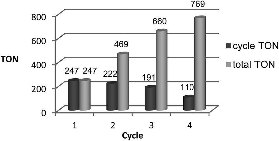 | ||
| Fig. 8 Recycling of the catalyst system 2 (12.5 μmol complex 2, 2/HNTf2 = 1:1) using 2-MTHF (2.0 mL) as the solvent and water (2.0 mL) as the extracting agent in an aqueous biphasic system. Each cycle was run for 16 h (20 bar CO2 + 60 bar H2 at r.t.; 140 °C reaction temperature). The TONs obtained per cycle are shown in dark grey, the total TONs summing up the cycles are shown in light grey. | ||
Conclusions
The results of this study demonstrate for the first time the hydrogenation of CO2 to methanol using a single organometallic catalyst in a homogenous solution without the need for an alcohol additive. The experimental and theoretical results are consistent with a mechanistic picture where this unprecedented transformation occurs at a cationic Triphos–Ru fragment as a molecularly-defined active site. The cationic formate complex [(Triphos)Ru(η2-O2CH)(S)]+ (3) (S = solvent) represents the resting state of the catalytic cycle under turnover conditions and can be obtained from various stable and readily available catalyst precursors. Through a series of hydride transfer and protonolysis steps, the CO2 reduction can pass through the formic acid and formaldehyde stages within the coordination sphere of a single ruthenium centre. The barriers for the proton transfer steps may be significantly lowered if assisted by the reaction medium. The active species shows remarkable stability, with decarbonylation and dimerisation as potential deactivation mechanisms. Recycling of the catalyst is possible in the aqueous biphasic system 2-MTHF–water, opening the possibility for continuous-flow operation.The Triphos–ruthenium system is the very first homogeneous catalyst to enable this transformation. The facial coordination of the Triphos ligand imposes a favorable geometrical arrangement for the hydride transfer to carboxylate units in general (see ESI† for a comparison of facial with meridional arrangement).28 Furthermore, the heterolytic cleavage of hydrogen offers low-energy pathways for the protonolysis of Ru–O units during the regeneration of the hydride ligand. Together with the high thermal stability of Triphos–ruthenium complexes, these features seem to play an important role in the reduction of CO2 beyond the formate stage with this catalyst. Further developments on the basis of the methodological approach of organometallic chemistry e.g. by systematic ligand variation based on the current mechanistic hypothesis are likely to produce even more active and stable systems. Already at this early stage of the development, turnover frequencies per Ru-centre are in the same range as for the active sites in traditional heterogeneous catalysts for methanol synthesis. The possibility to operate under multiphase conditions provides opportunities to overcome the limitations in productivity inherent to batch or repetitive batch operation. Therefore, we believe that the results of this study provide not only fundamental mechanistic insights into the activation and transformation of CO2 and H2 in organometallic chemistry, but also open promising targets for research at the interface of molecular and engineering sciences.
Acknowledgements
This work was supported in part by the Cluster of Excellence “Tailor-Made Fuels from Biomass”, which is funded by the Excellence Initiative by the German Federal and State Governments to promote science and research at German universities and in part by the project SusChemSys. The project “Sustainable Chemical Synthesis (SusChemSys)” is co-financed by the European Regional Development Fund (ERDF) and the state of North Rhine-Westphalia, Germany, under the Operational Programme “Regional Competitiveness and Employment” 2007–2013. Generous allocation of computer time by the Computation and Communication Centre of RWTH Aachen University is gratefully acknowledged.References
- M. Peters, B. Köhler, W. Kuckshinrichs, W. Leitner, P. Markewitz and T. E. Müller, ChemSusChem, 2011, 4, 1216–1240 CrossRef CAS PubMed.
- M. Cokoja, C. Bruckmeier, B. Rieger, W. A. Herrmann and F. E. Kühn, Angew. Chem., Int. Ed., 2011, 50, 8510–8537 CrossRef CAS PubMed.
- M. Aresta and A. Dibenedetto, Dalton Trans., 2007, 2975–2992 RSC.
- T. Sakakura, J. C. Choi and H. Yasuda, Chem. Rev., 2007, 107, 2365–2387 CrossRef CAS PubMed.
- A. Behr, Angew. Chem., Int. Ed., 1988, 27, 661–678 CrossRef.
- D. J. Darensbourg and R. A. Kudaroski, Adv. Organomet. Chem., 1983, 22, 129–168 CrossRef CAS.
- P. Braunstein, D. Matt and D. Nobel, Chem. Rev., 1988, 88, 747–764 CrossRef CAS.
- D. Walther, Coord. Chem. Rev., 1987, 79, 135–174 CrossRef CAS.
- W. Leitner, Coord. Chem. Rev., 1996, 153, 257–284 CrossRef CAS.
- G. Centi, E. A. Quadrelli and S. Perathoner, Energy Environ. Sci., 2013, 6, 1711–1731 CAS.
- R. Fornika and E. Dinjus, Carbon Dioxide as C1-Building Block, in Applied Homogeneous Catalysis with Organometallic Compounds, ed. B. Cornils and W.A. Herrmann, VCH, Weinheim, 1996, pp.1048–1071 Search PubMed.
- A. Goeppert, M. Czaun, G. K. S. Prakash and G. A. Olah, Energy Environ. Sci., 2012, 5, 7833–7853 CAS.
- F. Asinger, Methanol: Chemie und Energierohstoff, Springer-Verlag, Berlin, 1986 Search PubMed.
- A. Goeppert, G. K. S. Prakash and G. A. Olah, Beyond Oil and Gas: The Methanol Economy, WILEY-VCH, Weinheim, 2006 Search PubMed.
- M. Bertau, H. Offermanns, L. Plass, F. Schmidt and H.-J. Wernicke, Methanol: The Basic Chemical and Energy Feedstock of the Future, Springer, Berlin/Heidelberg, 2014 Search PubMed.
- W. Wang, S. P. Wang, X. B. Ma and J. L. Gong, Chem. Soc. Rev., 2011, 40, 3703–3727 RSC.
- http://www.carbonrecycling.is/, 2014.
- M. Behrens, F. Studt, I. Kasatkin, S. Kuhl, M. Havecker, F. Abild-Pedersen, S. Zander, F. Girgsdies, P. Kurr, B. L. Kniep, M. Tovar, R. W. Fischer, J. K. Norskov and R. Schlögl, Science, 2012, 336, 893–897 CrossRef CAS PubMed.
- K. Tominaga, Y. Sasaki, T. Watanabe and M. Saito, Bull. Chem. Soc. Jpn., 1995, 68, 2837–2842 CrossRef CAS.
- S. Chakraborty, J. Zhang, J. A. Krause and H. R. Guan, J. Am. Chem. Soc., 2010, 132, 8872–8873 CrossRef CAS PubMed.
- E. Balaraman, C. Gunanathan, J. Zhang, L. J. W. Shimon and D. Milstein, Nat. Chem., 2011, 3, 609–614 CrossRef CAS PubMed.
- E. Balaraman, Y. Ben-David and D. Milstein, Angew. Chem., Int. Ed., 2011, 50, 11702–11705 CrossRef CAS PubMed.
- C. A. Huff and M. S. Sanford, J. Am. Chem. Soc., 2011, 133, 18122–18125 CrossRef CAS PubMed.
- S. Wesselbaum, T. vom Stein, J. Klankermayer and W. Leitner, Angew. Chem., Int. Ed., 2012, 51, 7499–7502 CrossRef CAS PubMed.
- H. T. Teunissen and C. J. Elsevier, Chem. Commun., 1998, 1367–1368 RSC.
- T. vom Stein, T. Weigand, C. Merkens, J. Klankermayer and W. Leitner, ChemCatChem, 2013, 5, 439–441 CrossRef CAS.
- F. M. A. Geilen, B. Engendahl, A. Harwardt, W. Marquardt, J. Klankermayer and W. Leitner, Angew. Chem., Int. Ed., 2010, 49, 5510–5514 CrossRef CAS PubMed.
- F. M. Geilen, B. Engendahl, M. Hölscher, J. Klankermayer and W. Leitner, J. Am. Chem. Soc., 2011, 133, 14349–14358 CrossRef CAS PubMed.
- J. Coetzee, D. L. Dodds, J. Klankermayer, S. Brosinski, W. Leitner, A. M. Slawin and D. J. Cole-Hamilton, Chemistry, 2013, 19, 11039–11050 CrossRef CAS PubMed.
- M. Nielsen, E. Alberico, W. Baumann, H. J. Drexler, H. Junge, S. Gladiali and M. Beller, Nature, 2013, 495, 85–89 CrossRef CAS PubMed.
- S. I. Hommeltoft and M. C. Baird, Organometallics, 1986, 5, 190–195 CrossRef CAS.
- K. Tominaga and Y. Sasaki, J. Mol. Catal. A: Chem., 2004, 220, 159–165 CrossRef CAS PubMed.
- N. Sieffert, R. Reocreux, P. Lorusso, D. J. Cole-Hamilton and M. Buhl, Chem.–Eur. J., 2014, 20, 4141–4155 CrossRef CAS PubMed.
- B. D. Yeomans, D. G. Humphrey and G. A. Heath, J. Chem. Soc., Dalton Trans., 1997, 4153–4166 RSC.
- K. M. Sung, S. Huh and M. J. Jun, Polyhedron, 1999, 18, 469–479 CrossRef CAS.
- O. R. Allen, S. J. Dalgarno, L. D. Field, P. Jensen and A. C. Willis, Organometallics, 2009, 28, 2385–2390 CrossRef CAS.
- I. Mellone, M. Peruzzini, L. Rosi, D. Mellmann, H. Junge, M. Beller and L. Gonsalvi, Dalton Trans., 2013, 42, 2495–2501 RSC.
- M. K. Whittlesey, R. N. Perutz and M. H. Moore, Organometallics, 1996, 15, 5166–5169 CrossRef CAS.
- I. S. Kolomnikov, A. I. Gusev, G. G. Aleksandrov, T. S. Lobeeva, Y. T. Struchkov and M. E. Volpin, J. Organomet. Chem., 1973, 59, 349–351 CrossRef CAS.
- M. G. Bradley, D. A. Roberts and G. L. Geoffroy, J. Am. Chem. Soc., 1981, 103, 379–384 CrossRef CAS.
- C. Bianchini, A. Meli, S. Moneti and F. Vizza, Organometallics, 1998, 17, 2636–2645 CrossRef CAS.
- A. D. Getty, C.-C. Tai, J. C. Linehan, P. G. Jessop, M. M. Olmstead and A. L. Rheingold, Organometallics, 2009, 28, 5466–5477 CrossRef CAS.
- A. Urakawa, F. Jutz, G. Laurenczy and A. Baiker, Chem.–Eur. J., 2007, 13, 3886–3899 CrossRef CAS PubMed.
- P. G. Jessop, F. Joo and C.-C. Tai, Coord. Chem. Rev., 2004, 248, 2425–2442 CrossRef CAS PubMed.
- A. B. Chaplin and P. J. Dyson, Inorg. Chem., 2008, 47, 381–390 CrossRef CAS PubMed.
- M. Hirano, R. Fujimoto, K. Hatagami, N. Komine and S. Komiya, ChemCatChem, 2013, 5, 1101–1115 CrossRef CAS.
- J. M. Brown, I. Gridnev and J. Klankermayer, Amplification of Chirality, 2008, vol. 284, pp. 35–65 Search PubMed.
- Y. Musashi and S. Sakaki, J. Am. Chem. Soc., 2000, 122, 3867–3877 CrossRef CAS.
- C. Fellay, N. Yan, P. J. Dyson and G. Laurenczy, Chem.–Eur. J., 2009, 15, 3752–3760 CrossRef CAS PubMed.
- L. E. Heim, N. E. Schlörer, J.-H. Choi and M. H. G. Prechtl, Nat. Commun., 2014, 5 DOI:10.1038/ncomms4621.
- X. Yang, ACS Catal., 2014, 4, 1129–1133 CrossRef CAS.
- A. J. M. Miller, D. M. Heinekey, J. M. Mayer and K. I. Goldberg, Angew. Chem., Int. Ed., 2013, 52, 3981–3984 CrossRef CAS PubMed.
- S. Savourey, G. Lefevre, J. C. Berthet, P. Thuery, C. Genre and T. Cantat, Angew. Chem., Int. Ed, 2014, 53, 10466–10470 CrossRef CAS PubMed.
- F. Hutschka, A. Dedieu and W. Leitner, Angew. Chem., Int. Ed., 1995, 34, 1742–1745 CrossRef CAS.
- F. Hutschka, A. Dedieu, M. Eichberger, R. Fornika and W. Leitner, J. Am. Chem. Soc., 1997, 119, 4432–4443 CrossRef CAS.
- V. I. Bakhmutov, E. V. Bakhmutova, N. V. Belkova, C. Bianchini, L. M. Epstein, D. Masi, M. Peruzzini, E. S. Shubina, E. V. Vorontsov and F. Zanobini, Can. J. Chem., 2001, 79, 479–489 CrossRef CAS.
- G. Verspui, G. Elbertse, F. A. Sheldon, M. A. P. J. Hacking and R. A. Sheldon, Chem. Commun., 2000, 1363–1364 RSC.
- K. Burgemeister, G. Francio, V. H. Gego, L. Greiner, H. Hugl and W. Leitner, Chem.–Eur. J., 2007, 13, 2798–2804 CrossRef CAS PubMed.
Footnote |
| † Electronic supplementary information (ESI) available: Experimental procedures, analytical data. CCDC 1014053. For ESI and crystallographic data in CIF or other electronic format see DOI: 10.1039/c4sc02087a |
| This journal is © The Royal Society of Chemistry 2015 |